


Bobcat 225G
Table of contents
 Loading...
January 1997 Form: OM-175 104B
Gasoline Engine
Effective With Serial No. KG191348
OWNER’S
MANUAL
Welding
Mode
CC/AC 50
CC/DC
CV/DC
cover_om 4/95 – Ref. ST-801 188-A PRINTED IN USA
Bobcat 225G
(Kohler-Powered)
CC/CV AC/DC Welding Generator For SMAW, FCAW, GMAW, GTAW Welding
Weld
Output
Range
– 225 A
50 – 210 A
17 – 28 V
Rated
Welding
Output
225 A, 25 V
100% Duty
Cycle
210 A, 25 V
100% Duty
Cycle
200 A, 20 V
100% Duty
Cycle
Maximum
Open-Circu
it Voltage
,
,
,
Auxiliary Power
Rating
80
72
33
Single-Phase,
8 kVA/kW
120/240 V AC, 60 Hz
1997 MILLER Electric Mfg. Co.
, 70/35 A,
Fuel Capacity Engine
8.5 gal (32 L) T
ank
Kohler CH18
Air-Cooled, T
Four-Cycle, 18 HP
Gasoline Engine
wo-Cylinder,

TABLE OF CONTENTS
SECTION 1 – SAFETY PRECAUTIONS FOR ARC WELDING 1.
1-1. Symbol Usage 1.
1-2. Arc Welding Hazards 1.
1-3. Engine Hazards 2.
1-4. Additional Installation, Operation, And Maintenance Hazards 3.
1-5. Principal Safety Standards 3.
1-6. EMF Information 3.
SECTION 2 – DEFINITIONS 4.
2-1. Symbol Definitions 4.
SECTION 3 – INSTALLATION 5.
3-1. Installing Welding Generator 5.
3-2. Dimensions, Weights, And Operating Angles 5.
3-3. Fuel Consumption 6.
3-4. Engine Prestart Checks 6.
3-5. Connecting The Battery 7.
3-6. Weld Output Terminals And Selecting Cable Sizes 7.
SECTION
4 – OPERA
4-1. Front Panel Controls 8.
4-2. Duty Cycle 9.
. . . . . . . . . . . . . . . . . . . . . . . . . . . . . . . . . . . . . . . . . . . . . . . . . . . . . . . . . . . . . . . .
. . . . . . . . . . . . . . . . . . . . . . . . . . . . . . . . . . . . . . . . . . . . . . . . . . . . . . . . . . .
. . . . . . . . . . . . . . . . . . . . . . . . . . . . . . . . . . . . . . . . . . . . . . . . . . . . . . . . . . . . . . .
. . . . . . . . . . . . . . . . . . . . . . . . . . . . . . . . . . . . . . . . . . . . . . . . . . . . . .
. . . . . . . . . . . . . . . . . . . . . . . . . . . . . . . . . . . . . . . . . . . . . . . . . . . . . . . . . . . . . .
. . . . . . . . . . . . . . . . . . . . . . . . . . . . . . . . . . . . . . . . . . . . . . . . . . . . . . . . . . . . . .
. . . . . . . . . . . . . . . . . . . . . . . . . . . . . . . . . . . . . . . . . . . . . . . . . . . . . . . . . . . . .
. . . . . . . . . . . . . . . . . . . . . . . . . . . . . . . . . . . . . . . . . . . . . . . . . . . . . . . . . . . .
. . . . . . . . . . . . . . . . . . . . . . . . . . . . . . . . . . . . . . . . . . . . . . . . . . . .
. . . . . . . . . . . . . . . . . . . . . . . . . . . . . . . . . . . . . .
. . . . . . . . . . . . . . . . . . . . . . . . . . . . . . . . . . . . . . . . . . . . . . . . . . . . . . . . . . . . .
. . . . . . . . . . . . . . . . . . . . . . . . . . . . . . . . . . . . . . . . . . . . . . . . . . . . . . . .
. . . . . . . . . . . . . . . . . . . . . . . . . . . . . . . . . . . . . . . . . . . . . . . . . . . . . . . .
. . . . . . . . . . . . . . . . . . . . . . . . . . . . . . . . .
TING WELDING GENERATOR 8.
. . . . . . . . . . . . . . . . . . . . . . . . . . . . . . . . . . . . . . . . . . . . . . . . . . . . . . . . . . .
. . . . . . . . . . . . . . . . . . . . . . . . . . . . . . . . . . . . . . . . . . . . . . . . . . . . . . . . . . . . . . . . . . . .
. . . . . . . . . . . . . . . . . . . . . . . . . . . . . . . . . . . . . . . .
. . . . . . . . . . . . . . . . . . . . . . . . . . . . . . . .
. . . . . . . . . . . . . . . . . . . . . . . .
SECTION
SECTION 6 – MAINTENANCE AND TROUBLESHOOTING 13.
SECTION 7 – ELECTRICAL DIAGRAM 20.
SECTION 8 – PARTS LIST 21.
5 – OPERA
5-1. Standard Receptacles 10.
5-2. Optional Auxiliary Power Receptacles 11.
5-3. Wiring Optional 240 Volt Plug 12.
6-1. Routine Maintenance 13.
6-2. Maintenance Label 14.
6-3. Servicing Air Cleaner 14.
6-4. Changing Engine Oil, Oil Filter, And Fuel Filter 15.
6-5. Adjusting Engine Speed 16.
6-6. Overload Protection 17.
6-7. Inspecting And Cleaning Optional Spark Arrestor 17.
6-8. Troubleshooting 18
TING AUXILIAR
. . . . . . . . . . . . . . . . . . . . . . . . . . . . . . . . . . . . . . . . . . . . . . . . . . . . . . . . . . . . . . . .
. . . . . . . . . . . . . . . . . . . . . . . . . . . . . . . . . . . . . . . . . . . . . . . . . . . . . . . . . . . . . . .
Y EQUIPMENT
. . . . . . . . . . . . . . . . . . . . . . . . . . . . . . . . . . . . . . . . . . . . . . . . . . . . . . . . . .
. . . . . . . . . . . . . . . . . . . . . . . . . . . . . . . . . . . . . . . . . . . . . . . . . . .
. . . . . . . . . . . . . . . . . . . . . . . . . . . . . . . . . . . . . . . . . . . . . . . . . . . . . . . . . .
. . . . . . . . . . . . . . . . . . . . . . . . . . . . . . . . . . . . . . . . . . . . . . . . . . . . . . . . . . . .
. . . . . . . . . . . . . . . . . . . . . . . . . . . . . . . . . . . . . . . . . . . . . . . . . . . . . . . . . .
. . . . . . . . . . . . . . . . . . . . . . . . . . . . . . . . . . . . . . . . . . . . . . . . . . . . . . . .
. . . . . . . . . . . . . . . . . . . . . . . . . . . . . . . . . . . . . . . . . . . . . . . . . . . . . . . . . . . .
. . . . . . . . . . . . . . . . . . . . . . . . . . . . . . . . . . . . . . . . . . . . . . . . . . . .
. . . . . . . . . . . . . . . . . . . . . . . . . . . . . . . . . . . . . . .
. . . . . . . . . . . . . . . . . . . . . . . . . . . . . . . . . . . . . . . . . . . .
. . . . . . . . . . . . . . . . . . . . . . . . . . . . . . . . . .
. . . . . . . . . . . . . . . . . . . . . . . . . . . . . . . . . . . .
. . . . . . . . . . . . . . . . . . . . . . . . . . . . . . . . . .
10.
OM-175 104B – 1/97
SECTION 1 – SAFETY PRECAUTIONS FOR ARC WELDING
safety_rom1 4/95
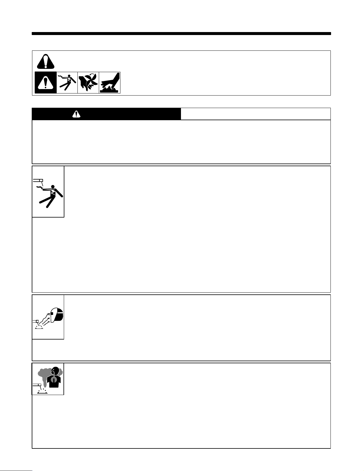
1-1. Symbol Usage
Y
Means Warning! Watch Out! There are possible hazards with this
procedure!
The possible hazards are shown in the adjoining symbols.
This group of symbols means Warning! Watch Out! possible ELECTRIC SHOCK, MOVING
and HOT PARTS hazards. Consult symbols and related instructions below for necessary
PARTS,
actions
to avoid the hazards.
1-2. Arc Welding Hazards
WARNING
The symbols shown below are used throughout this manual to call attention to and identify possible hazards.
When you see the symbol, watch out, and follow the related instructions to avoid the hazard. The safety
information given below is only a summary of the more complete safety information found in the Safety
Standards listed in Section 1-5. Read and follow all Safety Standards.
Only qualified persons should install, operate, maintain, and repair this unit.
During operation, keep everybody, especially children, away.
Marks a special safety message.
.
Means NOTE; not safety related.
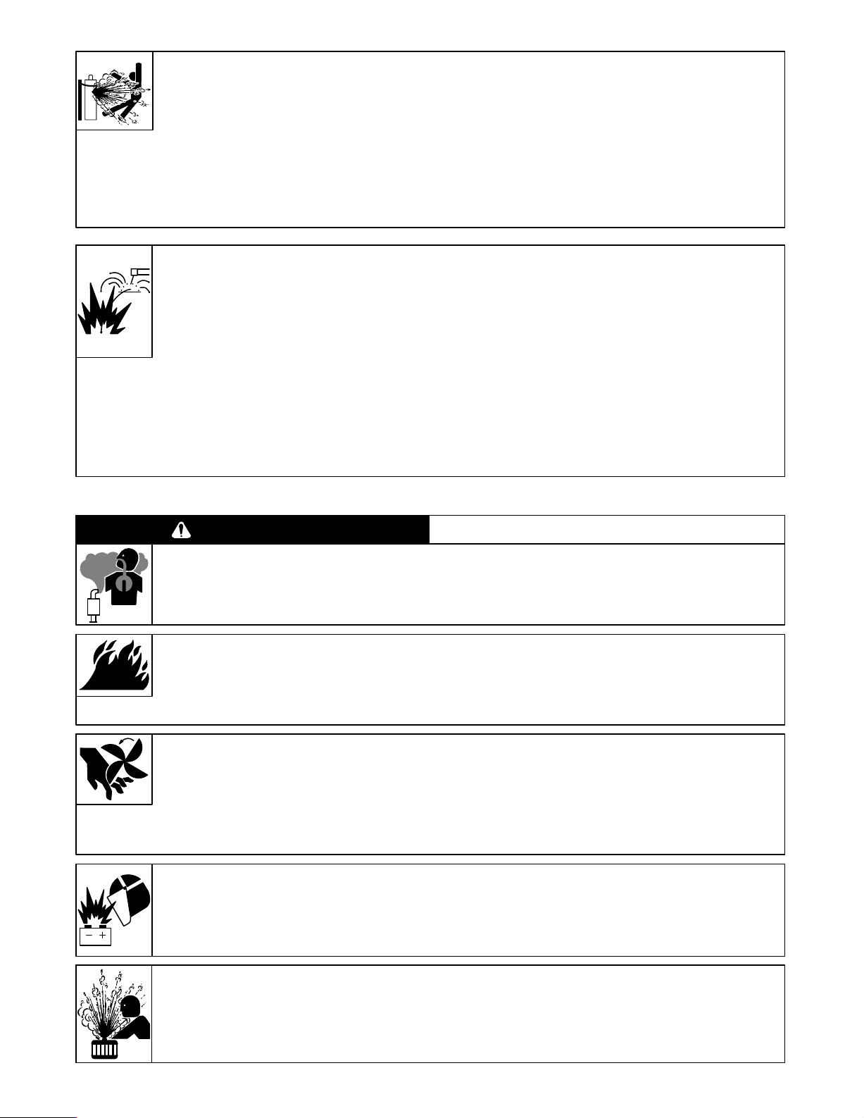
ELECTRIC SHOCK can kill.
Touching live electrical parts can cause fatal
shocks or severe burns. The electrode and work
circuit
is electrically live whenever the
The input power circuit and machine internal
circuits are also live when power is on. In
semiautomatic
wire reel, drive roll housing, and all metal parts
touching the welding wire are electrically live.
Incorrectly installed or improperly grounded
equipment
1.
Do not touch live electrical parts.
2. W
ear dry
, hole-free insulating gloves and body protection.
3. Insulate yourself from work and ground using dry insulating
mats
or covers big enough to prevent any
the
work or ground.
4. Disconnect input power or stop engine before installing or
servicing
to
5. Properly install and ground this equipment according to its
Owner’s
6. Always
power cord ground wire is properly connected to ground
this equipment. Lockout/tagout input power
OSHA 29 CFR 1910.147 (see Safety Standards).
Manual and national, state, and local codes.
verify the supply ground – check and be
or automatic wire welding, the wire,
is a hazard.
output is on.
physical contact with
according
sure that input
ARC RAYS can burn eyes and skin;
NOISE can damage hearing; FLYING
SLAG OR SPARKS can injure eyes.
Arc
rays from the welding process produce intense
visible and invisible (ultraviolet and infrared) rays
that can burn eyes and skin. Noise from some
processes can damage hearing. Chipping,
grinding, and welds cooling throw off pieces of
metal
NOISE
1.
Use approved ear plugs or ear muf
or slag.
fs if noise level is high.
terminal in disconnect box or that cord plug is connected to a
properly
grounded receptacle outlet.
7. When making input connections, attach proper grounding
conductor
8. Frequently
replace
9. T
urn of
10. Do not use worn, damaged, undersized, or poorly spliced
cables.
11. Do
earth grounding of the workpiece is required,
12. If
with
13. Do not touch electrode if you are in contact with the work,
ground,
14. Use only well-maintained equipment. Repair or replace
damaged
15. W
16.
Keep all panels and covers securely in place.
17. Clamp work cable with good metal-to-metal contact to
workpiece
ARC RAYS
2. Wear a welding helmet fitted with a proper shade of filter to
protect
Z49.1
3. W
4. Use protective screens or barriers to protect others from flash
and
5. Wear protective clothing made from durable, flame-resistant
material
first – double-check connections.
inspect input power cord for damage or bare wiring –
cord immediately if damaged – bare wiring can kill.
f all equipment when not in use.
not drape cables over your body
a separate cable – do not use work clamp or work cable.
or another electrode from a dif
parts at once. Maintain unit according to manual.
ear a safety harness if working above floor level.
or worktable as near the weld as practical.
your face and eyes when welding or
and Z87.1 listed in Safety Standards).
ear approved safety glasses with side shields.
glare; warn others not to watch the arc.
(wool and leather) and foot protection.
.
ground it directly
ferent machine.
watching (see ANSI
FUMES AND GASES can be hazardous
to your health.
Welding produces fumes and gases. Breathing
these fumes and gases can be hazardous to your
health.
1. Keep
2. If inside, ventilate the area and/or use exhaust at the arc to
3.
4. Read the Material Safety Data Sheets (MSDSs) and the
your head out of the fumes. Do not breathe the fumes.
remove
welding fumes and gases.
If ventilation is poor
manufacturer’s instruction for metals, consumables, coatings,
cleaners,
and degreasers.
, use an approved air-supplied respirator
.
5. Work in a confined space only if it is well ventilated, or while
wearing an air-supplied respirator. Always have a trained
watchperson
and
lower the oxygen level
breathing
6. Do
not weld
operations.
form
7. Do not weld on coated metals, such as galvanized, lead, or
cadmium plated steel, unless the coating is removed from the
weld area, the area is well ventilated, and if necessary, while
wearing
containing
nearby
. W
elding fumes and gases can displace air
air is safe.
in locations near degreasing, cleaning, or spraying
The
highly toxic and irritating gases.
heat and rays of the arc can react with vapors to
an air-supplied respirator
these elements can give of
causing injury or death. Be sure the
. The coatings and any
f toxic fumes if welded.
OM-175 104 Page 1
metals
CYLINDERS can explode if damaged.
Shielding gas cylinders contain gas under high
pressure. If damaged, a cylinder can explode.
Since
gas cylinders are normally part of the welding
process,
be sure to treat them carefully
1. Protect compressed gas cylinders from excessive heat,
mechanical shocks, slag, open flames, sparks, and arcs.
2. Install
3. Keep cylinders away from any welding or other electrical
cylinders in an upright position by securing
support
or cylinder rack to prevent falling or tipping.
circuits.
.
to a stationary
4. Never
5.
6.
7. Use
8. Turn
9. Keep
10. Read and follow instructions on compressed gas cylinders,
drape a welding torch over a gas cylinder
Never allow a welding electrode to touch any cylinder
Never weld on a pressurized cylinder – explosion will result.
only correct shielding gas cylinders, regulators, hoses, and
fittings
designed for the specific application; maintain them and
associated
in
use or connected for use.
associated
Standards.
parts in good condition.
face away from valve outlet when opening cylinder valve.
protective cap in place over valve except when cylinder is
equipment, and CGA publication P-1
.
.
listed in Safety
WELDING can cause fire or explosion.
Welding on closed containers, such as tanks,
drums,
or pipes, can cause them to blow up. Sparks
can fly off from the welding arc. The flying sparks,
hot workpiece, and hot equipment
and
burns. Accidental contact of electrode to
objects
can cause sparks, explosion, overheating,
or fire. Check and be sure the area is safe before
doing
any welding.
1.
Protect yourself and others from flying sparks and hot metal.
2. Do
not weld where flying sparks can strike flammable material.
3. Remove
4. Be
5. Watch
all flammables within
this
is not possible, tightly cover them with approved covers.
alert that welding sparks and hot materials from welding can
easily go
through
small cracks and openings to adjacent areas.
for fire, and keep a fire extinguisher nearby
35 ft (10.7 m) of the welding arc. If
1-3. Engine Hazards
WARNING
ENGINE EXHAUST GASES can kill.
Engines
produce harmful exhaust gases.
ENGINE FUEL can cause fire or
explosion.
Engine
fuel is highly flammable.
1. Stop
engine and let it cool of
f before checking or adding fuel.
can cause fires
metal
.
aware that welding on a ceiling, floor
6. Be
can cause fire on the hidden side.
7. Do not weld on closed containers such as tanks, drums, or
pipes,
unless they are properly prepared according to A
(see
Safety Standards).
8. Connect
9.
10. Remove stick electrode from holder or cut off welding wire at
11. Wear
12. Remove
1.
2. If used in a closed area, vent engine exhaust outside and
2. Do
3.
4. Do not spill fuel. If fuel is spilled, clean up before starting
work cable to
practical
to prevent welding current from
unknown
Do not use welder to thaw frozen pipes.
contact
shirt, cuf
from
paths and causing electric shock and fire hazards.
tip when not in use.
oil-free protective garments such as leather gloves,
fless trousers, high shoes, and a cap.
any combustibles,
your person before doing any welding.
Use equipment outside in open, well-ventilated areas.
from any building air intakes.
away
not add fuel while smoking or
open
flames.
Do not overfill tank – allow room for fuel to expand.
engine.
the work as close to the welding area as
such as a butane lighter or matches,
, bulkhead, or partition
WS F4.1
traveling long, possibly
heavy
if unit is near any sparks or
MOVING PARTS can cause injury.
Moving
parts, such as fans, rotors, and belts can
cut
fingers and hands and catch loose clothing.
1. Keep all doors, panels, covers, and guards closed and
2.
in place.
securely
Stop engine before installing or connecting unit.
SPARKS
can cause BA
TTERY
GASES
TO EXPLODE; BATTERY ACID can
burn eyes and skin.
Batteries contain acid and generate explosive
gases.
STEAM AND PRESSURIZED HOT
COOLANT can burn face, eyes, and
skin.
It is best to check coolant level when engine is
cold
to avoid scalding.
OM-175 104 Page 2
3. Have only qualified people remove guards or covers for
maintenance
4. To prevent accidental starting during servicing, disconnect
negative
5. Keep
parts.
6. Reinstall
finished
1. Always
2. Stop engine before disconnecting or connecting battery
cables.
not allow tools to cause sparks when working on a battery
3. Do
not
4. Do
5. Observe
1. If
the engine is warm and checking
and
3.
2. W
ear safety glasses and gloves and put a rag over cap.
3. Turn cap slightly and let pressure escape slowly before
completely
and troubleshooting as necessary
(–) battery cable from battery
hands, hair
and before starting engine.
wear a face shield when working on a battery
use welder to charge batteries or jump start vehicles.
, loose clothing, and tools away from
panels or
correct polarity (+ and –) on batteries.
guards and close doors when servicing is
removing cap.
.
is needed, follow steps 2
.
moving
.
.
1-4. Additional Installation, Operation, And Maintenance Hazards
WARNING
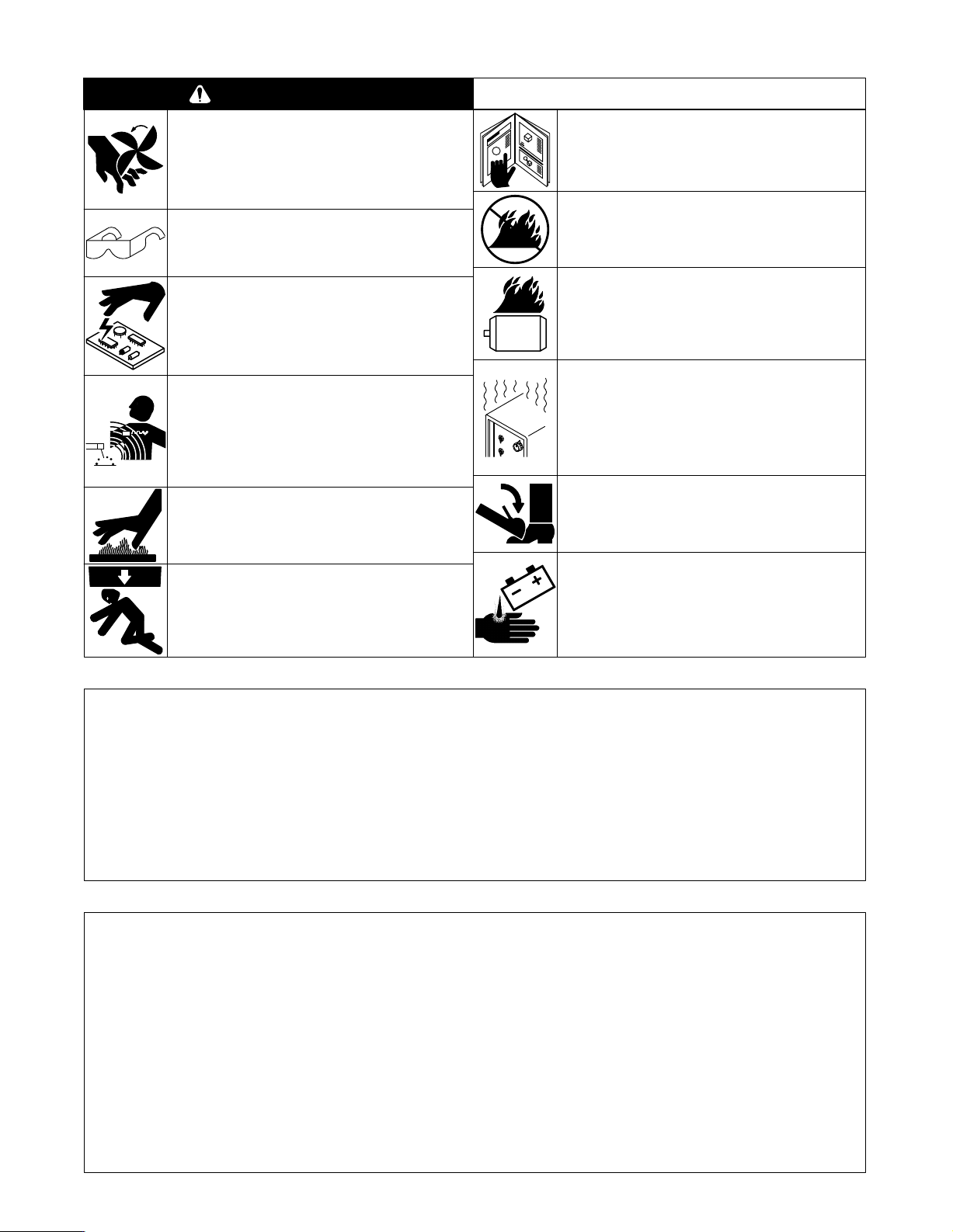
MOVING PARTS can cause injury.
1. Before
2. Block
working
or injectors to keep engine from kicking back or
starting.
flywheel so that it will not
on
generator components.
of generator
, remove spark plugs
turn while working
FLYING PIECES OF METAL or DIRT can
injure eyes.
1. Wear safety glasses with side shields or face
shield.
STATIC ELECTRICITY can damage parts
on circuit boards.
1. Put on grounded wrist strap BEFORE handling
boards
or parts.
2. Use proper static-proof bags and boxes to store,
or ship PC boards.
move,
MAGNETIC FIELDS FROM HIGH
CURRENTS can affect pacemaker
operation.
1. Pacemaker wearers keep away.
earers should consult their doctor before going
2. W
near arc welding, gouging, or spot welding
operations.
HOT PARTS can cause severe burns.
1. .Allow
2. Wear
cooling period before maintaining.
protective gloves and clothing when working
on
a hot engine.
READ INSTRUCTIONS.
1. Use
only genuine MILLER replacement parts.
2. Reinstall injectors and bleed air from fuel system
according to engine manual.
DO NOT LET ENGINE EXHAUST SPARKS
CAUSE FIRE.
1. Use approved engine exhaust spark arrestor in
areas – see applicable codes.
required
LOW VOLTAGE AND FREQUENCY CAN
DAMAGE electrical equipment such as
MOTORS.
1. Turn off or unplug equipment before starting or
stopping
engine.
OVERUSE can cause OVERHEATED
EQUIPMENT.
1. Allow
2. Reduce current or reduce duty cycle before
3.
cooling period.
starting
to weld again.
Follow rated duty cycle.
TILTING OF TRAILER can cause injury.
1. Use
tongue jack or blocks to support weight.
2. Properly install welding generator onto trailer
according
to instructions supplied with trailer
.
FALLING EQUIPMENT can cause serious
personal injury and equipment damage.
1. Use lifting eye to lift unit only, NOT running gear,
gas cylinders, or any other accessories.
Use equipment of adequate capacity to lift unit.
2.
1-5. Principal Safety Standards
Safety
in W
Welding Society, 550 N.W. LeJeune Rd, Miami FL 33126
elding and Cutting
Safety and Health Standards
Superintendent of Documents, U.S. Government Printing Office,
Washington, D.C. 20402.
Recommended Safe Practices for the Preparation for Welding and
Cutting of Containers That Have Held Hazardous Substances
American Welding Society Standard AWS F4.1, from American
Welding Society, 550 N.W. LeJeune Rd, Miami, FL 33126
National Electrical Code
Protection Association, Batterymarch Park, Quincy, MA 02269.
, ANSI Standard
, OSHA 29 CFR 1910, from
, NFPA Standard 70, from National Fire
Z49.1, from American
1-6. EMF Information
Considerations About Welding And The Effects Of Low Frequency
Electric And Magnetic Fields
The
following
the U.S. Congress, Office of Technology Assessment,
Effects
Paper
Office,
findings
with animals and people which clearly establish that low frequency
magnetic
systems.
complex. Current scientific understanding does not yet allow us to
interpret the evidence in a single coherent framework. Even more
frustrating,
questions of possible risk or to offer clear science-based advice on
strategies to minimize or avoid potential risks.”
is a quotation from the General Conclusions Section of
of Power Frequency Electric & Magnetic Fields – Background
, OTA-BP-E-53 (Washington, DC: U.S. Government Printing
May 1989): “. . . there is now a
based on experiments at the cellular level and from studies
fields can
While most of this work is of very high quality
interact with, and produce changes in, biological
it does not yet allow us to draw definite conclusions about
very large volume of scientific
Biological
, the results are
BATTERY ACID can BURN SKIN AND
EYES.
1. Do
not tip.
2.
Replace damaged battery
3.
Flush eyes and skin immediately with water
Safe Handling of Compressed Gases in Cylinders
P-1, from Compressed Gas Association, 1235 Jefferson Davis
Highway, Suite 501, Arlington, VA 22202.
Code
for Safety in W
Canadian Standards Association, Standards Sales, 178 Rexdale
Boulevard, Rexdale, Ontario, Canada M9W 1R3.
S
,
afe Practices For Occupation And Educational Eye And Face
Protection
Institute, 1430 Broadway, New York, NY 10018.
Cutting
Fire Protection Association, Batterymarch Park, Quincy, MA 02269.
To reduce magnetic fields in the workplace, use the following
procedures:
1. Keep cables close together by twisting or taping them.
2. Arrange cables to one side and away from the operator.
3. Do not coil or drape cables around the body.
4. Keep welding power source and cables as far away as
5. Connect work clamp to workpiece as close to the weld as
About Pacemakers:
The above procedures are also recommended for pacemaker
wearers. Consult your doctor for complete information.
,
ANSI Standard Z87.1, from American National Standards
And
practical.
possible.
elding and
W
elding Processes
Cutting
, NFP
.
, CGA Pamphlet
, CSA Standard W1
A Standard 51B, from National
.
17.2, from
OM-175 104 Page 3
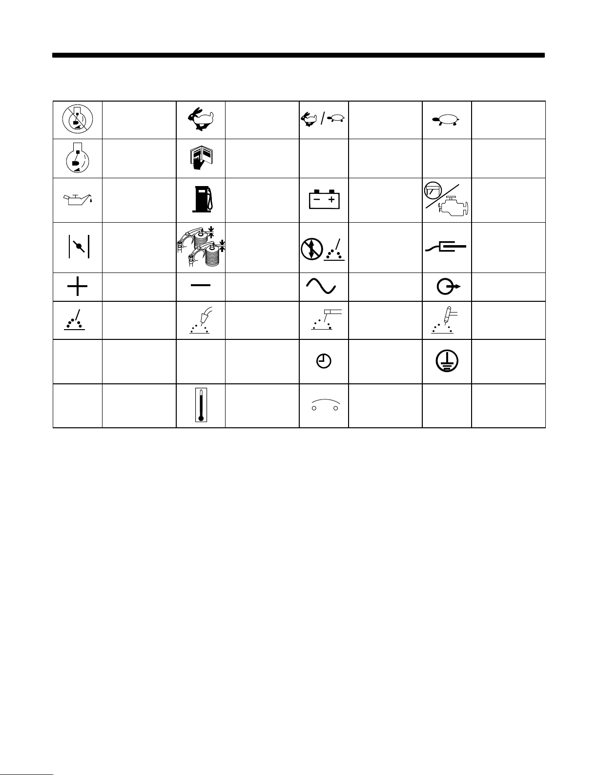
2-1. Symbol Definitions
SECTION 2 – DEFINITIONS
h
Stop
Engine
Start Engine
Engine Oil
Engine Choke
Positive Negative
W
elding Arc
(Electrode)
Hours
(Run, W
Read Operator
Check Valve
Clearance
Gas Metal Arc
elding (GMA
W
Seconds Time
s
Fast
eld/Power)
Manual
Fuel
Wire
W),
Fast/Slow
(Run/Idle)
’s
A
Amperes
Battery (Engine)
Do not switch
while welding
Alternating Current
(AC)
Shielded Metal Arc
W
elding (SMA
W),
Stick
V
Slow (Idle)
Volts
Engine
W
ork Connection
Output
Gas T
ungsten Arc
W
elding (TIG)
Protective Earth
(Ground)
Temperature Circuit Breaker
OM-175 104 Page 4
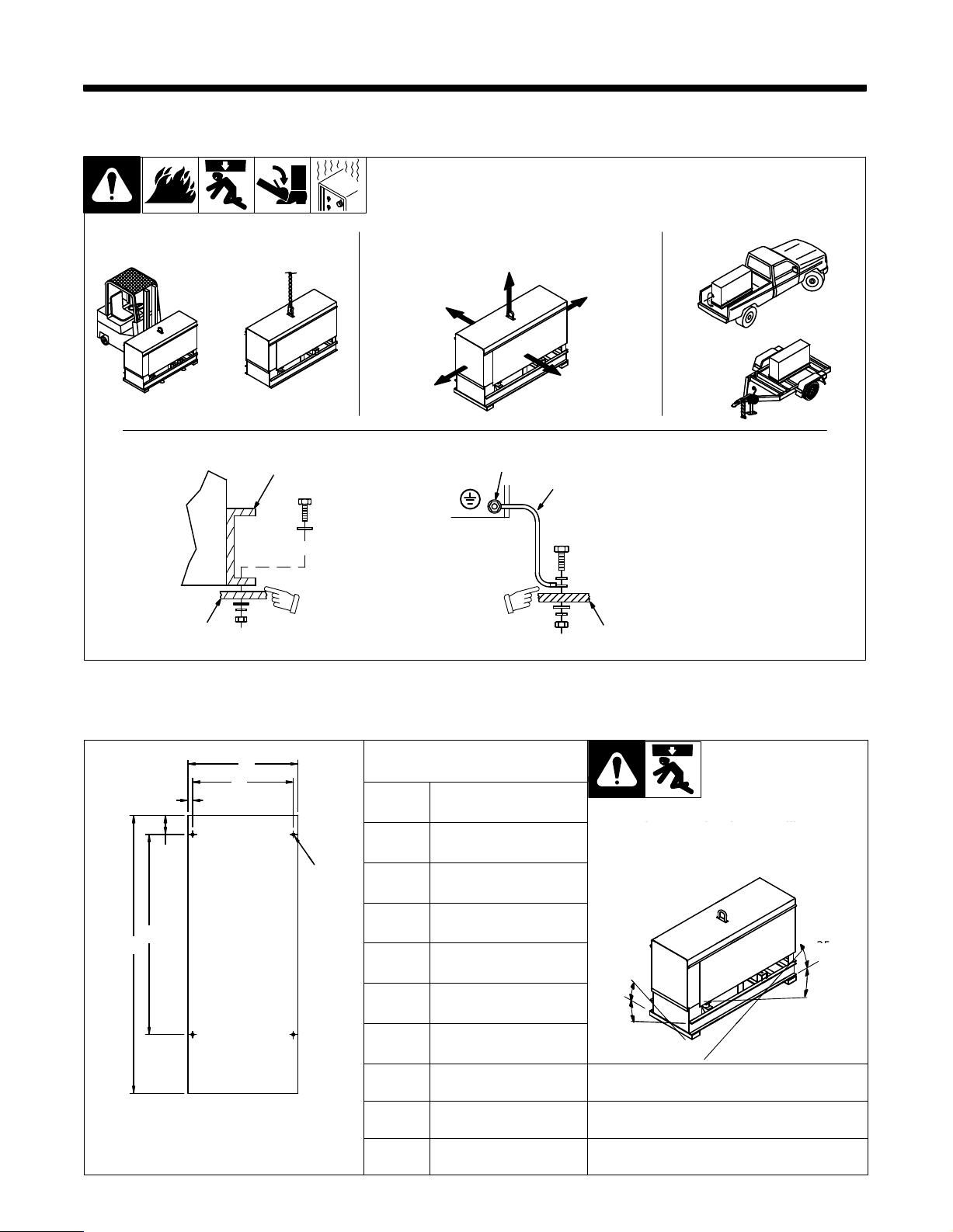
SECTION 3 – INSTALLATION
Do not exceed operating angles while
E
3-1. Installing Welding Generator
Movement Airflow Clearance Location
18 in
OR
(460 mm)
18 in
(460 mm)
18 in
(460 mm)
OR
18 in
(460 mm)
Grounding
1
Electrically
OR
bond
generator frame to
3
GND/PE
vehicle frame by metal-to-metal
2
contact.
3-2. Dimensions, Weights, And Operating Angles
A
B
C
D
G
4 Holes
Height
Width
Depth
Dimensions
31 in (787 mm)
18-3/4 in (476 mm)
46 in (1
164 mm)
18 in
(460 mm)
1 Generator Base
2
Metal V
ehicle Frame
3
4
2
install1* 3/96 – Ref. ST-800 652 / Ref. ST-800 477-A / ST-158 936-A / S-0854
Do not exceed operating angles while
running
Do
not move or operate unit where it could
tip.
Equipment Grounding
Terminal
4
Grounding Cable
Use #10 AWG or larger insulated
wire.
copper
or engine damage will occur
.
E
F
Engine End
ST-800 426
A
B
C
D
E
F
G
18 in (457 mm)
16-1/2 in (419 mm)
3/4 in (19 mm)
3-1/8 in (79 mm)
32-3/4 in (832 mm)
45-1/2 in (1
13/32 in (10 mm) Dia.
156 mm)
25°
25°
Weight
Net: 567 lb (258 kg)
Ship: 608 lb (276 kg)
OM-175 104 Page 5
25°
°
25°
angles_1 3/96
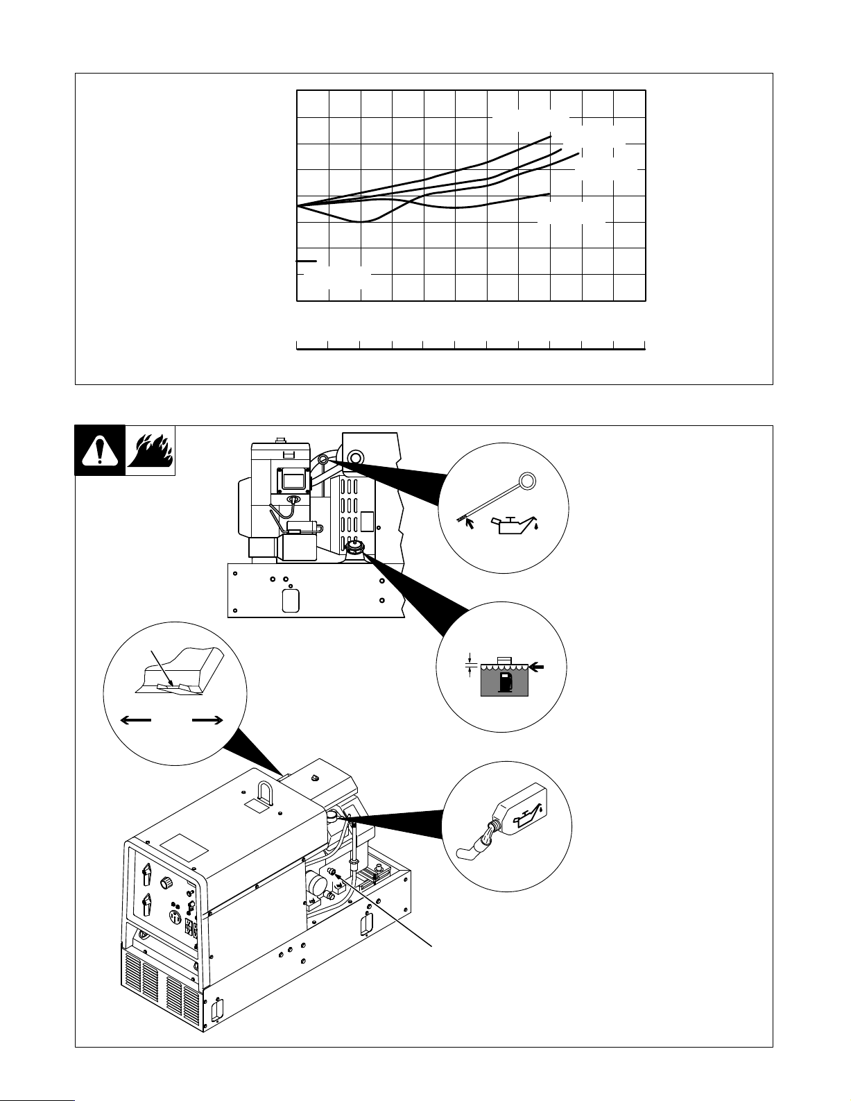
3-3. Fuel Consumption
7.57
6.62
5.67
4.73
3.78
2.84
1.89
0.95
LITERS/HR.
1.67
1.46
1.25
1.04
0.84
0.63
0.42
0.21
IMP. GAS/HR.
2.0
1.8
1.5
1.3
1.0
0.8
0.5
0.3
0.0
0 25 50 75 100 125 150 175 200 225 250 275
U.S. GAL/HR.
0 1.0 2.0 3.0 4.0 5.0 6.0 7.0 8.0 9.0 10.0 11.0
3-4. Engine Prestart Checks
IDLE
2200 RPM
AUX POWER
3750 RPM
3750 RPM
CV WELD
3750 RPM
WELD AMPERES AT 100% DUTY CYCLE
POWER KVA AT 100% DUTY CYCLE
Full
DC WELD
AC WELD
3750 RPM
Ref. SB-179 939
Check
all fluids daily
be
cold and on a level surface. Unit
is
shipped with 10W30 engine oil.
1
Low Oil Pressure Shutdown
Switch
Engine stops if oil pressure gets
low
.
too
2
Anti-Icing Control
Use control to prevent carburetor
in cold weather
icing
. Engine must
.
2
Below Above
45°F
(7°C)
1
1/2 in
(13 mm)
Full
Gasoline
OM-175 104 Page 6
Ref. ST-801 188-A / Ref. ST-801 221
Loading...