


 Loading...
TECHNICAL INFORMATION
CVA615 Coffee System
© 2007 Miele USA

CVA615 Coffee System
Technical Information
CVA615 Coffee System – Table of Contents
1.0 |
Construction and Design......................................................................... |
9 |
||
|
1.1 |
Appliance Overview................................................................................... |
9 |
|
|
|
1.1.1 |
Front View...................................................................................... |
9 |
|
|
1.1.2 |
Controls ....................................................................................... |
10 |
|
|
1.1.3 Interior (Front of Appliance Opened) ........................................... |
10 |
|
|
1.2 |
Technical Data........................................................................................ |
11 |
|
|
1.3 |
Layout of Components ........................................................................... |
12 |
|
2.0 |
Installation .............................................................................................. |
|
13 |
|
3.0 |
Commission and Operation .................................................................. |
14 |
||
|
3.1 |
General Operation ................................................................................... |
14 |
|
|
|
3.1.1 |
Preparing Coffee.......................................................................... |
14 |
|
|
3.1.2 |
Canceling the Preparation ........................................................... |
15 |
|
|
3.1.3 |
Steam Control.............................................................................. |
15 |
|
|
3.1.4 |
Hot Water..................................................................................... |
16 |
|
|
3.1.5 Adjusting the Coffee Grinder ....................................................... |
17 |
|
|
|
3.1.6 Filling the Coffee Beans Container .............................................. |
18 |
|
|
|
3.1.7 Filling the Water Tank.................................................................. |
19 |
|
4.0 |
Description of Function......................................................................... |
20 |
||
|
4.1 |
Door Switch ............................................................................................. |
20 |
|
|
4.2 |
Overflow (Reed) Switch........................................................................... |
20 |
|
|
4.3 |
Brew Unit – Cleaning and Care ............................................................... |
21 |
|
|
4.4 |
Brew Unit Removal from the Appliance................................................... |
21 |
|
|
4.5 |
Connection of Brew Unit to Drive Mechanism ......................................... |
22 |
|
|
4.6 |
Brewing Procedure .................................................................................. |
23 |
|
|
4.7 |
Grounds Container .................................................................................. |
26 |
|
|
4.8 |
Waste Unit Present Switch ...................................................................... |
26 |
|
|
4.9 |
Water Tank .............................................................................................. |
28 |
|
|
4.10 |
Water Level Switch.................................................................................. |
29 |
|
|
4.11 |
Grinder Assembly .................................................................................... |
31 |
|
|
4.12 |
Grinder – Overload Protection................................................................. |
33 |
|
|
4.13 |
Ground Coffee Dispensing ...................................................................... |
35 |
|
|
4.14 |
Dispenser Switch..................................................................................... |
36 |
|
|
4.15 |
Brew Unit Drives...................................................................................... |
37 |
|
|
4.16 |
Water Pump............................................................................................. |
39 |
|
|
4.17 |
Flow Meter............................................................................................... |
39 |
|
|
4.18 |
Heaters .................................................................................................... |
39 |
|
|
4.19 |
Flow Through Heaters ............................................................................. |
40 |
|
|
4.20 |
Water Path............................................................................................... |
42 |
|
|
|
4.20.1 |
Water Intake ............................................................................... |
43 |
|
|
4.20.2 |
Water Path - Coffee .................................................................... |
43 |
2

CVA615 Coffee System
Technical Information
CVA615 Coffee System – Table of Contents (continued)
|
|
4.20.3 Water Path – Hot Water.............................................................. |
43 |
|
|
4.20.4 Water Path – Steam ................................................................... |
43 |
|
4.21 |
Water Valve ............................................................................................. |
44 |
|
4.22 |
Electronic Assemblies ............................................................................. |
45 |
|
|
4.22.1 Power Electronic.......................................................................... |
45 |
|
|
4.22.2 CPU Electronic ............................................................................ |
46 |
5.0 |
Service and Maintenance ...................................................................... |
47 |
|
|
5.1 |
Lid - Removal .......................................................................................... |
47 |
|
5.2 |
Interference Suppression Filter (Z1) - Removal ...................................... |
48 |
|
5.3 |
Rear Panel - Removal ............................................................................. |
48 |
|
5.4 |
Adjustment Slide Switch Frame - Removal ............................................. |
49 |
|
5.5 |
Door Contact Switch (S24) - Removal..................................................... |
50 |
|
5.6 |
Base Plate - Removal.............................................................................. |
51 |
|
5.7 |
Drip Tray - Removal ................................................................................ |
52 |
|
5.8 |
Overflow Switch Actuator Float - Removal .............................................. |
53 |
|
5.9 |
Overflow Switch (B8/3) - Removal........................................................... |
54 |
|
5.10 |
Rear Door Panel - Removal .................................................................... |
55 |
|
5.11 |
Fascia Panel Cover - Removal................................................................ |
56 |
|
5.12 |
Selector Switch - Removal ...................................................................... |
57 |
|
5.13 |
Display Module Electronic - Removal...................................................... |
58 |
|
5.14 |
Coffee Dispensing Nozzle - Removal...................................................... |
59 |
|
5.15 |
Coffee Dispensing Nozzle - Installation................................................... |
60 |
|
5.16 |
Steam Valve and Steam Valve Switch (S79) - Removal ......................... |
61 |
|
5.17 |
Hot Water Nozzle - Removal ................................................................... |
62 |
|
5.18 |
Hot Water Valve (Y12) - Removal ........................................................... |
62 |
|
5.19 |
Checking Temperature at Coffee Dispenser ........................................... |
63 |
|
5.20 |
Brew Unit – Removal (in Start/Home Position)........................................ |
64 |
|
5.21 |
Brew Unit – Removal (NOT in Start/Home Position) ............................... |
65 |
|
5.22 |
Brew Unit - Installation............................................................................. |
67 |
|
5.23 |
Brew Unit – Cleaning Procedure ............................................................. |
67 |
|
5.24 |
Brew Unit – Filter Cleaning...................................................................... |
68 |
|
5.25 |
Brew Unit – Degreasing via the Rinse Cycle........................................... |
69 |
|
5.26 |
Brew Unit - Lubrication ............................................................................ |
71 |
5.27Brew Unit – Manual Reset to “Home Position” (with Brew Unit Not
|
Installed in Appliance) ............................................................................. |
72 |
5.28 |
Brew Unit Creamer Valve - Removal....................................................... |
73 |
5.29 |
Brew Unit Handle - Removal ................................................................... |
73 |
5.30 |
Brew Unit Funnel - Removal.................................................................... |
74 |
5.31 |
Brew Unit Ram - Service ......................................................................... |
75 |
5.32 |
Brew Unit Drives - Service....................................................................... |
77 |
5.33 |
Water Tank Float - Removal.................................................................... |
82 |
5.34 |
Water Tank Lip Seal - Removal............................................................... |
83 |
5.35 |
Lower Section of Tank Valve - Removal ................................................. |
84 |
5.36 |
Beans Container - Removal .................................................................... |
86 |
3

CVA615 Coffee System
Technical Information
CVA615 Coffee System – Table of Contents (continued)
|
5.37 |
Beans Container Guide - Removal.......................................................... |
87 |
|
5.38 |
Grinder - Disassembly ............................................................................. |
88 |
|
5.39 |
Grinder Assembly – Basic Setting ........................................................... |
91 |
|
5.40 |
Grinder Unit - Removal............................................................................ |
92 |
|
5.41 |
Dispensing Solenoid - Removal .............................................................. |
93 |
|
5.42 |
Dispenser Switch - Removal ................................................................... |
93 |
|
5.43 |
Waterpath & Flowmeter - Testing............................................................ |
94 |
|
5.44 |
Water Path Leakage Test........................................................................ |
96 |
|
5.45 |
Water Path Connections - Opening......................................................... |
97 |
|
5.46 |
Water Path Connections - Closing .......................................................... |
97 |
6.0 |
Fault Diagnosis ...................................................................................... |
98 |
|
|
6.1 |
Programming Mode ................................................................................. |
98 |
|
6.2 |
Service Mode........................................................................................... |
99 |
|
6.3 |
Displayed Messages ............................................................................. |
101 |
|
6.4 |
Fault Diagnosis...................................................................................... |
103 |
4

CVA615 Coffee System
Technical Information
CVA615 Coffee System – List of Figures
Figure 1-1: |
Front Overview CVA615............................................................................... |
9 |
Figure 1-2: |
CVA Controls.............................................................................................. |
10 |
Figure 1-3: |
Interior View of CVA615 with Door Opened ............................................... |
10 |
Figure 1-4: |
CVA615 Product Dimensions ..................................................................... |
11 |
Figure 1-5: |
CVA615 Overhead View of Components ................................................... |
12 |
Figure 2-1: |
Operating Manual....................................................................................... |
13 |
Figure 3-1: |
Cup Under the Dispensing Ports ................................................................ |
14 |
Figure 3-2: |
Pressing the Coffee Button......................................................................... |
14 |
Figure 3-3: |
Displayed Message .................................................................................... |
14 |
Figure 3-4: |
Canceling the Preparation Process ............................................................ |
15 |
Figure 3-5: |
Steam Selector........................................................................................... |
15 |
Figure 3-6: |
Placement of Cup Under the Hot Water Dispenser.................................... |
16 |
Figure 3-7: |
Hot Water Button ........................................................................................ |
16 |
Figure 3-8: |
Grinder Controls ......................................................................................... |
17 |
Figure 3-9: |
Adding Coffee Beans.................................................................................. |
18 |
Figure 4-1: |
Door Contact Switch (S24) ......................................................................... |
20 |
Figure 4-2: |
Brew Unit in “Home” Position ..................................................................... |
21 |
Figure 4-3: |
Brew Unit Connections ............................................................................... |
22 |
Figure 4-4: |
Brew Unit Filters ......................................................................................... |
23 |
Figure 4-5: |
Brew Unit Components............................................................................... |
24 |
Figure 4-6: |
Brew Unit, Showing Compressed Coffee “Puck”........................................ |
25 |
Figure 4-7: |
Waste Unit Present Switch ......................................................................... |
26 |
Figure 4-8: |
Waste Unit.................................................................................................. |
27 |
Figure 4-9: |
Water Tank................................................................................................. |
28 |
Figure 4-10: Water Level Switch..................................................................................... |
29 |
|
Figure 4-11: Water Level Switch Float............................................................................ |
29 |
|
Figure 4-12: Grinder Assembly ....................................................................................... |
31 |
|
Figure 4-13: Components of the Grinder Overload Protection ....................................... |
33 |
|
Figure 4-14: Ball Positions into the Grinder Cone, Under Different Operating |
|
|
|
Conditions................................................................................................... |
34 |
Figure 4-15: Coffee Dispensing Components................................................................. |
35 |
|
Figure 4-16: Dispensing Lever........................................................................................ |
36 |
|
Figure 4-17: Components of the Brew Unit Drive Assembly, Water Connection and |
|
|
|
Present Switch............................................................................................ |
37 |
Figure 4-18: Brew Unit Drive Assembly .......................................................................... |
38 |
|
Figure 4-19: Hot Water / Coffee Heater .......................................................................... |
40 |
|
Figure 4-20: Steam Heater ............................................................................................. |
41 |
|
Figure 4-21: Water Path.................................................................................................. |
42 |
|
Figure 4-22: Water Valve (Disassembled) ...................................................................... |
44 |
|
Figure 4-23: Power Electronic Board .............................................................................. |
45 |
|
Figure 4-24: CPU (Control) Electronic ............................................................................ |
46 |
|
5

CVA615 Coffee System
Technical Information
CVA615 Coffee System – List of Figures (continued)
Figure 5-1: |
Lid with Screws........................................................................................... |
47 |
Figure 5-2: |
Interference Suppression Filter (Z1) Mounting Location ............................ |
48 |
Figure 5-3: |
Rear Panel Removal .................................................................................. |
48 |
Figure 5-4: |
Removing the Adjustment Slide Switch Frame (Bezel) .............................. |
49 |
Figure 5-5: |
Door Switch (Shown with Appliance Door in Open Position) ..................... |
50 |
Figure 5-6: |
Base Plate - Removal................................................................................. |
51 |
Figure 5-7: |
Drip Tray Removal...................................................................................... |
52 |
Figure 5-8: |
Overflow Switch Actuator Float .................................................................. |
53 |
Figure 5-9: |
Overflow Switch.......................................................................................... |
54 |
Figure 5-10: Rear Door Panel - Removal ....................................................................... |
55 |
|
Figure 5-11: Fascia Panel Cover Assembly.................................................................... |
56 |
|
Figure 5-12: Selector Switch........................................................................................... |
57 |
|
Figure 5-13: Rear View of Front Door with Rear Panel Removed .................................. |
58 |
|
Figure 5-14: Components of the Coffee Dispensing Nozzle........................................... |
59 |
|
Figure 5-15: Components of Steam Valve and Steam Valve Switch.............................. |
61 |
|
Figure 5-16: Hot Water Valve Components .................................................................... |
62 |
|
Figure 5-17: Brew Unit .................................................................................................... |
66 |
|
Figure 5-18: Brew Unit Connection Socket Retaining Screw and Locking Tab .............. |
66 |
|
Figure 5-19: Brew Unit – Removal for Cleaning ............................................................. |
67 |
|
Figure 5-20: Brew Unit Installation.................................................................................. |
68 |
|
Figure 5-21: Cleaning Tablet being Placed into the Brew Unit Funnel ........................... |
69 |
|
Figure 5-22: Brew Unit Lubrication Points ...................................................................... |
71 |
|
Figure 5-23: Brew Unit Lubrication Points ...................................................................... |
71 |
|
Figure 5-24: Moving the Brew Unit to “Home Position”................................................... |
72 |
|
Figure 5-25: Brew Unit in Reset Position ........................................................................ |
72 |
|
Figure 5-26: Brew Unit – Highlighting the Output Assembly (Covering the Cream Valve) |
||
|
and Retaining Lugs for Securing the Handle to the Brew Unit Body .......... |
73 |
Figure 5-27: Rear of the Brew Unit, Highlighting the Funnel Lock.................................. |
74 |
|
Figure 5-28: Front of Brew Unit, Showing Spring Location and Holder .......................... |
74 |
|
Figure 5-29: Releasing the Ram from the Bottom of the Brew Unit................................ |
75 |
|
Figure 5-30: Brewing Unit Chamber Inside the Brew Unit Assembly.............................. |
76 |
|
Figure 5-31: Ram Assembly ........................................................................................... |
76 |
|
Figure 5-32: Front Plate Assembly with Retaining Screw Locations .............................. |
78 |
|
Figure 5-33: Grinder Retaining Screws........................................................................... |
79 |
|
Figure 5-34: Grinder Retaining Nuts............................................................................... |
79 |
|
Figure 5-35: Upper Front Plate Assembly Retaining Screws.......................................... |
80 |
|
Figure 5-36: Using a Suitable Item to Keep the Front Plate Assembly Elevated to Access |
||
|
the Screws at the Bottom ........................................................................... |
81 |
Figure 5-37: Removing the Cap to Access the Float in the Water Container ................. |
82 |
|
Figure 5-38: Levering Off the Lip Seal Cap .................................................................... |
83 |
|
Figure 5-39: Removing the Lip Seal ............................................................................... |
83 |
|
Figure 5-40: Water Tank Lip Seal Removal.................................................................... |
84 |
|
Figure 5-41: Underside View of the CVA615 with Base Plate and Drip Tray Removed . 85 |
||
Figure 5-42: Removing the Beans Container.................................................................. |
86 |
|
6

CVA615 Coffee System
Technical Information
CVA615 Coffee System – List of Figures (continued) |
|
Figure 5-43: Beans Container Guide .............................................................................. |
87 |
Figure 5-44: Grinder - Disassembly ................................................................................ |
88 |
Figure 5-45: Grinder........................................................................................................ |
89 |
Figure 5-46: Grinder - Apart............................................................................................ |
90 |
Figure 5-47: Grinder Removal ........................................................................................ |
92 |
Figure 5-48: Grinder Coupling ........................................................................................ |
93 |
Figure 5-49: Test Jumper Position.................................................................................. |
95 |
Figure 5-50: Display While in Service Mode ................................................................... |
95 |
Figure 5-51: Water Path Connection .............................................................................. |
97 |
7

|
CVA615 Coffee System |
Technical Information |
|
CVA615 Coffee System – List of Tables |
|
Table 6-1: Programming Mode Navigation .................................................................. |
98 |
Table 6-2: Service Mode Navigation.......................................................................... |
100 |
Table 6-3: Displayed Messages (Continued on Table 6-4) ....................................... |
101 |
Table 6-4: Displayed Messages (Continued from Table 6-3) .................................... |
102 |
8
CVA615 Coffee System
Technical Information
1.0Construction and Design
1.1Appliance Overview
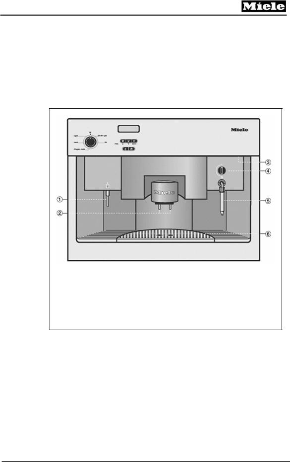
1.1.1Front View
1Hot Water Dispenser
2Coffee Dispensers (Height-Adjustable)
3Handle to Open Appliance Front
4Steam Selector
5Steam Nozzle with Milk Frother
6Drip Catch
Figure 1-1: Front Overview CVA615
9
CVA615 Coffee System
Technical Information
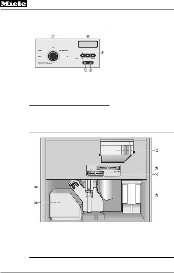
1.1.2Controls
7Program Selector
8Message Window
9Coffee Serving Buttons
10Rinse / Pre-Warm Button
11Hot Water Button
Figure 1-2: CVA Controls
1.1.3Interior (Front of Appliance Opened)
12Coffee Bean Container
13Slide Control to Select Fineness of Ground Coffee
14Slide Control to Select Quantity of Ground Coffee
15Water Tank
16Waste Unit
17Brew Unit
Figure 1-3: Interior View of CVA615 with Door Opened
10
CVA615 Coffee System
Technical Information
1.2Technical Data
Product Dimensions
Figure 1-4: CVA615 Product Dimensions
Electrical Information
The appliance comes equipped with a 6ft (1.8 m) power cord with a NEMA 5-15P molded plug for connection to a 120 V, 15 A, 60 Hz power supply.
11
CVA615 Coffee System
Technical Information
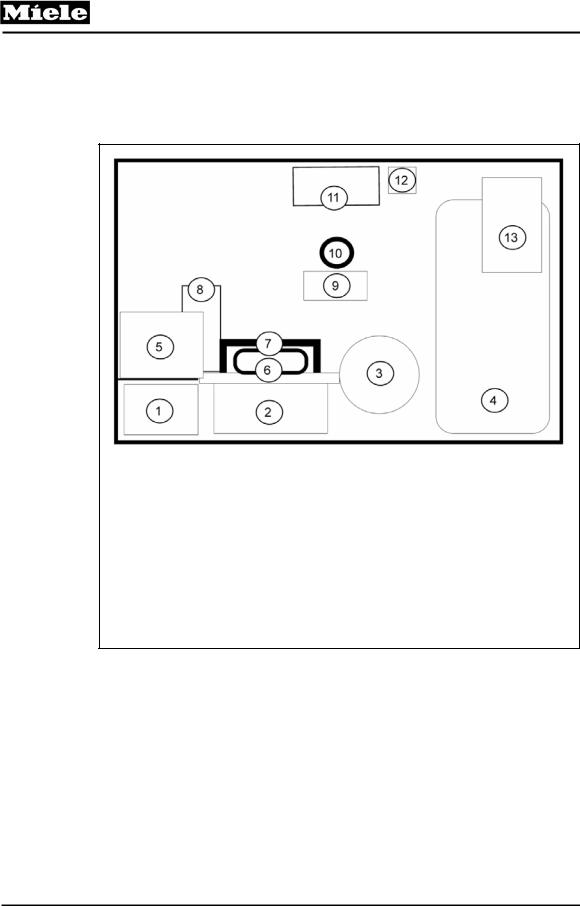
1.3Layout of Components
Overhead View of Main Components
1Waste Container
2Brew Unit
3Grinder
4Water Tank
5CPU Electronic Board
6Drive Assembly (Mounted to Wall)
7Drive Assembly Cover
8Hot Water / Coffee Heater
9Water Pump
10Flowmeter
11Steam Heater
12Steam Solenoid Valve
13Power Electronic Board
Figure 1-5: CVA615 Overhead View of Components
12

CVA615 Coffee System
Technical Information
2.0Installation
Refer to the Installation section of the Operating Manual.
Figure 2-1: Operating Manual
13
CVA615 Coffee System
Technical Information
3.0Commission and Operation
3.1General Operation
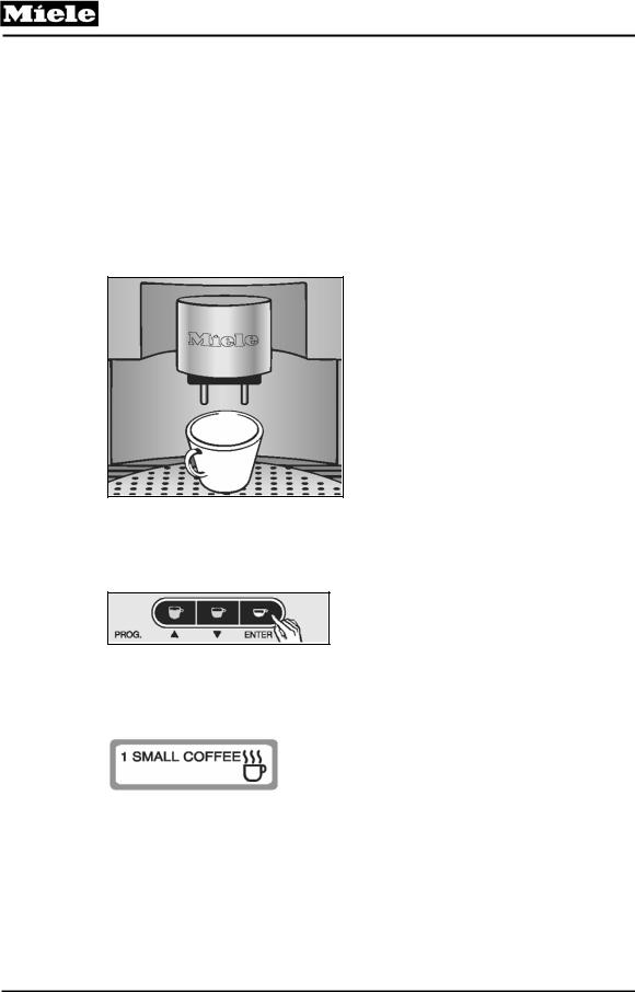
3.1.1Preparing Coffee
1. Place a cup under both coffee dispensing ports.
Figure 3-1: Cup Under the Dispensing Ports
2.Press the desired size coffee button once. This will start the preparation cycle.
Figure 3-2: Pressing the Coffee Button
The following message will appear in the message window, depending on the button pressed:
Figure 3-3: Displayed Message
14
CVA615 Coffee System
Technical Information
3.1.2Canceling the Preparation
Press any one of the coffee buttons to stop preparation immediately.
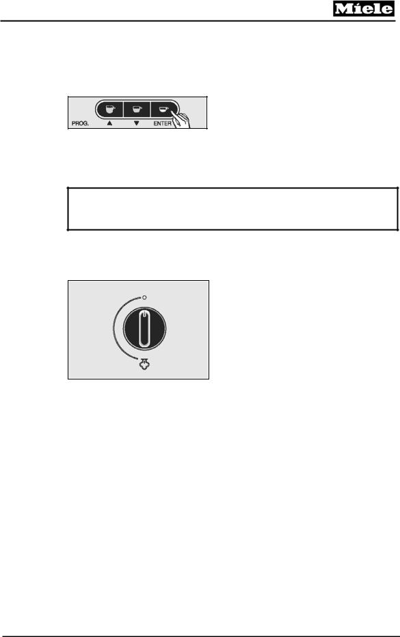
Figure 3-4: Canceling the Preparation Process
3.1.3Steam Control
Caution:
The steam from the appliance is extremely hot; use caution to prevent burns.
•Turn the steam ON by turning the Steam Selector counter-clockwise.
•Turn the steam OFF by turning the Steam Selector clockwise.
Figure 3-5: Steam Selector
15
CVA615 Coffee System
Technical Information
3.1.4Hot Water
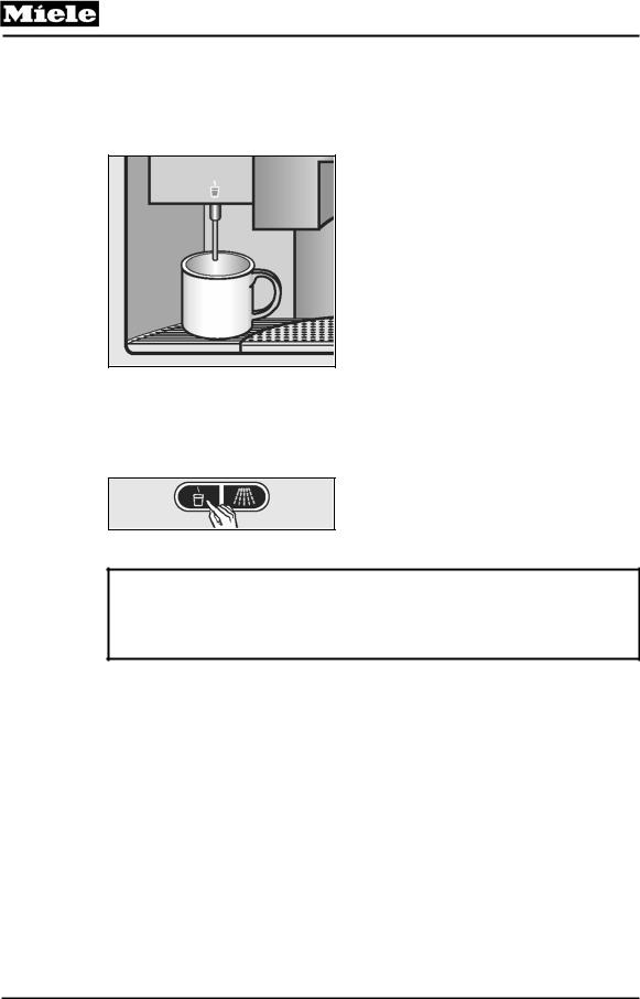
1. Place a cup under the hot water dispenser.
Figure 3-6: Placement of Cup Under the Hot Water Dispenser
2.Press the hot water button. Hot water will be dispensed.
3.Press the hot water button again to stop the flow of hot water.
Figure 3-7: Hot Water Button
Note:
If programmed with the hot water feature activated…
The flow of hot water will stop automatically once a predetermined amount of hot water has passed through the system
16
CVA615 Coffee System
Technical Information
3.1.5Adjusting the Coffee Grinder
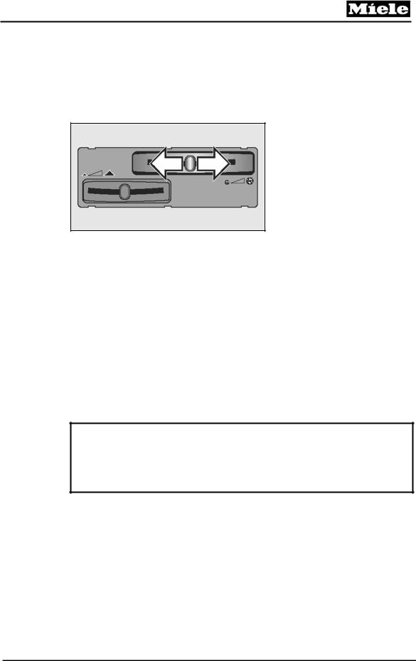
Controls
Slide to the left for finer grinding.
Slide to the right for coarser grinding.
Figure 3-8: Grinder Controls
If the espresso flows too quickly into the cup, the beans may have been ground too coarsely. The grinder should be adjusted to a finer setting.
If the espresso only trickles into the cup, the beans may have been ground too fine and the coffee will be bitter. The grinder should be adjusted to a coarser setting.
If the crema is evenly colored but pale, the ground coffee is too coarse.
If the crema is very dark brown on one side, graduating almost to white on the other, the ground coffee is too fine.
Note:
You should be able to feel notches when moving the slide control.
If the slide control will not move:
Close the machine and dispense a cup of coffee. Then try to move the slide control again.
17
CVA615 Coffee System
Technical Information
3.1.6Filling the Coffee Beans Container
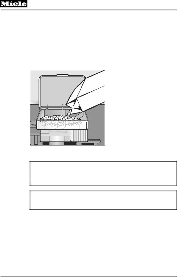
1.Open the appliance door.
2.Carefully slide the container out so that the lid is visible.
3.Lift the lid.
4.Fill the container with coffee beans to about 1" from the top.
5.Close the lid and push the container back into place.
6.Shut the appliance door.
Figure 3-9: Adding Coffee Beans
Important!
Only put whole espresso or coffee beans in the container. Anything else, including ground coffee, hot cocoa, instant coffee, or treated coffee beans (flavorings, caramel, or sugar) will damage the grinder.
Note:
Do not remove the coffee bean container from the appliance unless it is completely empty, otherwise coffee beans will spill out.
18

CVA615 Coffee System
Technical Information
3.1.7Filling the Water Tank
The water tank must be washed and filled with fresh drinking water each day. A reminder will appear in the message window when the unit is first turned on.
1.Open the front of the machine.
2.Lift the water tank up and out of the appliance.
3.Open the lid and fill the container with cold drinking water to within about 1" (2 cm) of the top.
Important!
Never add hot water or any other liquid except cold water to the water tank.
4.Close the lid and place the tank in the machine, pushing it straight back.
5.Close the front of the appliance.
19
CVA615 Coffee System
Technical Information
4.0Description of Function
4.1Door Switch
The door switch, removes power to the appliance when the door is opened. Refer to Figure 4-1 – Door Contact Switch (S24).
Figure 4-1: Door Contact Switch (S24)
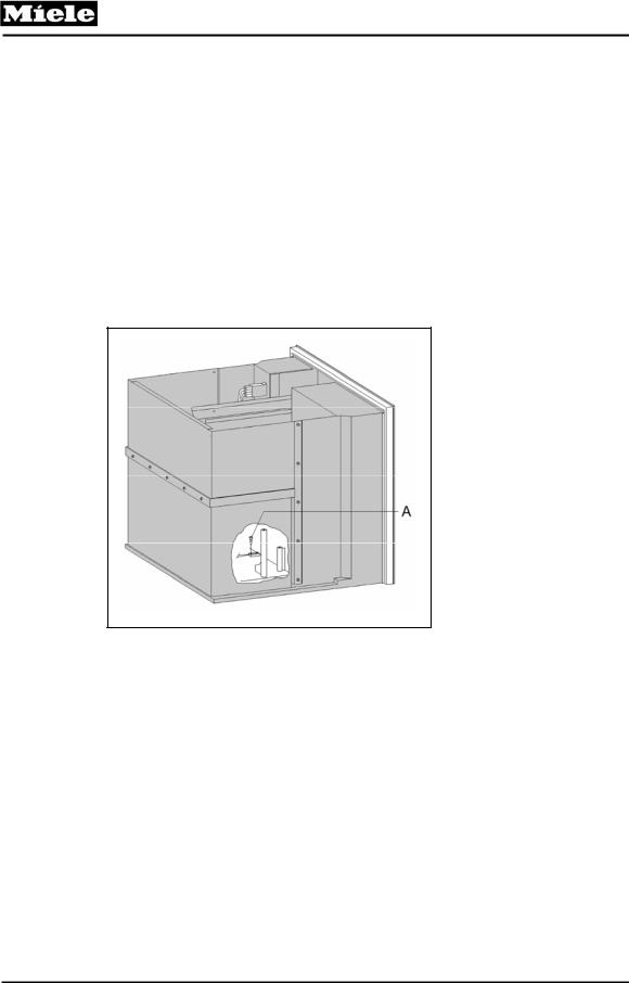
4.2Overflow (Reed) Switch
The overflow switch is in the lower section of the appliance case.
The float with magnet is located in the drip tray. Should a leak develop, water flows into the drip tray. The float with magnet then rises and activates the overflow reed switch which in turn causes the electronic control to switch the unit off.
Note:
When the Service Mode is accessed, the top line of the display shows the switches that are activated. An “A” will be displayed if the Overflow Switch is actuated. (i.e. water present in the bottom of the appliance)
Refer to Section 6 for more information on the Service Mode.
20
CVA615 Coffee System
Technical Information
4.3Brew Unit – Cleaning and Care
The Brew Unit is a mechanically operated component that is subjected to high forces. After a long period of use, the Brew Unit may become clogged. To ensure correct operation of the Brew Unit, it is essential to clean it regularly and apply silicone grease to the moving parts. Refer to Section 5.0 – Service and Maintenance for further information and procedures.
4.4Brew Unit Removal from the Appliance
The brew unit must be in the home position (refer to Figure 4-2) before it can be removed from the appliance.
Figure 4-2: Brew Unit in “Home” Position
21
CVA615 Coffee System
Technical Information
4.5Connection of Brew Unit to Drive Mechanism
1Drive Shaft Socket
2Water Connection Socket
3Locking Mechanism Switch Lug
4Brew Unit Switch
5Water Nozzle
6Drive Shaft
Figure 4-3: Brew Unit Connections
Operation
Refer to Figure 4-3 – Brew Unit Connections.
When the Brew Unit is placed into in the appliance, it locks into position. The locking mechanism Switch Lug (Item 3), activates the Brew Unit Switch (Item 4). The Drive Shaft (Item 6) engages with the Brew Unit Drive Shaft Socket (Item 1). The Nozzle (Item 5), supplies the Brew Unit with hot water under pressure. When the Brew Unit is in the brewing position, the socket (Item 2), allows hot water to pass through the coffee.
22
CVA615 Coffee System
Technical Information
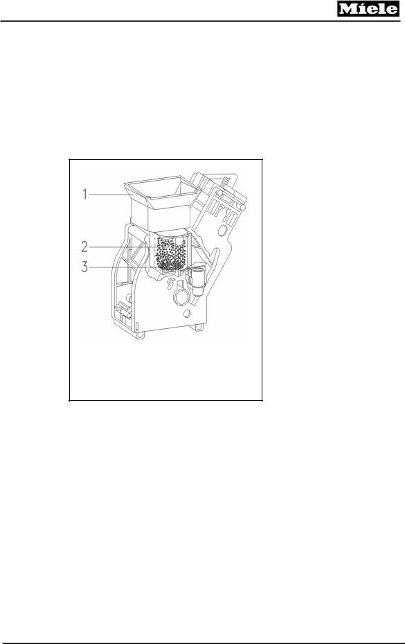
4.6Brewing Procedure
1.The grinder fills the dispenser housing until full (as determined by the dispenser switch).
2.The grinder is then switched off.
3.The dispenser flap opens twice (two clicks) via the dispenser solenoid assembly.
4.The ground coffee then falls into the brew unit via the funnel.
1Funnel
2Percolator Chamber
3Bottom Filter
Figure 4-4: Brew Unit Filters
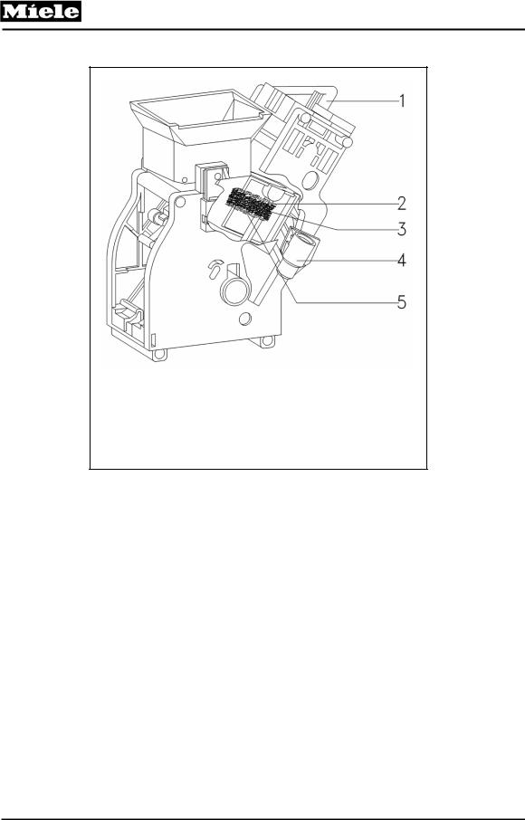
Refer to Figure 4-5 – Brew Unit Components.
5.The drive tilts the percolator chamber and raises it to the brewing position. The ground coffee is compressed between the Top Filter (Item 2) and Bottom Filter (Item 5).
6.Water then flows through the Water Nozzle Socket, (Item 4). The pump forces the hot water through the Brew Unit and the compressed grounds (Pos 3). Coffee exits the top of Brew Unit via the Outlet (Item 1).
23
CVA615 Coffee System
Technical Information
1Outlet
2Top Filter
3Compressed Coffee
4Water Nozzle Socket
5Bottom Filter
Figure 4-5: Brew Unit Components
24
CVA615 Coffee System
Technical Information
Refer to Figure 4-6 – Brew Unit, Showing Compressed Coffee “Puck”.
7.As the drive begin to move back toward the starting (home) position the coffee chamber moves upward and releases the used compressed coffee grounds (puck). Pos. 1.
8.The drive continues and returns the brew unit to its starting (home) position.
Figure 4-6: Brew Unit, Showing Compressed Coffee “Puck”
25
CVA615 Coffee System
Technical Information
4.7Grounds Container
After coffee has been prepared, the coffee grounds compressed puck falls into the waste container. The electronic monitors the number of the compressed pucks. After a specific amount is reached, the message “Empty waste unit” is displayed.
4.8Waste Unit Present Switch
A reed switch is mounted to the bottom of the housing – as shown in the Figure 4-7.
Figure 4-7: Waste Unit Present Switch
26
CVA615 Coffee System
Technical Information
The actuating magnet (Figure 4-8, Item 1) for the Waste Unit switch is fitted in the bottom edge of the container. The electronic monitors whether the waste unit is installed.
1 Magnet for Present Switch Actuation
Figure 4-8: Waste Unit
When the appliance is placed into the Service Mode, the top line of the display shows the switches that have been activated. A “5” is displayed when the Waste Unit is installed and the switch is actuated. For further information, refer to Section 6 – Service Mode.
Note:
On newer Waste Units, an additional magnet has been installed that assists in keeping the waste unit attached to the metal frame inside the appliance.
27
CVA615 Coffee System
Technical Information
4.9Water Tank
Refer to Figure 4-9 – Water Tank.
The Water Tank holds the water required for the brewing of the coffee, hot water and steam. When the Water Tank is installed, the sealing ring is pressed upwards allowing water to flow out.
1 Valve Assembly
Figure 4-9: Water Tank
When the tank is removed from the unit, the spring closes the sealing ring to ensure water cannot flow from the tank when it is out of the appliance for filling etc…
28
CVA615 Coffee System
Technical Information
4.10Water Level Switch
The Water Level Switch is located within the housing (as shown in Figure 4-10, Item 1).
Figure 4-10: Water Level Switch
The actuating magnet for the Water Level Switch is located in the Water Tank as shown below (Figure 4-11, Item 1).
Figure 4-11: Water Level Switch Float
29

CVA615 Coffee System
Technical Information
When the water tank is installed, and contains at least 30-33 ounces of water; the Water Level Switch is activated and its contacts close.
If the water quantity drops below the minimum quantity, the water level switch is no longer activated and the contacts open.
After the switch opens, the water passing through the water pump is registered via the flowmeter and recorded by the electronic unit as up to 27 ounces of water is still available.
After the 27 ounces is calculated as being used, the display shows “Fill water tank”. To prevent the water pump from running dry, about 3 – 7 ounces of water remains in the tank.
If the appliance is placed into the service mode the top line of the display shows the switches that have been activated. A “7” is displayed when the water tank is installed and filled with water. Refer to section 6 – Service Mode for further information.
30
Loading...