


www.mgeups.com
P
O
T
S
L
L
I
W
G
N
I
H
T
O
N
MGE UPS SYSTEMS
Pulsar Evolution
2200/3000/3000 XL
Installation and user manual
N |
O |
W |
O |
U |
|
Y
34007115EN/AA - Page 1

Page 2 - 34007115EN/AA

Introduction
Thank you for selecting an MGE UPS SYSTEMS product to protect your electrical equipment.
The Pulsar Evolution range has been designed with the utmost care. We recommend that you take the time to read this manual to take full advantage of the many features of your UPS.
MGE UPS SYSTEMS pays great attention to the environmental impact of its products. Measures that have made Pulsar Evolution a reference in environmental protection include:
the eco-design approach used in product development,
recycling of Pulsar Evolution at the end of its service life.
To discover the entire range of MGE UPS SYSTEMS products and the options available for the Pulsar Evolution range, we invite you to visit our web site at www.mgeups.com or contact your MGE UPS SYSTEMS representative.
34007115EN/AA - Page 3
Foreword
Using this document
Information may be found in two ways, using:
the contents;
the index.
Pictograms
Important instructions that must always be followed.
Information, advice, help.
Visual indication.
Action.
Audio indication.
In the illustrations on the following pages, the symbols below are used:
LED off.
LED on.
LED flashing.
Page 4 - 34007115EN/AA

Contents
1.Presentation
1.1 |
Overall view ................................................................................................................................. |
7 |
|
Tower position ................................................................................................................................. |
7 |
|
Rack position .................................................................................................................................. |
7 |
1.2 |
Back ............................................................................................................................................. |
8 |
1.3 |
Control panel ................................................................................................................................. |
9 |
2.Installation
2.1 |
Unpacking and parts check ....................................................................................................... |
10 |
2.2 |
Upright installation (tower position) ......................................................................................... |
11 |
2.3 |
Flat installation (rack position) .................................................................................................. |
12 |
2.4 |
Connecting the protected equipment ....................................................................................... |
13 |
2.5 |
Connection to the RS232 or USB communications port (optional) ......................................... |
14 |
2.6 |
Connection to the data-line protection port (optional) ............................................................. |
14 |
2.7 |
Installation of the communications-card option ...................................................................... |
15 |
3.Operation
3.1 |
Start-up ........................................................................................................................................ |
16 |
3.2 |
Shift to booster or fader mode (during voltage variations in the AC-input power) ..................... |
16 |
3.3 |
Operation on battery power (following failure of AC-input power) ............................................. |
17 |
|
Transfer to battery power .............................................................................................................. |
17 |
|
Threshold for the low-battery warning ........................................................................................... |
17 |
3.4 |
Personalisation (optional) ........................................................................................................... |
18 |
|
Function ........................................................................................................................................ |
18 |
|
ON / OFF conditions tab ............................................................................................................... |
18 |
|
Battery tab ..................................................................................................................................... |
18 |
|
Voltage-thresholds tab .................................................................................................................. |
19 |
|
Sensitivity tab ................................................................................................................................ |
19 |
4.Maintenance
4.1 |
Trouble-shooting......................................................................................................................... |
20 |
4.2 |
Replacement of the battery module .......................................................................................... |
21 |
5. Environment ..................................................................................................................................... |
23 |
|
34007115EN/AA - Page 5

Contents
6.Appendices
6.1 |
Technical data ............................................................................................................................. |
24 |
|
Simplified diagram ........................................................................................................................ |
24 |
|
Technical characteristics ............................................................................................................... |
25 |
|
Examples of battery backup times ................................................................................................ |
26 |
6.2 |
Glossary....................................................................................................................................... |
27 |
6.3 |
Index............................................................................................................................................. |
28 |
Page 6 - 34007115EN/AA
1. Presentation
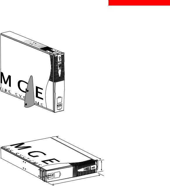
1.1 Overall view
Tower position
|
Dimensions in mm |
|
(W x H x D) |
Evolution 2200 |
438 x 87.9 x 640 |
Evolution 3000 |
(19") (2U) |
Evolution 3000 XL |
|
|
|
|
Weight in kg |
|
|
Evolution 2200 |
34 |
Evolution 3000 |
37 |
Evolution 3000 XL |
21 |
P U L |
S A R |
Evolution |
|
3 0 0 |
0 |
Rack position
D
H
P U L |
S A R |
Evolution |
|
3 0 0 |
0 |
W
34007115EN/AA - Page 7
1. Presentation
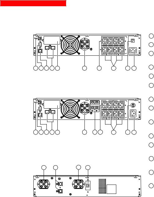
1.2 Back
Pulsar Evolution 2200 |
|
|
|
||||
RS232 |
DATA LINE |
PROTECTION |
|
|
|
||
|
|
|
|
|
|||
|
|
IN |
OUT |
|
|
|
|
|
TO BATTERY |
|
|
|
|
1 |
2 |
|
CABINET |
|
|
|
|
||
|
|
|
|
|
|
1 |
2 |
1 |
2 |
3 |
4 |
5 |
6 |
8 |
9 |
Us/Out/Ausg I max 10A |
Ue/In/Eing 230V/10A Max |
10 11
Pulsar Evolution 3000 / 3000 XL
RS232 |
DATA LINE |
PROTECTION |
||
|
|
|||
|
|
IN |
OUT |
|
|
TO BATTERY |
|
|
|
|
CABINET |
|
|
|
1 |
2 |
3 |
4 |
5 |
|
|
A |
B |
A |
|
B |
|
1 |
|
2 |
|
|
|
1 |
2 |
|
|
1 |
2 |
6 |
7 |
8 |
9 |
Us/Out/Ausg I max 13A |
Ue/In/Eing 230V/16A Max |
10 11
EXB additional battery module
12 |
13 |
12 |
14 |
1 USB communications port.
2RS232 communications port.
3Connector for automatic detection of an additional battery module.
4Data-line protection.
5Slot for communications-card option.
6Connector for an additional battery module.
7Output circuit breakers.
8Four outlets for direct connection of protected equipment.
9Two groups of two programmable outlets (groups 1 and 2).
10Input circuit-breaker.
11Socket for connection to AC-power source.
12Battery module connectors (to the UPS or to other battery modules).
13Connectors for automatic detection of additional battery modules.
14Circuit breaker for battery ON/OFF and protection.
Page 8 - 34007115EN/AA
1. Presentation
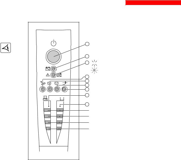
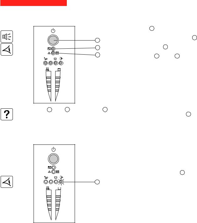
1.3 Control panel
15Iluminated ON/OFF button for the outlets.
16Operation on battery power.
17

 UPS fault.
|
|
Battery fault. |
|
18 |
Overload. |
1 |
19 |
Group 1 programmable outlets supplied with power. |
2 |
Group 2 programmable outlets supplied with power. |
|
|
20 |
|
|
21 |
Booster or fader mode. |
|
22 |
Bargraph indicating percent load at output. |
%
%
23 Bargraph indicating the battery charge level.
76 to 100%.
51 to 75%.
26 to 50%.
0 to 25%.
34007115EN/AA - Page 9

2. Installation
2.1 Unpacking and parts check
24 |
26 |
25
27
28
29
30
31
P |
U L |
S A R |
Evolution |
||
3 |
0 0 |
0 |
32
24Cord for connection to the AC-power source for 3000/3000 XL versions only (for the 2200 version, use the power cord of the protected equipment).
25Two cords for connection of the protected equipment.
26RS232 communications cable.
27USB communications cable.
28Telescopic rails for mounting in 19" bay with mounting hardware.
29Two securing systems for equipment power cords.
30CD-ROM with the Solution-Pac and UPS Driver software.
31Product documentation.
32Two supports for the upright position.
Page 10 - 34007115EN/AA
2. Installation
2.2 Upright installation (tower position)
Connect the two supports for the upright position.
P U L |
S A R |
|
|
Evolution |
|
3 0 0 |
0 |
n |
|
R o |
0 |
A t |
|
i |
|
S u |
0 |
L l |
0 |
o |
|
U v |
3 |
P E |
|
34007115EN/AA - Page 11
2. Installation
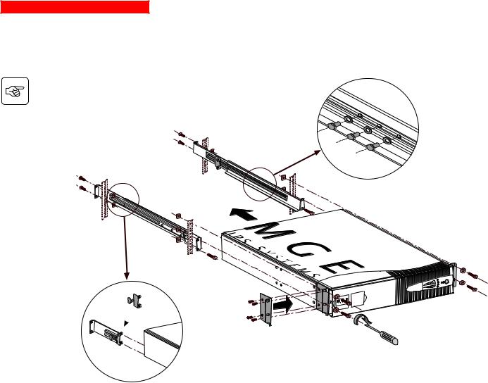
2.3 Flat installation (rack position)
Follow steps 1 to 6 for rack mounting of the UPS on the rails.
2 |
1 |
|
|
|
6 |
2 |
|
|
2 |
|
4 |
2
P U L |
S A R |
Evolution |
|
3 0 0 |
0 |
6 
5
3
3
5
The rails and the necessary mounting hardware are supplied by MGE UPS SYSTEMS.
Page 12 - 34007115EN/AA
2. Installation
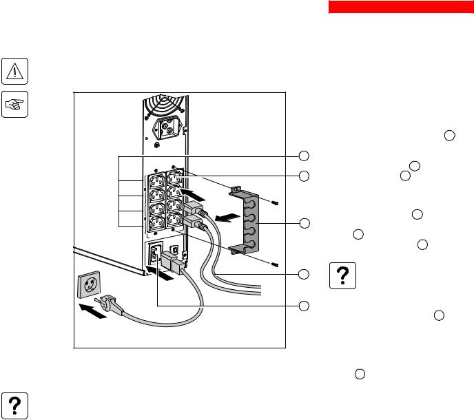
2.4 Connecting the protected equipment
Check that the indications on the rating plate on the back of the UPS correspond to your AC-power system and to the actual electrical consumption of all the equipment to be connected to the UPS.
|
|
|
|
1 - Remove the power cord supplying the |
|||||
|
|
|
|
equipment to be protected. |
|
|
|
|
|
|
|
|
|
2 - Pulsar Evolution 2200: Connect the |
|||||
|
|
|
|
power cord (1) just removed from the |
|
||||
|
|
|
|
equipment to the AC-power socket 11 and |
|||||
|
|
|
|
then to the AC-power wall outlet. |
|
|
|||
|
|
|
9 |
- Pulsar Evolution 3000/3000 XL: Connect |
|||||
|
|
|
|
the supplied power cord 24 |
(250 V, 16 A) to |
||||
|
|
|
8 |
the AC-power socket 11 and then to the |
|||||
1 |
|
|
|
AC-power wall outlet. |
|
|
|
|
|
1 |
|
|
|
|
|
|
|
|
|
|
|
|
|
|
|
|
|
|
|
|
|
|
|
3 - Connect the protected equipment to the |
|||||
2 |
|
|
|
UPS using the two cords 25 |
. It is advised |
||||
2 |
|
29 |
to connect priority loads to the four standard |
||||||
|
|
|
|||||||
|
|
Us/Out/Ausg |
10A |
outlets |
8 and any non-priority loads to the |
||||
|
|
I max |
|
|
|
|
|
|
|
|
|
|
|
four programmable outlets |
9 |
(in groups of |
|||
|
|
|
|
two outlets). |
|
|
|
|
|
|
|
230V/10A |
Max |
|
If the UPS is connected to a |
||||
|
|
|
|
||||||
|
|
|
25 |
|
computer running MGE |
|
|
||
|
|
|
|
|
communications software, it is |
||||
|
|
|
|
|
possible to program the |
|
|
||
|
|
|
11 |
|
interruption of power to the |
|
|||
|
|
|
|
|
programmable outlets |
9 |
during |
||
|
|
|
|
|
operation on battery power, thus |
||||
|
|
|
|
|
reserving backup power for the |
||||
|
|
|
|
|
priority loads. |
|
|
|
|
|
|
|
|
4 - Lock the connections using the securing |
|||||
|
|
|
|
system 29 . |
|
|
|
|
|
As soon as the UPS is energised, the battery begins charging. Eight hours are required to charge to the full rated backup time.
Pulsar Evolution 3000 XL: At least one EXB additional battery module must be connected to the UPS because it does not have internal batteries. See the EXB battery-module installation manual (Doc. no. 3400711600) for information on making the connections.
(1) Make sure the cord has the following characteristics: 250 V, 10 A, cross-sectional area 1 mm2, type HO5.
34007115EN/AA - Page 13
2. Installation
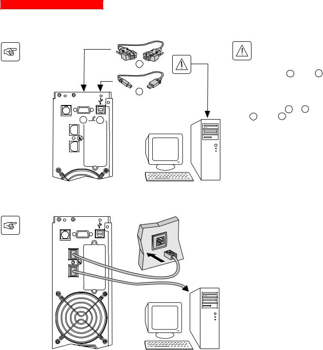
2.5 Connection to the RS232 or USB communications port (optional)
BATTERY TO CABINET
|
|
|
The RS232 and USB |
|
|
|
communications ports cannot |
|
|
|
operate simultaneously. |
|
|
|
26 |
|
|
|
1 - Connect the RS232 26 or USB 27 |
|
|
|
communications cable to the serial port or |
|
|
|
the USB port on the computer. |
|
|
|
27 |
|
RS232 |
|
2 - Connect the other end of the |
|
|
|
communications cable 26 or 27 to the |
|
2 |
1 |
RS232 2 or USB 1 communications |
|
port on the UPS. |
||
|
LINE DATA |
|
|
IN |
|
The UPS can now communicate with all |
|
OUT |
PROTECTION |
|
|
|
MGE UPS SYSTEMS supervision, set-up or |
||
|
|
|
safety software.
2.6 Connection to the data-line protection port (optional)
BATTERY TO CABINET |
RS232 |
IN |
LINE DATA |
OUT |
PROTECTION |
The data-line protection function on the UPS eliminates overvoltages flowing on the computer-network lines.
Simply connect the line to be protected to the UPS using the data-line protection connectors (IN and OUT) as indicated opposite (RJ45 cables not supplied).
Page 14 - 34007115EN/AA
2. Installation
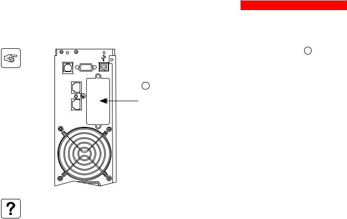
2.7 Installation of the communications-card option
BATTERY TO CABINET |
RS232 |
IN |
LINE DATA |
OUT |
PROTECTION |
|
|
1 |
- Remove the slot cover 5 secured by |
|
|
two screws. |
|
|
|
2 |
- Insert the card in the slot. |
|
5 |
3 |
- Secure the cover with the two screws. |
|
|||
Slot for the communications-card |
|
|
|
option. |
|
|
|
It is not necessary to shut down the UPS to install the communications card.
34007115EN/AA - Page 15
3. Operation
3.1 Start-up
 1 2
1 2
%
%
Press the ON / OFF button 15 .
The buzzer beeps and all the LEDs come ON.
The buzzer beeps twice during the self-test, then button 15 remains
15
ON, indicating that the outlets are supplied with power.
16- AC power is present: Only button 15 is ON. The protected equipment is supplied by the AC-power source.
17- AC power is absent: Button 15 and LED 16 are ON. The protected equipment is supplied by the UPS, operating on battery power.
All the connected equipment is supplied with power.
If button 15 or LED 16 are not ON or if LED 17 is ON, there is a fault (see section 4.1).
Note: The battery is charged as soon as the UPS is connected to the AC-power source, even if button 15 is in the OFF position.
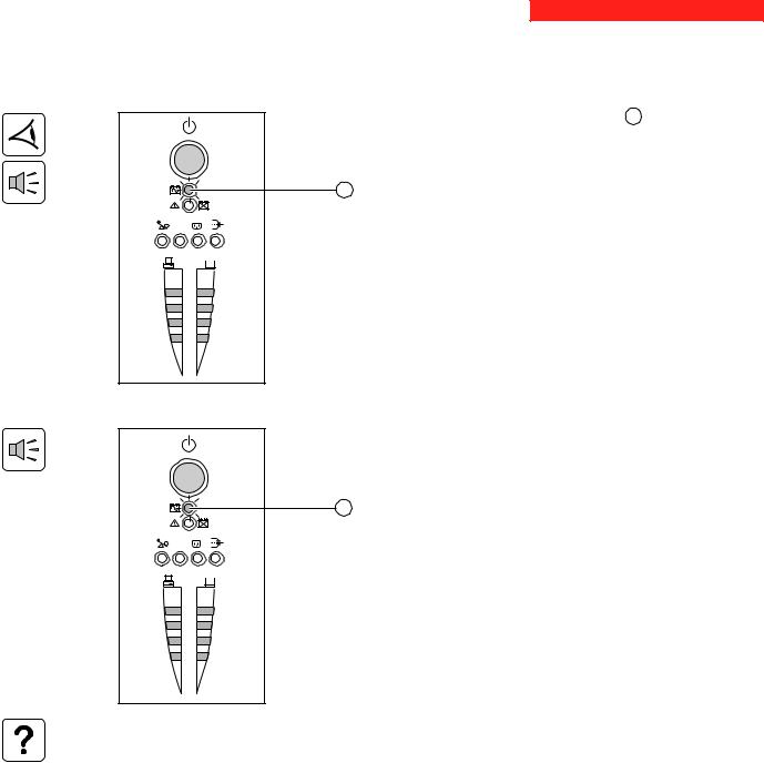
3.2 Shift to booster or fader mode
(during voltage variations in the AC-input power)
 1 2
1 2
21
%
%
The booster and fader functions maintain the output voltage supplied by the UPS within close tolerances around the rated value even if significant voltage variations occur in the AC-input power. This avoids calling on battery power.
The values defining the voltage range may be set using the UPS Driver software.
During operation in booster or fader mode, LED 21 is ON, signalling a significant voltage variation in the AC-input power.
Page 16 - 34007115EN/AA
3. Operation
3.3 Operation on battery power (following failure of AC-input power)
Transfer to battery power
The AC-input power is out of tolerances, LED 16 goes ON.
During operation on battery power, the buzzer beeps every ten seconds.
The equipment connected to the UPS is supplied by the battery.
16
 1 2
1 2
%
%
Threshold for the low-battery warning
 1 2
1 2
%
%
When the threshold is reached, the buzzer beeps every three seconds. The low-battery warning threshold can be set by the user, with the “UPS Driver” software.
There is very little remaining battery backup time. Close all
16applications because UPS automatic shutdown is imminent.
When the battery reaches the end of its backup time, the UPS shuts down and all the LEDs go OFF.
The equipment is no longer supplied with power.
The UPS automatically restarts when power returns.
If the UPS does not restart, check that the “automatic restart when power returns” function has not been disabled (see section 3.4 Personalisation).
34007115EN/AA - Page 17

3. Operation
3.4 Personalisation (optional)
Function
Personalisation parameters can be set and modified using the UPS Driver software installed on a computer that is connected to the UPS (see section 2.5 Connection to the RS232 communications port).
Check that the RS232 26 communications cable is connected.
UPS Driver installation:
1 - Insert the Solution-Pac CD-ROM containing the UPS Driver software in the drive of a PC running Windows. 2 - Open the Windows File manager or Explorer and select the CD-ROM drive.
3 - Double-click "\Emb\Evolutio\Config\Setup.exe".
Once UPS Driver has been installed, UPS parameters can be modified in a window containing a number of tabs, each presenting a set of parameters :
ON / OFF conditions tab
Configurable function |
Default setting |
Options |
|
|
|
Automatic restart |
Enabled |
Disabled |
|
|
|
Cold start |
Enabled |
Disabled |
|
|
|
Forced reboot |
Enabled |
Disabled |
|
|
|
Energy saving |
Disabled |
Enabled |
|
|
|
UPS ON / OFF via software |
Enabled |
Disabled |
|
|
|
Battery tab
Configurable function |
Default setting |
Options |
|
|
|
|
|
Every day |
Interval between automatic battery tests |
Once a week |
Once a month |
|
|
No test |
|
|
|
Low-battery warning threshold |
20% of the remaining battery |
10 to 40% of the remaining battery |
|
backup time |
backup time |
|
|
|
Configuration of additional battery modules |
Display the number of standard |
Back-up time for non-standard |
|
EXB modules connected |
batteries (for 3000XL only) |
|
to the UPS |
|
|
|
|
Protection against deep discharges |
Enabled |
Disabled |
|
|
|
Page 18 - 34007115EN/AA
 Loading...