


PULSAR 1000
www.mgeops.com
Pulsar
700 – 1000 – 1500
1000 RT2U – 1500 RT2U
EXB 1000/1500
EXB 1000/1500 RT2U
Installation and User Manual
Manuel d’installation et d’utilisation
Manual de instalación y de usuario
Manual de instalação e do usuário
ENGLISH
FRANÇAIS
ESPAÑOL
PORTUGUESE


Installation and User Manual
86-86700-00 A01
Pulsar
Installation and User Manual
Revision History
Pulsar Installation and User Manual, 86-86700-00
Revision: A01 ECN#: 005282 5/2007
Copyright © 2007 MGE Office Protection Systems
All rights reserved. Printed in U.S.A.
MGE Office Protection Systems
13 Whatney, Suite #101
Irvine, CA 92618
(949) 268-2800
For Technical Support, Customer Care Center, or Customer FAQ,
please visit our website: www.mgeops.com or call (800) 279-7776
ENGLISH

Pulsar
86-86700 A01
ENGLISH

Contents
Contents
c i
86-86700-00 A01
Introduction..........................................................................................................................................1
Symbol Usage ....................................................................................................................................3
1. Presentation
1.1 Standard Positions..........................................................................................................1 — 1
1.2 Rear Panels....................................................................................................................1 — 2
1.3 Control Panel..................................................................................................................1 — 3
2. Installation
2.1 Unpacking and Contents Check ....................................................................................2 — 1
2.2 Installation of the RT Model in Tower Position ..............................................................2 — 2
2.3 Installation of the RT Model in a Rack ..........................................................................2 — 2
2.4 Communication Ports ....................................................................................................2 — 3
2.5 Connection to the Communication Port by Contact (2)..................................................2 — 4
2.6 Connections with a FlexPDU module ............................................................................2 — 5
2.7 UPS Connection ............................................................................................................2 — 5
3. Operation
3.1 Start-Up and Normal Operation......................................................................................3 — 1
3.2 Operation on Battery Power ..........................................................................................3 — 1
3.3 Return of AC Power........................................................................................................3 — 2
3.4 UPS Shutdown ..............................................................................................................3 — 2
3.5 Using the UPS Remote Control Functions ....................................................................3 — 2
4. Access to Measurements and Personalization Data
4.1 Display Menus Arrangement ..........................................................................................4 — 1
4.2 Access to Measurements ..............................................................................................4 — 1
4.3 Personalization Using the Control Panel........................................................................4 — 1
4.4 Personalization Using External Software ......................................................................4 — 2
5. Maintenance
5.1 Troubleshooting ..............................................................................................................5 — 1
5.2 Battery-module Replacement ........................................................................................5 — 2
Appendices
6.1 Technical Specifications ................................................................................................A — 1
6.2 Programming the Programmable Outlets ......................................................................A — 2
MGE Office Protection Systems Customer Care Center ..............................................A — 4
Glossary ........................................................................................................................G — 1
ENGLISH

Pulsar
86-86700-00 A01
ENGLISH
Introduction
Thank you for selecting an MGE Office Protection Systems product to protect your electrical equipment.
Pulsar has been designed with the utmost care.
We recommend that you take the time to read this manual to take full advantage of the many features of your UPS (Uninterruptible
Power System).
Before installing Pulsar, please read the booklet on the required safety instructions. Then follow the indications in this manual.
To discover the entire range of MGE Office Protection Systems products and the options available for the Pulsar range, we invite
you to visit our web site at www.mgeops.com or contact your MGE Office Protection Systems representative.
Environmental protection
MGE Office Protection Systems has implemented an environmental-protection policy.
Products are developed according to an eco-design approach.
Substances
This product does not contain CFCs, HCFCs, or asbestos.
Packing
To improve waste treatment and facilitate recycling, separate the various packing components.
◗ The cardboard we use comprises over 50% of recycled cardboard.
◗ Sacks and bags are made of polyethylene.
◗ Packing materials are recyclable and bear the appropriate identification symbol.
Follow all local regulations for the disposal of packing materials.
End of life
MGE Office Protection Systems will process products at the end of their service life in compliance with local regulations.
MGE Office Protection Systems works with companies in charge of collecting and eliminating our products at the end of their
service life.
◗ Product
The product is made up of recyclable materials.
Dismantling and destruction must take place in compliance with all local regulations concerning waste.
At the end of its service life, the product must be transported to a processing center for electrical and electronic waste.
◗ Battery
The product contains lead-acid batteries that must be processed according to applicable local regulations concerning
batteries.
The battery may be removed and disposed of in compliance with correct local disposal regulations.
The "Material Safety Data Sheets" (MSDS) for the batteries are available on our web site*.
(*) For more information or to contact the Product Environmental manager, please visit our website:
www.mgeops.com.
Material Abbreviation
Symbol
number
Polyethylene terephthalate PET 01
High-density polyethylene HDPE 02
Polyvinyl chloride PVC 03
Low-density polyethylene LDPE 04
Polypropylene PP 05
Polystyrene PS 06
Introduction
1
86-86700-00 A01
01
PET
01
PET
ENGLISH

Pulsar
2
86-86700-00 A01Introduction
ENGLISH
Federal Communication Commission (FCC) statement
NOTE: This equipment has been tested and found to comply with the limits for a Class A digital device, pursuant to Part
15 of the FCC Rules. These limits are designed to provide reasonable protection against harmful interference when the
equipment is operated in a commercial environment. This equipment generates, uses, and can radiate radio frequency
energy and, if not installed and used in accordance with the instruction manual, may cause harmful interference to radio
communications. Operation of this equipment in a residential area is likely to cause harmful interference in which case the
user will be required to correct the interference at his own expense
Symbol Usage
Important instructions that must always be followed
Information, advice, help
Visual indication
Action
Audible signal
LED off
LED on
Presentation
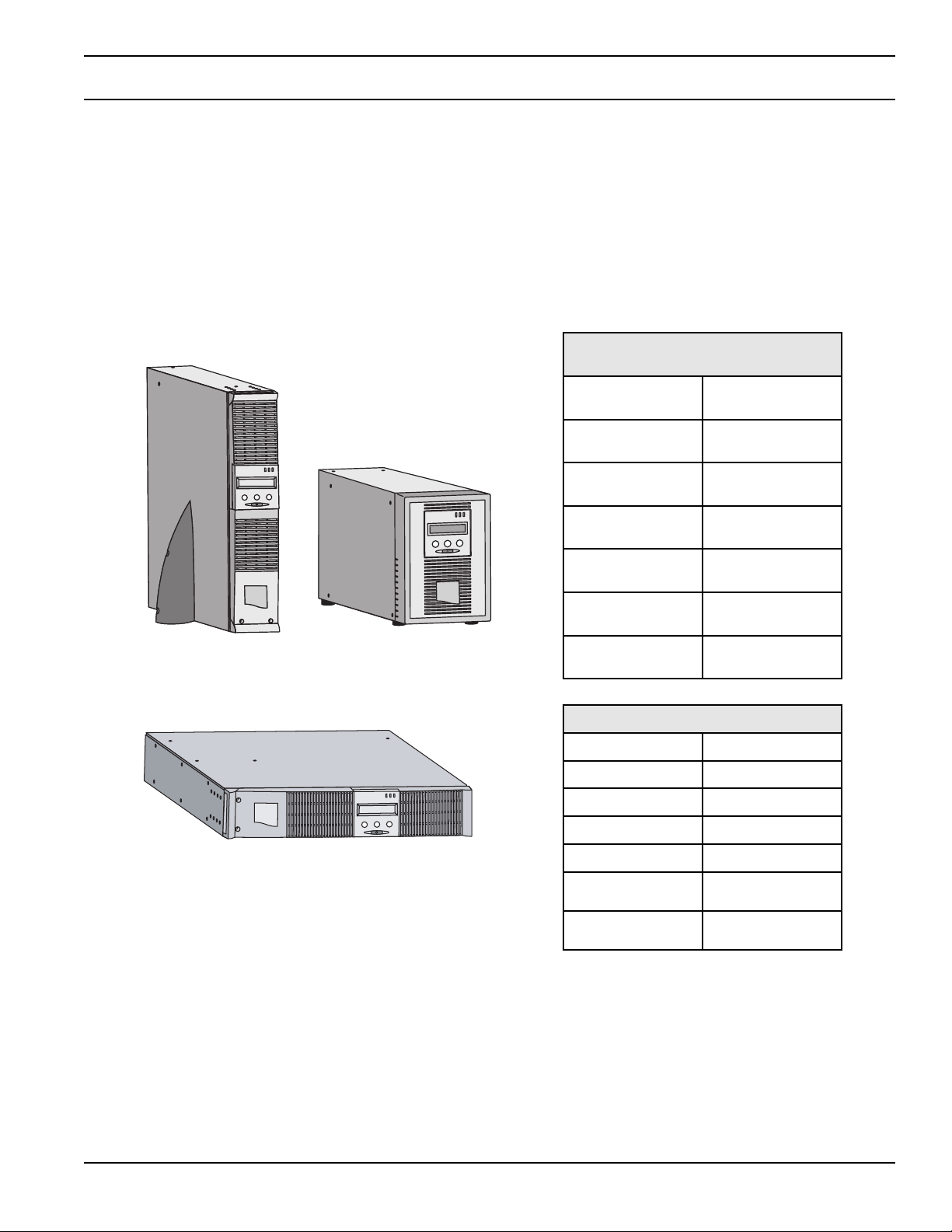
1.1 Standard Positions
Tower Position
Rack Position
Weights in kg / lbs
Pulsar 700 12.5 / 27.55
Pulsar 1000 15 / 33
Pulsar 1000 RT2U 18 / 39.68
Pulsar 1500 18 / 39.68
Pulsar 1500 RT2U 20.5 / 45.2
Pulsar EXB
1000/1500
21 / 46.3
Pulsar EXB
1000/1500 RT2U
24.5 / 54
Dimensions (H x W x D) in mm / inches
Pulsar 700
242 x 158 x 400 /
9.52 x 6.22 x 15.74
Pulsar 1000
242 x 158 x 400 /
9.52 x 6.22 x 15.74
Pulsar 1000 RT2U
438 x 86.5 x 480 /
17.24 x 3.4 x 18.9
Pulsar 1500
242 x 158 x 450 /
9.52 x 6.22 x 17.71
Pulsar 1500 RT2U
438 x 86.5 x 480 /
17.24 x 3.4 x 18.9
Pulsar EXB
1000/1500
242 x 158 x 400 /
9.52 x 6.22 x 15.74
Pulsar EXB
1000/1500 RT2U
440 x 86.5 x 480 /
17.32 x 3.4 x 18.9
ENGLISH
Contents
1 — 1
86-86700-00 A01
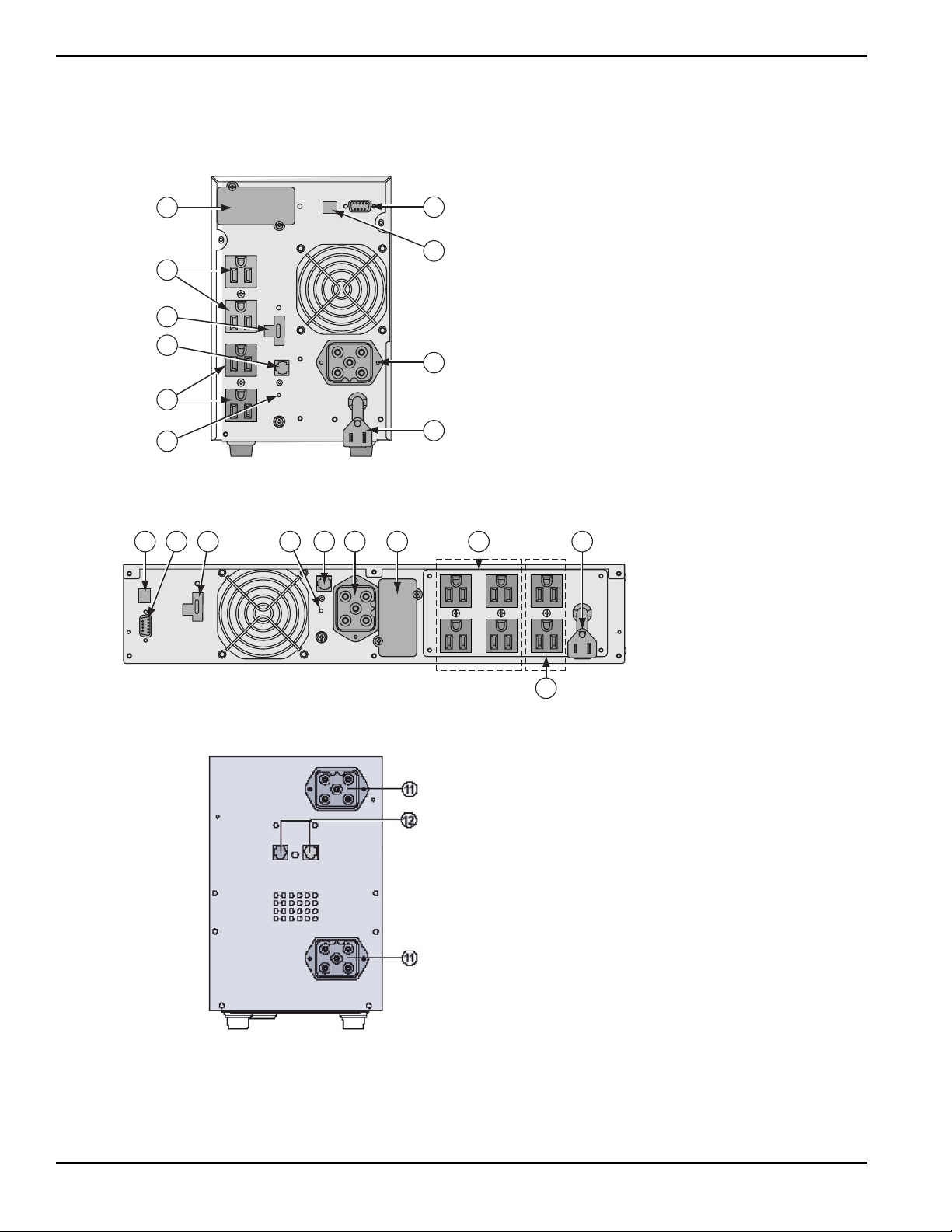
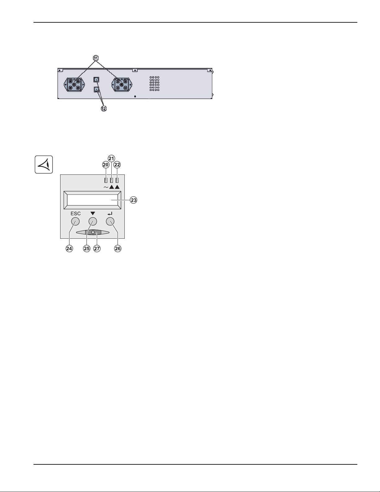
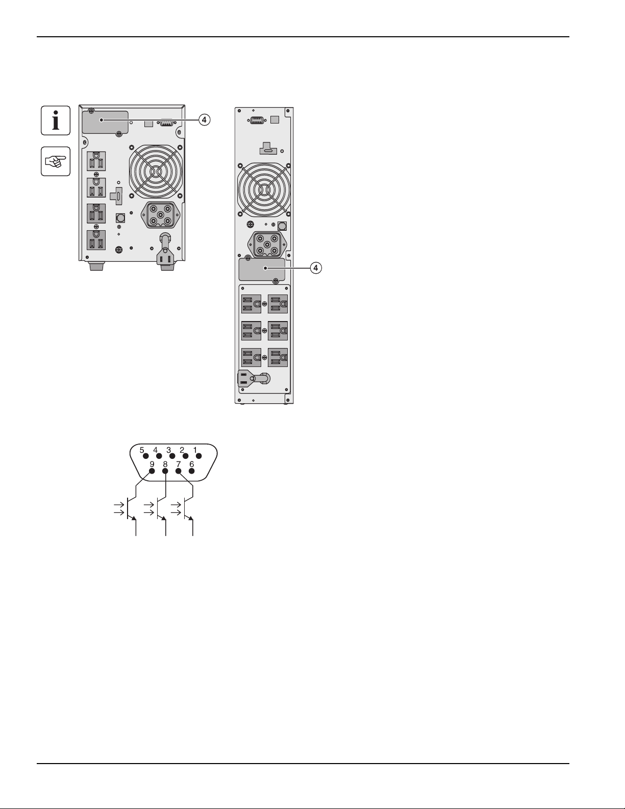
1.2 Rear Panels
Pulsar 700 / 1000 / 1500
Pulsar 1000 RT2U / 1500 RT2U
Pulsar EXB 1000/1500 (optional battery module)
(11) Connectors for battery modules (to the UPS or to
the other battery modules)
(12) Connectors for automatic recognition of battery
modules
1 2 5 310 6 4 8
7
9
(1) USB communication port
(2) RS232 and dry contacts communication port
(3) Connector for automatic recognition of a battery
EXB module (except on Pulsar 700)
(4) Slot for optional communication card
(5) Connector for remote ON/OFF and RPO (Remote
Power Off) control
(6) Connector for battery EXB module, except on
Pulsar 700
(7) Group of programmable outlets for connection of
equipment
(8) Group of outlets for connection of equipment
(9) Input power plug for connection to AC-power
source
(10) LED (SWF) indicating distribution system
phase/neutral reversal
5
8
4
6
1
2
9
3
7
10
Pulsar
Presentation
1 — 2
86-86700-00 A01
ENGLISH
Pulsar EXB 1000/1500 RT2U (optional battery module)
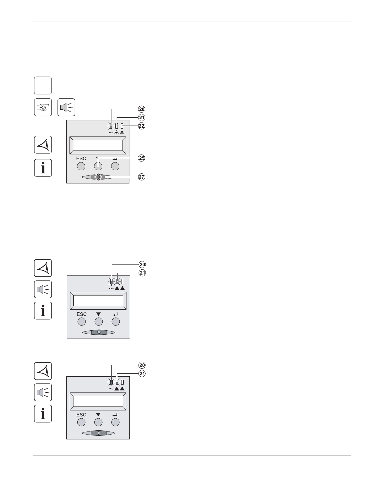
1.3 Control Panel
(20) Load protected LED
(21) Downgraded operation LED
(22) Load not protected LED
(23) Alphanumeric display
(24) Escape (cancel) button
(25) Scroll button
(26) Enter (confirm) button
(27) ON/OFF button for UPS and outlets
Installation and User Manual
Presentation
1 — 3
86-86700-00 A01
ENGLISH

(This page left blank intentionally)
Pulsar
1 — 4
86-86700-00 A01
ENGLISH
2 — 1
86-86700-00 A01
Installation
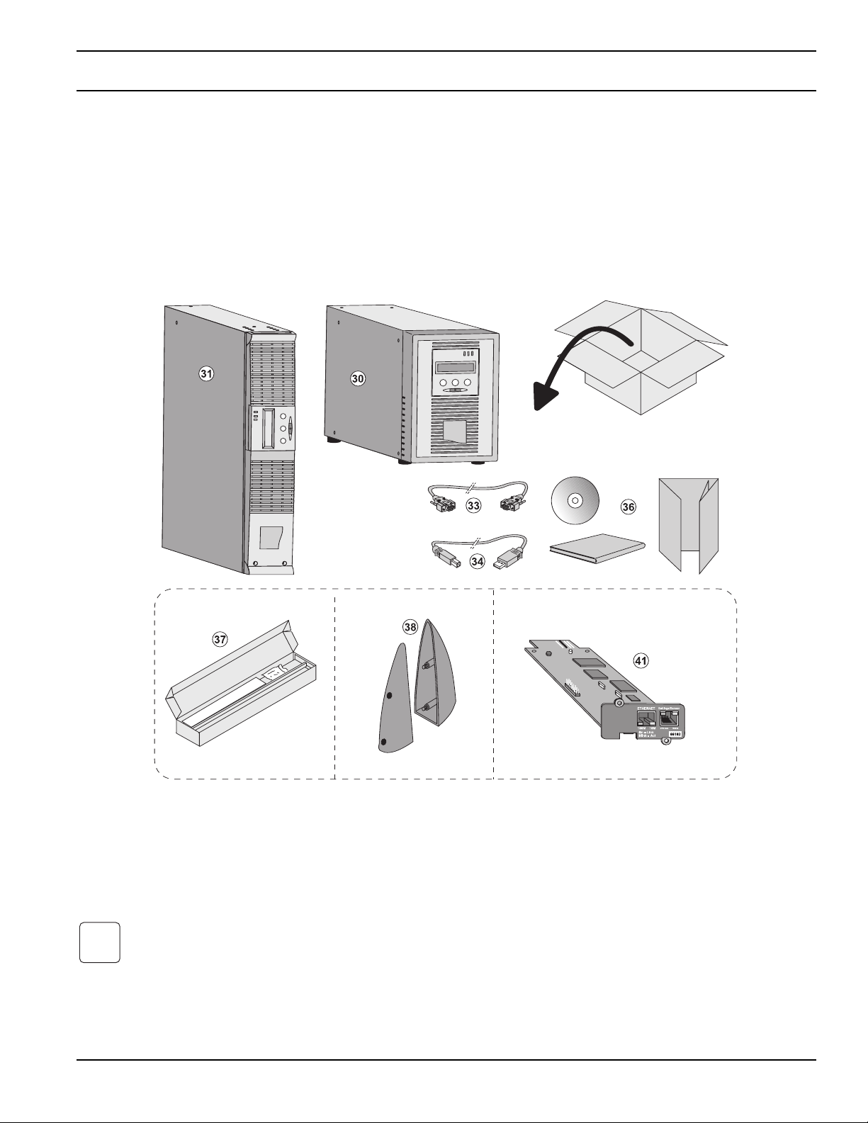
2.1 Unpacking and Contents Check
Packing materials must be disposed of in compliance with all local regulations concerning waste. Recycling symbols are
printed on the packing materials to facilitate sorting.
i
(37) Mounting kit for 19-inch bays
(38) 2 supports for the upright position (RT model only)
(41) NMC communication card (optional)
(30) Pulsar 700, 1000, 1500
(31) Pulsar 1000 RT2U, 1500 RT2U
(33) RS232 communication cable
(34) USB communication cable
(36) Solution-Pac CD-ROM and documentation Elements
supplied depending on the version or option
Installation
ENGLISH
Pulsar
Installation
2 — 2
86-86700-00 A01
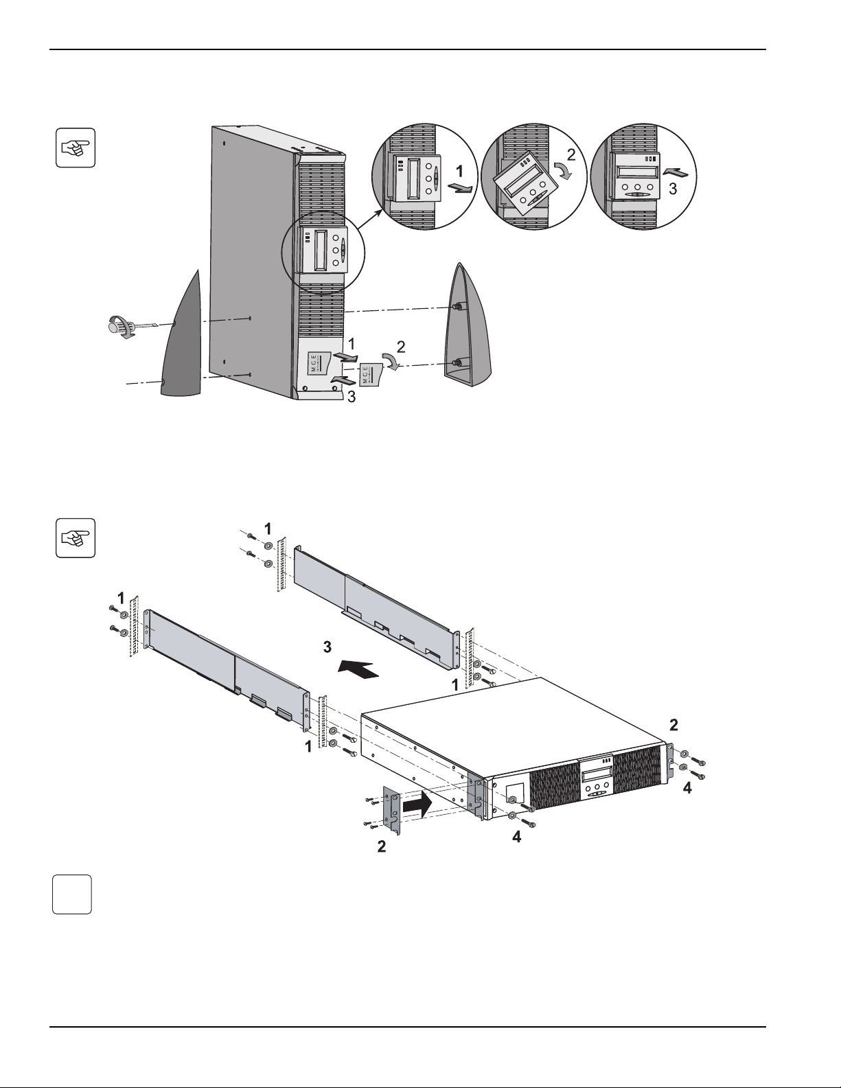
2.2 Installation of the RT Model in Tower Position
2.3 Installation of the RT Model in a Rack
It is advised to install the battery EXB module(s) at the lowest position in the rack, then install the UPS above.
Follow steps 1 to 4 for module mounting on the rails.
The rails and necessary hardware (37) are supplied by MGE Office Protection Systems.
i
ENGLISH
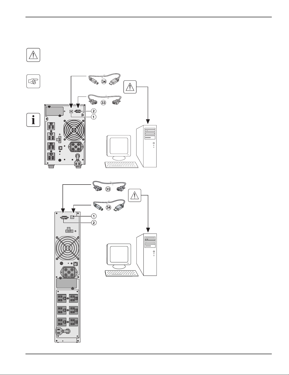
2.4 Communication Ports
Connection of RS232 or USB communication port (optional)
The RS232 and USB communication ports cannot operate simultaneously.
Tower model
RT model
1. Connect the RS232 (33) or USB (34) communica-
tion cable to the serial or USB port on the
computer equipment.
2. Connect the other end of the communication
cable (33) or (34) to the USB (1) or RS232 (2)
communication port on the UPS.
The UPS can now communicate with MGE Office
Protection Systems power management software.
Installation and User Manual
Installation
2 — 3
86-86700-00 A01
ENGLISH
Pulsar
Installation
2 — 4
86-86700-00 A01
Installation of optional communication cards (optional)
2.5 Connection to the Communication Port by Contact
When the status is active, the contact between the common (Pin 4) and the relevant information pin is closed.
Contact characteristics (optocoupler)
◗ Voltage: 48Vdc max
◗ Current: 25mA max per contact
◗ Power: 1.2W
◗ Pin 2, 3, 5 and 6: not used,
◗ Pin 1: operation on automatic by-pass,
◗ Pin 4: user common,
◗ Pin 7: low battery,
◗ Pin 8: load protected,
◗ Pin 9: operation on battery.
n.o.: contact normally open.
n.o. n.o. n.o.
It is not necessary to shutdown the UPS before
installing a communication card.
(4): Slot, with restricted access, for the communications-
card.
1. Remove the UPS cover (4) secured by screws.
2. Insert the communication card in the slot.
3. Put the UPS cover back in place using the
screws.
Tower model RT model
ENGLISH
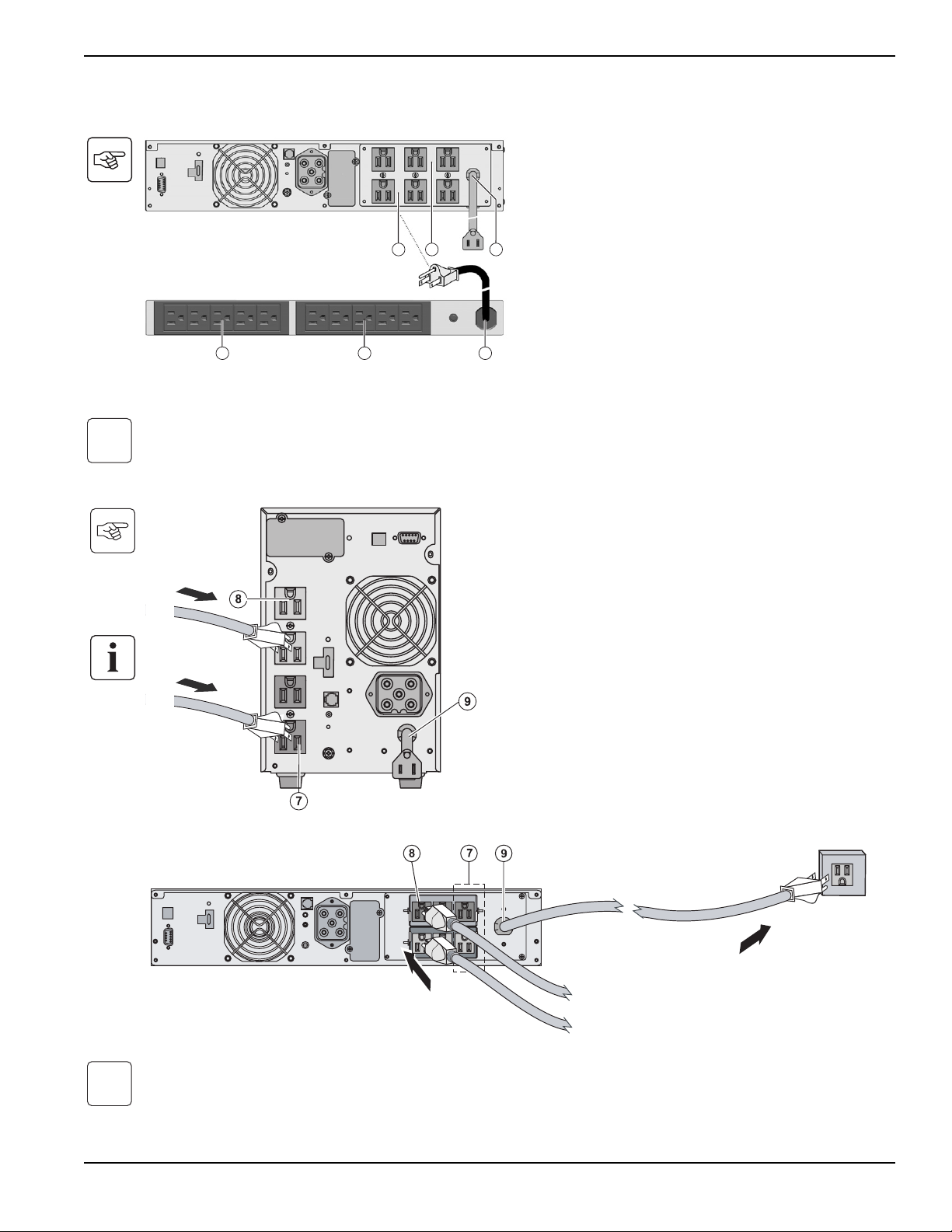
2.6 Connections with a FlexPDU (Power Distribution Unit) module (optional)
2.7 UPS Connection
Check that the indications on the name plate located on the back of the UPS correspond to the AC-power source and the
true electrical consumption of the total load.
Note. The UPS charges the battery as soon as it is connected to the AC-power source, even if button (27) is not pressed.
Once the UPS is connected to the AC-power source, eight hours of charging are required before the battery can supply
the rated backup time.
i
RT model
1. Connect the UPS socket (9) to the AC power
source using the power cable from the equip-
ments to be protected.
2. Connect the loads to the UPS.
It is preferable to connect the priority loads to the outlets
marked (8) and the non-priority loads to the outlets
marked (7) that can be programmed in pairs (1 and 2).
To program the outlets, the MGE Office Protection
Systems communications software is required.
Tower model
i
1. Connect the UPS socket (9) to the AC-power
source using the power cable from the equip-
ments to be protected.
2. Connect the input socket on the FlexPDU
module (48) to the UPS outlet (7) or (8). The
cable and the connectors are marked in red.
3. Connect the equipment to the outlets (45) and
(46) on the FlexPDU module. These outlets
differ, depending on the version of the FlexPDU
module.
4. Fit the connection securing system that prevents
the plugs from being pulled out accidentally.
7
45 46 48
8 9
Installation and User Manual
Installation
2 — 5
86-86700-00 A01
ENGLISH

Pulsar
2 — 6
86-86700-00 A01
(This page left blank intentionally)
ENGLISH
Operation
3.1 Start-Up and Normal Operation
For the initial start, AC power must be present to detect any wiring errors. Subsequently, the UPS can start even if AC
power is not present.
UPS personalization
If UPS personalization is desired, it is advised to enter the personalization mode at this time. This mode may be entered
using the buttons on the control panel or the Personal Solution-Pac software (Windows) included on the Solution-Pac CD-
ROM provided by MGE Office Protection Systems.
3.2 Operation on Battery Power
Transfer to battery power
◗ The connected devices continue to be supplied by
the UPS when AC power is no longer available.
The necessary energy is provided by the battery.
◗ LEDs (20) and (21) go ON.
◗ The audio alarm beeps every ten seconds.
The connected devices are supplied by the battery.
The display indicates the remaining backup time.
◗ LEDs (20) and (21) go ON.
◗ The audio alarm beeps every three seconds.
The remaining battery power is low. Shut down all
applications on the connected equipment because
automatic UPS shutdown is imminent.
Transfer to battery power
Low-battery warning
Press button (27) for approximately 1 second.
The connected devices are protected by the UPS.
◗ LED (20) is ON. If LED (22) is ON, a fault has
occurred (see the "Troubleshooting" section).
◗ During normal operation, the scroll button (25)
may be used to read UPS measurements (AC
input voltage, operating mode, battery capacity
and UPS serial number)
i
3 — 1
86-86700-00 A01 Operation
ENGLISH
Pulsar
3 — 2
86-86700-00 A01
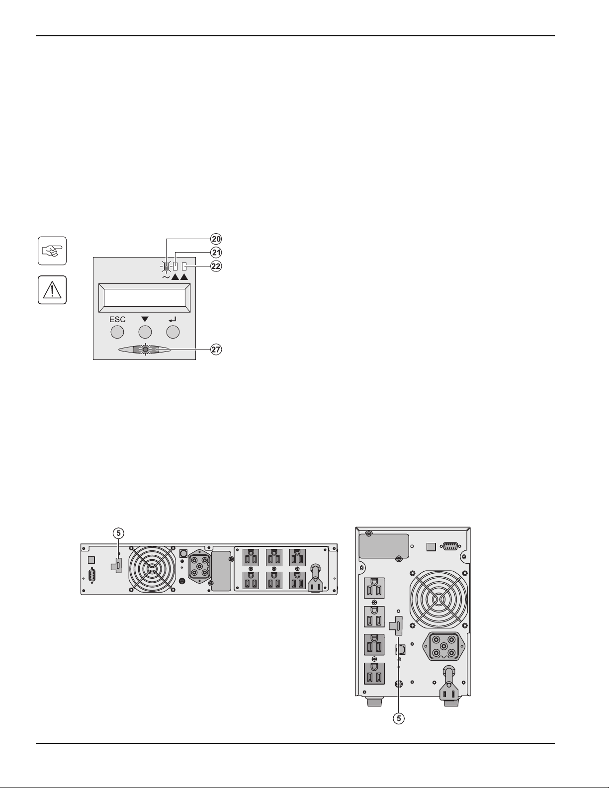
End of battery backup time
◗ All the LEDs go OFF.
◗ The audio alarms stops.
The UPS is completely shut down.
3.3 Return of AC Power
Following an outage, the UPS restarts automatically when AC power returns (unless the restart function was disabled via
UPS personalization) and the load is again supplied.
3.4 UPS Shutdown
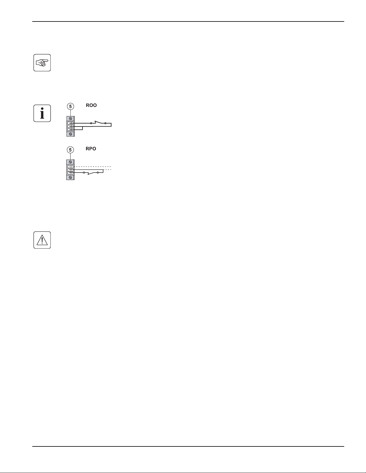
3.5 Using the UPS Remote Control Functions
Pulsar has the choice of two remote control options.
◗ RPO: Remote Power Off allows a remote contact to be used to disconnect all the equipment connected to the
UPS from the power supply. Restarting the UPS requires manual intervention.
◗ ROO: Remote ON/OFF allows remote action of button (27). These functions are obtained by opening a contact
connected between the appropriate pins of connector (5) on the rear panel of the UPS (see diagram on follow-
ing page).
RT m odel
Tower m od el
Press button (27) for approximately 1 second.
The devices connected to the UPS are no longer
supplied.
Operation
ENGLISH
Remote control connection and test
1. Check the UPS is shut down and the electrical supply network disconnected.
2. Remove connector (5) by unfitting the screws.
3. Connect a normally closed volt-free contact (60 Vdc / 30 Vac max, 20 mA max, 0.75mm 2 cable cross section)
between the two pins of connector (5), see diagram.
4. Plug connector (5) into the back of the UPS.
5. Connect and restart the UPS according to the previously described procedures.
6. Activate the external remote shut down contact to test the function.
Warning: This connector must only be connected to SELV (Safety Extra Low Voltage) circuits.
Contact open: shut down of UPS
Contact closed: start-up of UPS (UPS connected to the
network and network energized)
Note: local On/Off control via button (27) has priority over
the remote control order.
Contact open: shut down of UPS
To return to normal operation, deactivate the external
remote shut down contact and restart the UPS using
button (27).
Installation and User Manual
Operation
3 — 3
86-86700-00 A01
ENGLISH

(This page left blank intentionally)
Pulsar
3 — 4
86-86700-00 A01
ENGLISH
Access to Maintenance and Personalization Data
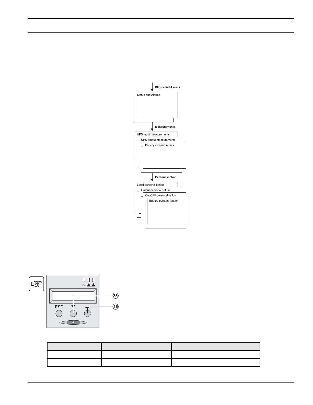
4.1 Display Menus Arrangement
4.2 Access to Measurements
Press the scroll button (25) to access any status conditions and alarms, then the measurements for voltage, current,
frequency, power output and battery backup time.
4.3 Personalization Using the Control Panel
Local personalization
Function Factory setting Other available settings
Language English French, Spanish, Portuguese
Audio alarm Enabled Disabled
◗ Press the scroll button (25) several times until the
personalization menu is reached.
◗ Press the Enter button (26) to access the different
possibilities.
◗ Finally, confirm the selection by pressing the Enter
button (26) again.
Contents
4 — 1
86-86700-00 A01
ENGLISH
Output personalization
(1) These parameters may be modified only when the UPS is OFF. Detailed comments are available in the Personal
Solution-Pac software.
ON/OFF personalization
Battery personalization
4.4 Personalization using external software
◗ Insert the Solution-Pac CD-ROM in the drive.
◗ On the first navigation screen, select "Point to Point solution" and follow the instructions on how to install the
Personal Solution-Pac software.
◗ Then select "Settings", "Advanced settings" and "UPS settings". Note that the Linux/Unix/MacOS versions of the
Personal Solution-Pac software do not offer this possibility.
Function Factory Setting
Other available
settings
Comments
Battery test Weekly test
No test / daily test /
monthly test
Low-battery warning 20% 0 to 100% Adjustable in 1% steps.
Selection of the
backup time
Automatic detection
of number of battery
modules
13 to 200 Ah
Battery protection
against excessive
discharges
Enabled Disabled
Excessive discharges when function
disabled, MGE Office Protection Systems
warranty no longer applies.
Function Factory Setting
Other available
settings
Comments
Start on battery power Enabled Disabled
Automatic restart Enabled Disabled
The UPS restarts automatically when AC
power returns.
Energy savings Disabled Enabled
When function enabled, battery shuts down
when power drops to <5%.
Detection of phase/
neutral inversion
(SWF)
Enabled Disabled
Neutral inversion (SWF) When function
enabled, the UPS remains OFF if the
system detects phase/neutral inversion.
Function Factory Setting
Other available
settings
Comments
Output voltage
(1)
120 Volts AC 100 to 127 Volts AC
Frequency
converter
(1)
Disabled Enabled
The connected devices are never trans-
ferred to the bypass.
Output frequency
(1)
Automatic selection 50 or 60 Hz
User selectable only if the frequency-
converter function is enabled.
Transfer to the
bypass AC input
(1)
Bypass AC power
must be within
tolerances
Bypass AC power
may be outside
tolerances
Overload level
(1)
100% 30 / 50 / 70% Alarm if threshold is overrun.
Pulsar
Access to Maintenance and Personalization Data
4 — 2
86-86700-00 A01
ENGLISH

Troubleshooting
5.1 Troubleshooting
If LED (21) or (22) is ON, a fault or an alarm has occurred. Use the escape button (24) to stop the audio alarm.
Display Description Corrective Action
1
The UPS does not start, the
alphanumeric display indicates:
COLD START NOK CHECK AC
WIRING
The AC input power is not con-
nected or is connected to the
UPS output.
Check the UPS is correctly connected
to the AC input power.
2
LED (22) is ON, the SWF LED
(11) at the rear of the UPS is ON.
The alphanumeric display indi-
cates: SITE WIR. FAULT CHECK
AC WIRING
Phase inversion on AC input
power. The UPS does not start.
◗ In an earthed-neutreal system, to
correct the wiring, call an electrician to
modify the connections.
◗ For all other types of system, disable
the detection function.
3
LED (22) is ON, the alphanumeric
display indicates: NO BATTERY
CHECK CONNECTION
The battery is incorrectly
connected.
Check battery connections (see
Section 5.2, Battery-Module
Replacement).
4
LED (22) is ON, the alphanumeric
display indicates: BATTERY
FAULT SERV REQUIRED
A fault is detected on the battery. Replace the battery (see Section 5.2,
Battery-Module Replacement). Call the
after-sales support
5
LED (21) is ON, the alphanumeric
display indicates: OVERLOAD
ALARM REDUCE LOAD
The load level exceeds the pro-
grammed overload level or UPS
capacity.
Check the power drawn by the con-
nected devices and disconnect any
non-priority devices. Check the pro-
grammed overload level.
6
LED (22) is ON, the alphanumeric
display indicates: LOAD UNPRO-
TECTED OUTPUT OVERLOAD
The UPS is overloaded. Devices
connected to the UPS are fed
directly by the electrical network
via the By-pass.
Check the power drawn by the con-
nected devices and disconnect any
non-priority devices.
7
LED (22) is ON, the alphanumeric
display indicates: REDUCE
LOAD RESTART UPS
After repetitive overloads, the
UPS is locked in the By-pass
position. Devices connected to
the UPS are fed directly by the
electrical network.
Check the power drawn by the con-
nected devices and disconnect any
non-priority devices. Shut down and
restart the UPS to return to normal
operation.
8
LED (22) is ON, the alphanumeric
display indicates: OVERLOAD
FAULT REDUCE LOAD
The UPS shut down automatically
because of overload at the UPS
output.
Check the power drawn by the con-
nected devices and disconnect any
non-priority devices.
9
LED (22) is ON, the alphanumeric
display indicates: LOAD SHORT-
CIRCU CHECK WIRING
The UPS shut down automatically
because of a short-circuit at the
UPS output.
Check the installation at the UPS out-
put (wiring, fault equipment).
10
LED (22) is ON, the alphanumeric
display indicates: INTERNAL
FAULT SERV REQUIRED
A UPS internal fault has occurred.
There are two possible situations:
◗ The load is still supplied, but
directly with AC power via the
bypass,
◗ The load is no longer supplied.
Call the after-sales support depart-
ment.
11
The alphanumeric display indi-
cates: REMOTE POWER OFF
RPO
Switching of the Remote Power
Off (RPO) has led to the shut
down of the UPS.
Replace the contact in the normal
position, and press the ON/OFF button
to restart.
ENGLISH
Troubleshooting
5 — 1
86-86700-00 A01
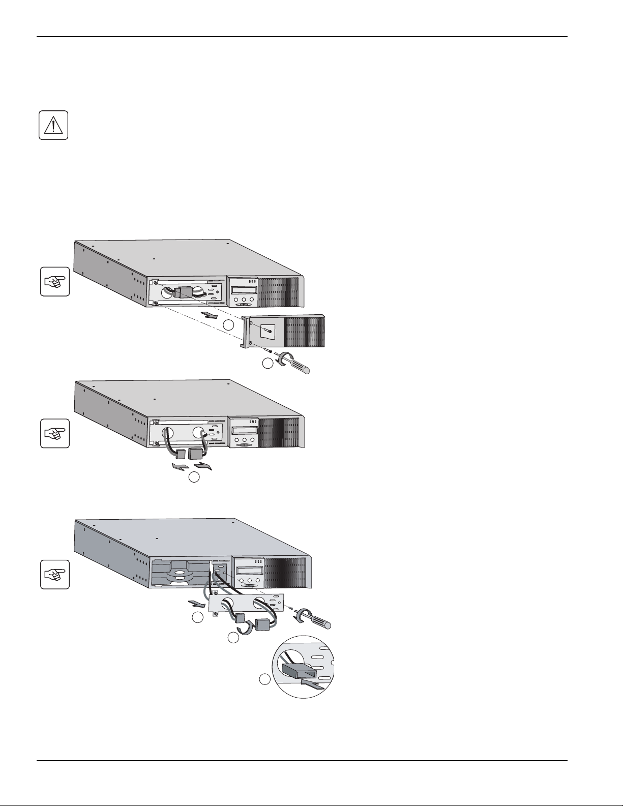
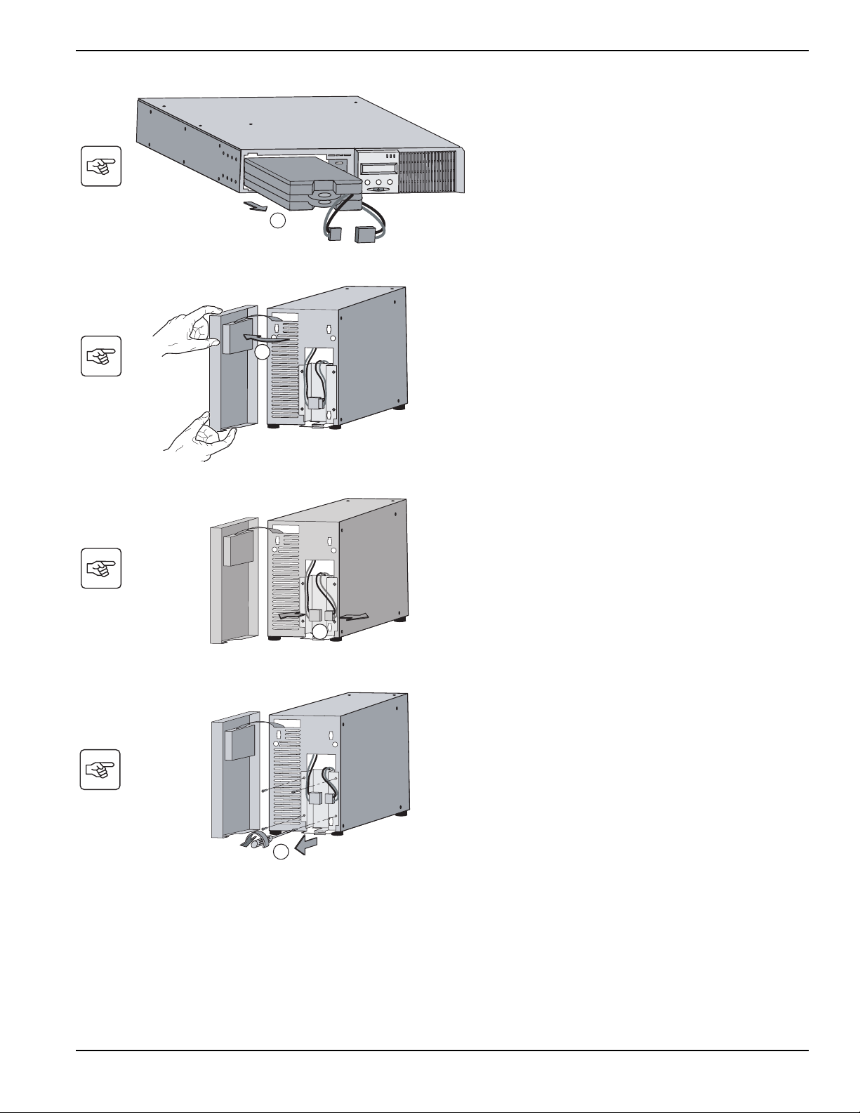
5.2 Battery-Module Replacement
Safety recommendations
The battery can cause electrocution and high short-circuit currents. The following safety cautions are required
before servicing the battery components:
◗ Remove watches, rings, bracelets and all other metal objects from the hands and arms.
◗ Use tools with an insulated handle.
Battery-module removal
D Remove the metal protection cover in front of the
battery (two screws).
E Turn the connector.
F Pass the connector through the hole.
F
E
D
A Unscrew the left-hand side of the front panel (two
screws).
B Remove the part.
C Disconnect the battery block by separating the
two connectors (never pull on the wires).
R
RT m odel
B
A
C
Pulsar
Troubleshooting
5 — 2
86-86700-00 A01
ENGLISH
C Remove the 4 fixing screws on the metal
protection cover of the battery.
C
B Disconnect the battery block by separating the
two connectors (never pull on the wires).
B
A Put the front panel near the UPS.
T
Tower m od el
A
G Pull the plastic tab to remove the battery block
and replace it.
G
Installation and User Manual
Troubleshooting
5 — 3
86-86700-00 A01
ENGLISH
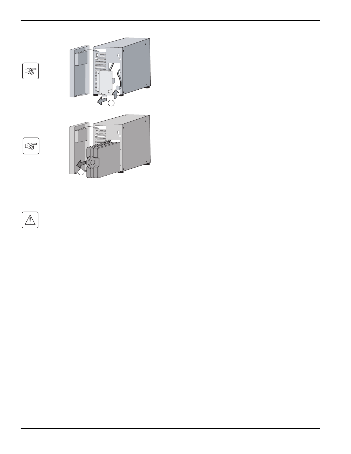
Mounting the new battery module
Carry out the above instructions in reverse order.
◗ To ensure safety and high performance, use only batteries supplied by MGE Office Protection Systems.
◗ Take care to firmly press together the two parts of the connector during remounting.
E Pull the plastic tab to remove the battery block
and replace it.
E
D Remove the metal protection cover of the
battery.
D
Pulsar
Troubleshooting
5 — 4
86-86700-00 A01
ENGLISH
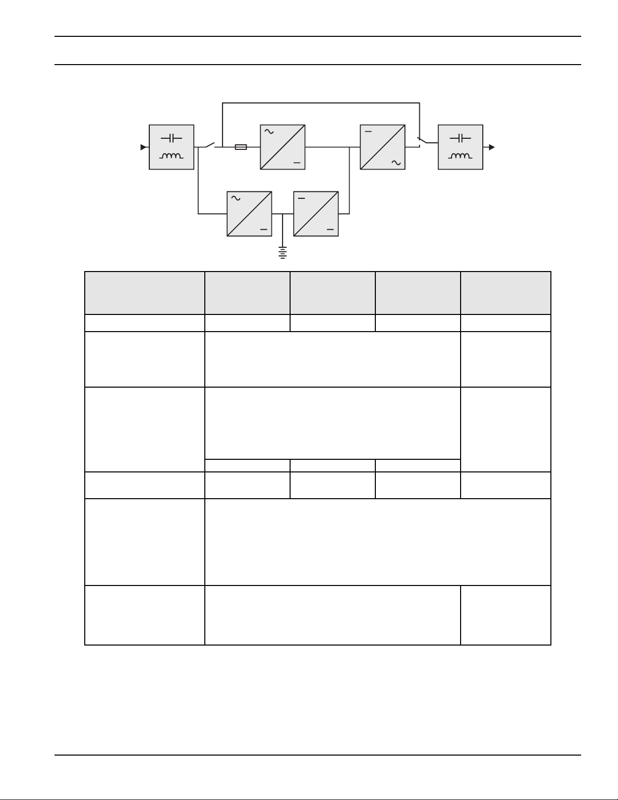
Appendix
Technical Specifications
(1) EXB Module for Pulsar 1000 and Pulsar 1500
(2) EXB RT2U Module for Pulsar 1000 RT2U and Pulsar 1500 RT2U.
(3) 900W, in standard configuration, 800W with at least 1 EXB connected
(4) 1290W in standard configuration, 1200W with at least 1 EXB connected
(5) Values for 33% / 66% / 100% of nominal power rating
(6) Adjustable from 100V to 127V using the UPS Config software
(7) Frequency-converter mode is programmable using the UPS Config software
(8) Nominal, for 120V output voltage
Pulsar 700
Pulsar 1000
Pulsar 1000 RT2U
Pulsar 1500
Pulsar 1500 RT2U
Pulsar EXB
1000/1500 (1)
Pulsar EXB
1000/1500 RT2U (2)
Output power 700VA / 630W 1000VA /900 W
(3)
1500VA /1290 W
(4)
AC input power
◗ Voltage
◗ Frequency
◗ Power factor
Single phase 60 / 70 / 80V to 142V (5)
50/60 Hz autoselect
> 0.95
Load output
◗ Voltage
◗ Frequency
◗ Harmonic distortion
◗ Overload capacity
◗ Current
Single phase 120V ±3% (6)
50/60 Hz ±0.5% (7)
< 4% for linear load, < 6% for nonlinear load
102% continuous, 130% 12s, > 130% 2s
5.8A
(8)
8.3A
(8)
12.5A
(8)
Battery, sealed lead acid,
maintenance free
2x12V – 7Ah 3x12V – 7Ah 3x12V – 9Ah
Two string of
3x12V -9Ah
Environment
◗ Operating temperature range
◗ Relative humidity
◗ Leakage current
◗ Storage temperature range
◗ Altitude
0°C to 40°C
20% to 90% (without condensation)
< 1.1mA
-25°C to 40°C
1000 m
Standards and certification
◗ Safety
◗ EMC
◗ Surge suppressor
UL 1778 (4th edition), CSA C22.2 No 107.3-05
FCC Subpart B, class A
IEEE/ANSI 62.41
Appendix
A — 1
86-86700-00 A01
ENGLISH
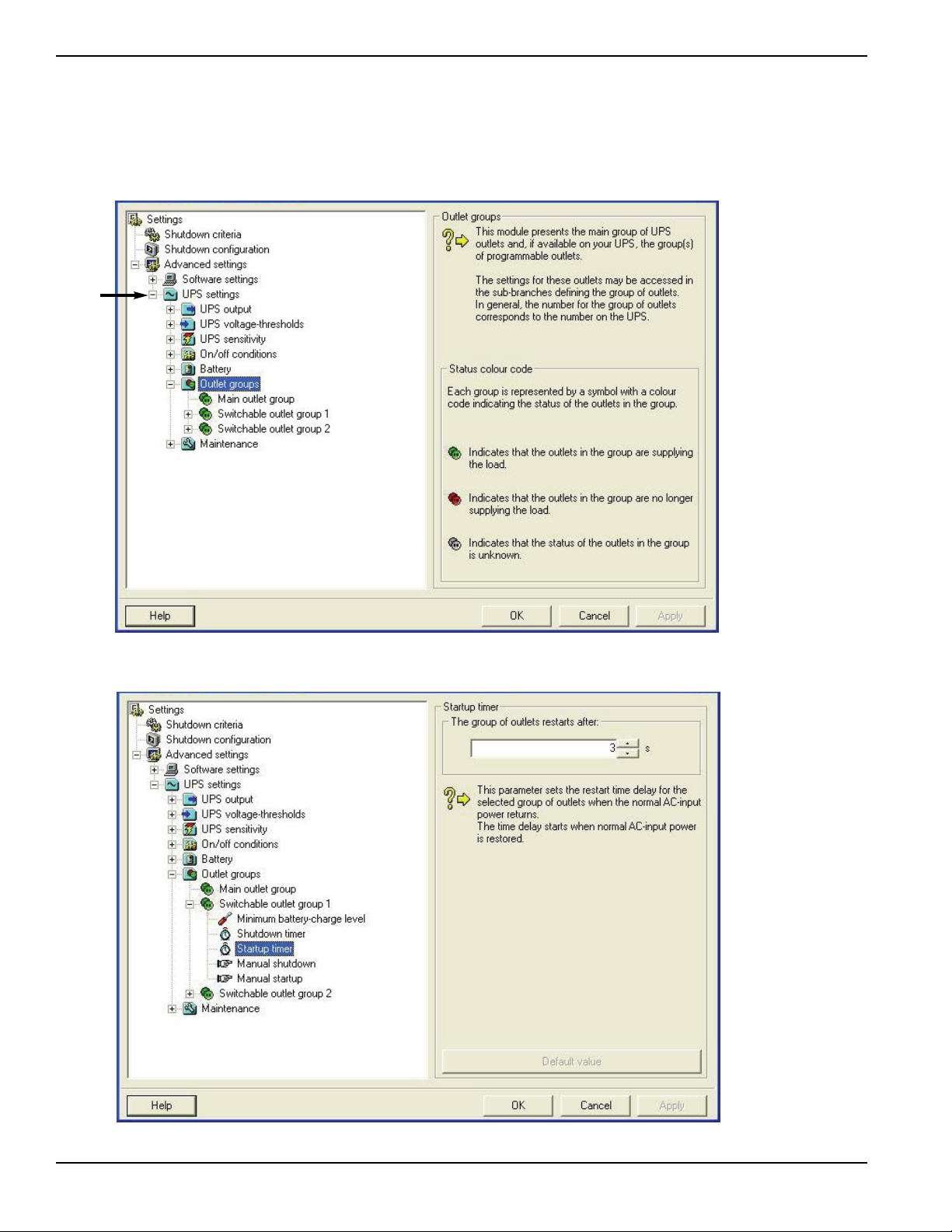
6.2 Programming the Programmable Outlets
1. To open the Setting window, left-click on Start Menu / Programs / MGE UPS Systems / Personal Solution Pac /
Settings, or right-click on the PSP power plug located in the SYS Tray.
2. Click on the “+” symbol next to “UPS Settings” to expand the “UPS Settings” section.
3. Click on “Startup Timer” and change the “The group of outlets restarts after” to “0” to have powershare outlet provide
power at the same time the as main outlets.
Pulsar
Appendix
A — 2
86-86700-00 A01
 Loading...