


MGE UPS Systems 1500 Rack, 1100 Rack, PULSAR 1500, 800 Rack, 500 Rack User Manual
...www.mgeups.com |
MGE UPS SYSTEMS |
Pulsar Evolution
1500 /1500 Rack
1100 /1100 Rack
800 /800 Rack
500 Rack
Installation and user manual
English
Français
Deutsch
Italiano
Español
Nederlands
O
Y
P
O
T
S
L
L
I
W
G
N
I
H
T
O
N
N
U
O
W
3400711700/AB
www.mgeups.com |
MGE UPS SYSTEMS |
|
|
Pulsar Evolution
1500 /1500 Rack
1100 /1100 Rack
800 /800 Rack
500 Rack
Installation and user manual
O
Y
P
O
T
S
L
L
I
W
G
N
I
H
T
O
N
N
U
O
W
34007117EN/AB - Page 1

Page 2 - 34007117EN/AB

Introduction
Thank you for selecting an MGE UPS SYSTEMS product to protect your electrical equipment.
The Pulsar Evolution range has been designed with the utmost care. We recommend that you take the time to read this manual to take full advantage of the many features of your UPS.
MGE UPS SYSTEMS pays great attention to the environmental impact of its products. Measures that have made Pulsar Evolution a reference in environmental protection include:
the eco-design approach used in product development,
recycling of Pulsar Evolution at the end of its service life.
To discover the entire range of MGE UPS SYSTEMS products and the options available for the Pulsar Evolution range, we invite you to visit our web site at www.mgeups.com or contact your MGE UPS SYSTEMS representative.
Important: before installing and using the UPS, always read the safety instructions (document n° 3400722200).
34007117EN/AB - Page 3
Foreword
Using this document
Information may be found in two ways, using:
the contents;
the index.
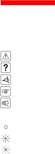
Pictograms
Important instructions that must always be followed.
Information, advice, help.
Visual indication.
Action.
Audio indication.
In the illustrations on the following pages, the symbols below are used:
LED off.
LED on.
LED flashing.
Page 4 - 34007117EN/AB

Contents
1.Presentation
1.1 |
Overall view ................................................................................................................................. |
7 |
|
Tower models .................................................................................................................................. |
7 |
|
Rack models ................................................................................................................................... |
7 |
1.2 |
Back ............................................................................................................................................. |
8 |
1.3 |
Control panel ................................................................................................................................. |
9 |
2.Installation
2.1 |
Unpacking and parts check ....................................................................................................... |
10 |
|
Tower models ................................................................................................................................ |
10 |
|
Rack models ................................................................................................................................. |
11 |
2.2 |
Installation ................................................................................................................................... |
12 |
|
Tower models ................................................................................................................................ |
12 |
|
800/1100/1500 Rack models ........................................................................................................ |
13 |
|
500 Rack model ............................................................................................................................ |
14 |
2.3 |
Connecting the protected equipment ....................................................................................... |
15 |
2.4 |
Connection to the RS232 or USB communications port (optional) ......................................... |
16 |
2.5 |
Connection to the data-line protection port (optional) ............................................................. |
16 |
2.6 |
Installation of the communications-card option ...................................................................... |
17 |
3.Operation
3.1 |
Start-up ........................................................................................................................................ |
18 |
3.2 |
Shift to booster or fader mode (during voltage variations in the AC-input power) ..................... |
18 |
3.3 |
Operation on battery power (following failure of AC-input power) ............................................. |
19 |
|
Transfer to battery power .............................................................................................................. |
19 |
|
Threshold for the low-battery warning ........................................................................................... |
19 |
3.4 |
Personalisation (optional) ........................................................................................................... |
20 |
|
Function ........................................................................................................................................ |
20 |
|
ON / OFF conditions tab ............................................................................................................... |
20 |
|
Battery tab ..................................................................................................................................... |
20 |
|
Voltage-thresholds tab .................................................................................................................. |
21 |
|
Sensitivity tab ................................................................................................................................ |
21 |
34007117EN/AB - Page 5

Contents
4.Maintenance
4.1 |
Trouble-shooting......................................................................................................................... |
22 |
4.2 |
Replacement of the battery module .......................................................................................... |
23 |
|
Tower models ................................................................................................................................ |
23 |
|
Rack models ................................................................................................................................. |
25 |
5. Environment ..................................................................................................................................... |
27 |
|
6.Appendices
6.1 |
Technical data ............................................................................................................................. |
28 |
|
Simplified diagram ........................................................................................................................ |
26 |
|
Technical characteristics ............................................................................................................... |
29 |
|
Examples of battery backup times ................................................................................................ |
30 |
6.2 |
Glossary....................................................................................................................................... |
31 |
6.3 |
Index............................................................................................................................................. |
32 |
Page 6 - 34007117EN/AB
1. Presentation
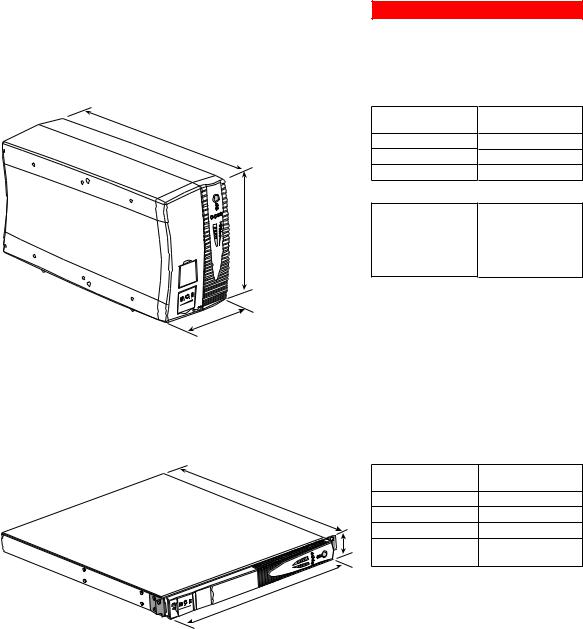
1.1 Overall view
Tower models
|
Dimensions in mm |
D |
(W x H x D) |
|
|
Evolution 800 |
150 x 237 x 415 |
Evolution 1100 |
150 x 237 x 415 |
Evolution 1500 |
150 x 237 x 483 |
Weight in kg
|
U |
L S |
A R |
P |
|
||
Evolution0 |
|||
1 1 |
0 |
|
|
H |
Evolution 800 |
10.5 |
|
Evolution 1100 |
11.5 |
|
Evolution 1500 |
15 |
W
Rack models
L S |
A R |
P U |
|
EvolutionRack |
|
1500 |
|
|
|
Dimensions in mm |
|
D |
|
(W x H x D) |
|
Evolution 500 Rack |
438 x 43.5 x 353 |
||
|
|||
|
Evolution 800 Rack |
438 x 43.5 x 499 |
|
|
Evolution 1100 Rack |
438 x 43.5 x 499 |
|
H |
Evolution 1500 Rack |
438 x 43.5 x 522 |
|
|
|||
|
|
(19") (1U) |
W |
|
Weight in kg |
|
|
|
|
Evolution 500 Rack |
9 |
|
Evolution 800 Rack |
15.5 |
|
|
|
|
Evolution 1100 Rack |
16 |
|
Evolution 1500 Rack |
19 |
34007117EN/AB - Page 7
1. Presentation
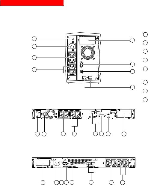
1.2 Back
Pulsar Evolution 800 / 1100 / 1500
Pulsar Evolution 1500: |
1 |
USB communications port. |
|
7 |
4 |
|
|
|
RS232 communications port. |
||
|
2 |
||
8 |
|
|
|
|
3 Data-line protection. |
||
5 |
4 Slot for communications-card option. |
||
|
|||
2 |
2 |
|
|
5 |
Outlets for direct connection of |
||
6 |
|||
1 |
1 |
protected equipment. |
|
|
|||
|
|
||
|
6 Programmable outlets (1 and 2). |
||
|
3 |
|
|
|
7 Input circuit-breaker. |
||
Pulsar Evolution 500 / 800 / 1100 Rack |
8 Socket for connection to AC-power |
||
|
source. |
||
|
|
||
1 2
8 |
7 |
5 |
6 |
3 |
2 |
1 |
4 |
Pulsar Evolution 1500 Rack
1 2
4 |
8 |
7 |
2 |
1 |
3 |
5 |
6 |
Page 8 - 34007117EN/AB
1. Presentation
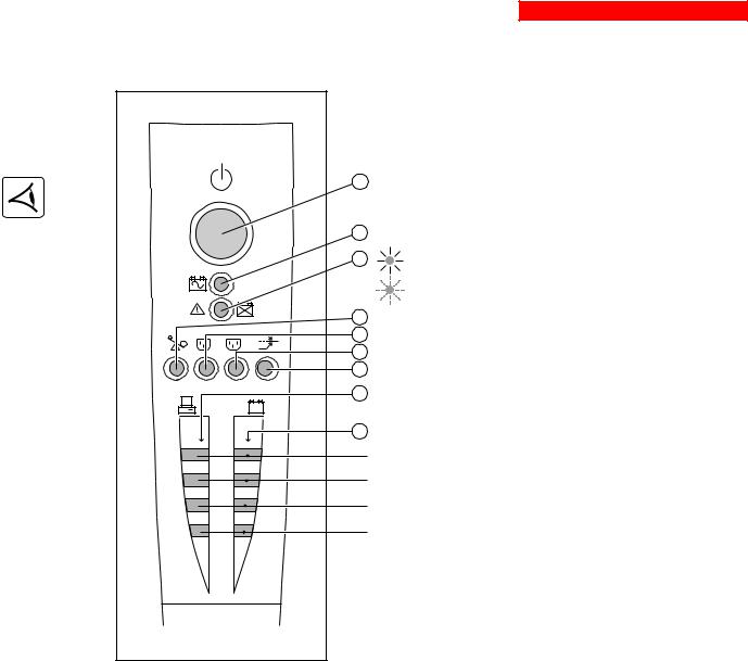
1.3 Control panel
|
10 |
Iluminated ON/OFF button for the outlets. |
|
11 |
Operation on battery power. |
|
12 |
UPS fault. |
|
|
Battery fault. |
|
13 |
Overload. |
1 |
14 |
Group 1 programmable outlets supplied with power. |
2 |
Group 2 programmable outlets supplied with power. |
|
|
15 |
|
|
16 |
Booster or fader mode. |
% |
17 |
Bargraph indicating percent load at output. |
% |
|
|
|
|
|
|
18 |
Bargraph indicating the battery charge level. |
|
|
76 to 100%. |
|
|
51 to 75%. |
|
|
26 to 50%. |
|
|
0 to 25%. |
|
|
34007117EN/AB - Page 9 |
2. Installation
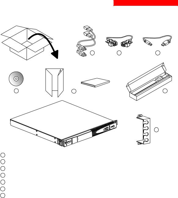
2.1 Unpacking and parts check
Tower models
20 |
21 |
22 |
23 |
24 |
|
U |
L S |
A R |
P |
|
|
|
Evolution0 |
|||
1 1 |
0 |
|
|
20Two cords for connection of the protected equipment.
21RS232 communications cable.
22USB communications cable.
23CD-ROM with the Solution-Pac and UPS Driver software.
24Product documentation.
Page 10 - 34007117EN/AB
2. Installation
Rack models
20 |
21 |
22 |
23 |
24 |
25 |
26
L S |
A R |
P U |
|
EvolutionRack |
|
1500 |
|
20Two cords for connection of the protected equipment.
21RS232 communications cable.
22USB communications cable.
23CD-ROM with the Solution-Pac and UPS Driver software.
24Product documentation.
25Telescopic rails for mounting in 19" bay with mounting hardware.
26Securing system for equipment power cords.
34007117EN/AB - Page 11
2. Installation
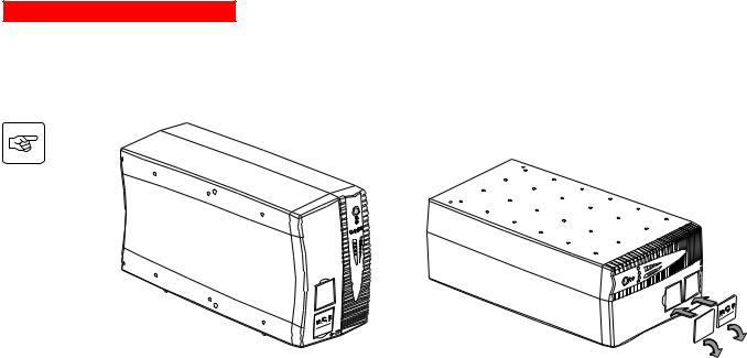
2.2 Installation
Tower models
|
U |
L S |
A R |
P |
|
||
Evolution0 |
|||
1 1 |
0 |
|
|
|
|
|
S |
A |
R |
|
|
L |
|
||
|
|
|
|
||
Evolution0 |
|||||
P |
U |
|
0 |
|
|
1 |
1 |
|
|
|
|
Page 12 - 34007117EN/AB
2. Installation
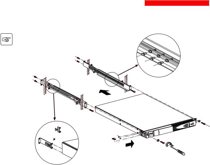
800/1100/1500 Rack models
Follow steps 1 to 6 for rack mounting of the UPS on the rails.
2 |
1 |
|
|
|
6 |
2 |
|
|
2 |
|
4 |
6 
2
P U L |
S A R |
Evolution |
|
1500 |
Rack |


 5 3
5 3
3
5
The rails and the necessary mounting hardware are supplied by MGE UPS SYSTEMS.
34007117EN/AB - Page 13

2. Installation
500 Rack model
2
P U L |
S A R |
Evolution |
|
1500 |
Rack |
1
3
1
3
|
L |
S |
A R |
EvolutionRack |
|||
P U |
|
|
|
1500 |
|
|
|
|
L |
S |
A R |
EvolutionRack |
|||
P U |
|
|
|
1500 |
|
|
|
Page 14 - 34007117EN/AB
2. Installation
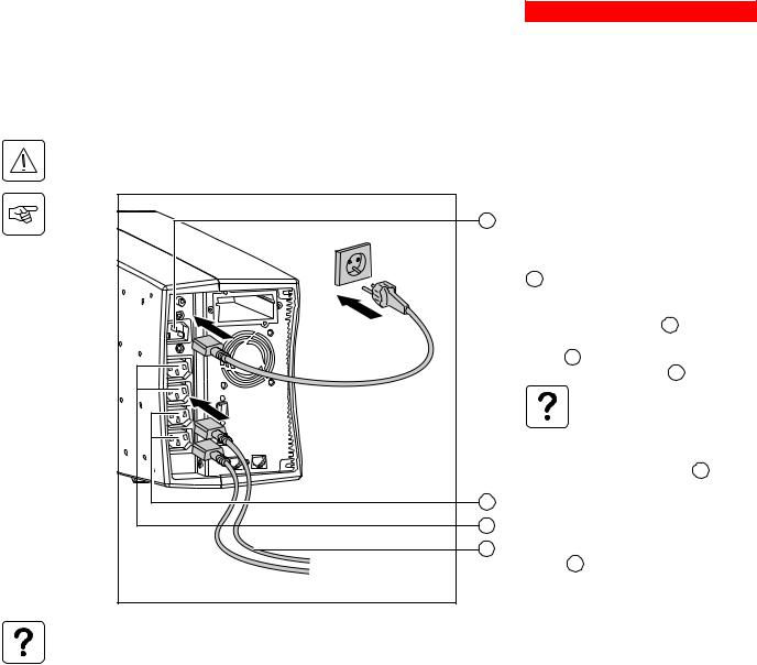
2.3 Connecting the protected equipment
A Pulsar Evolution 1500 tower UPS has been used below to illustrate the instructions. The principle is the same for all the other tower and rack models.
Check that the indications on the rating plate on the back of the UPS correspond to your AC-power system and to the actual electrical consumption of all the equipment to be connected to the UPS.
8 |
2 |
1 |
6 |
5 |
20 |
1 - Remove the power cord supplying the equipment to be protected.
2 - Connect the power cord (1) just removed from the equipment to the AC-power socket 8 , and then to the AC-power wall outlet.
3 - Connect the protected equipment to the UPS using the two cords 20 .
Connect priority loads to the two standard outlets 5 and any non-priority loads to the
two programmable outlets |
6 (1 and 2). |
If the UPS is connected to a computer running MGE communications software, it is possible to program the interruption of power to the programmable outlets 6 during operation on battery power, thus reserving backup power for the priority loads.
4 - Lock the connections using the securing system 26 (for rack models only).
As soon as the UPS is energised, the battery begins charging. Eight hours are required to charge to the full rated backup time.
(1) Make sure the cord has the following characteristics: 250 V, 10 A, cross-sectional area 1 mm2, type HO5.
34007117EN/AB - Page 15
2. Installation
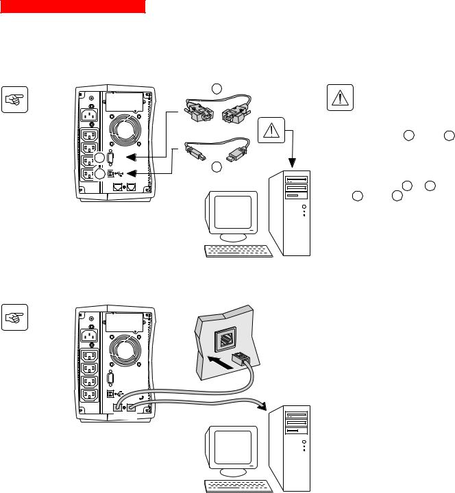
A Pulsar Evolution 1500 tower UPS has been used below to illustrate the instructions. The principle is the same for all the other tower and rack models.
2.4 Connection to the RS232 or USB communications port (optional)
|
21 |
The RS232 and USB |
|
|
communications ports cannot |
|
|
operate simultaneously. |
|
|
1 - Connect the RS232 21 or USB 22 |
|
|
communications cable to the serial port or |
2 |
RS232 |
the USB port on the computer. |
|
|
|
1 |
22 |
|
|
2 - Connect the other end of the |
|
|
|
communications cable 21 or 22 to the |
|
|
RS232 2 or USB 1 communications |
|
|
port on the UPS. |
|
|
The UPS can now communicate with all |
|
|
MGE UPS SYSTEMS supervision, set-up or |
|
|
safety software. |
2.5 Connection to the data-line protection port (optional)
The data-line protection function on the UPS eliminates overvoltages flowing on the computer-network lines.
Simply connect the line to be protected to the UPS using the data-line protection connectors (IN and OUT) as indicated opposite (RJ45 cables not supplied).
RS232
IN OUT 
DATA LINE
PROTECTION
Page 16 - 34007117EN/AB
2. Installation
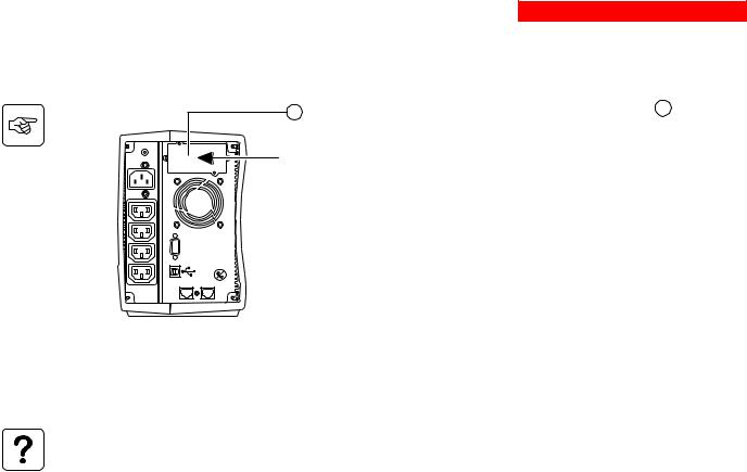
2.6 Installation of the communications-card option
4 |
1 |
- Remove the slot cover 4 secured by |
|
|
two screws. |
||
Restricted-access slot for |
2 |
- Insert the card in the slot. |
|
the communications card |
|||
|
|
||
|
3 |
- Secure the cover with the two screws. |
|
RS232
DATA LINE PROTECTION
IN OUT
It is not necessary to shut down the UPS to install the communications card.
This operation must be carried out by qualified personnel.
34007117EN/AB - Page 17
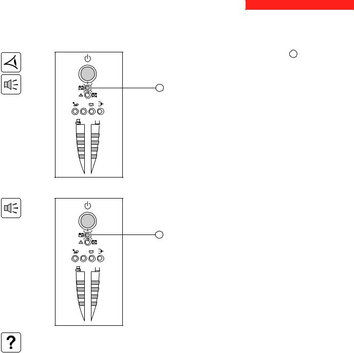
3. Operation
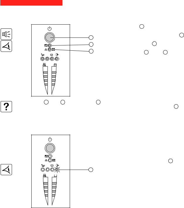
3.1 Start-up
 1 2
1 2
%
%
Press the ON / OFF button 10 .
The buzzer beeps and all the LEDs come ON.
The buzzer beeps twice during the self-test, then button 10 remains
10
ON, indicating that the outlets are supplied with power.
11- AC power is present: Only button 10 is ON. The protected equipment is supplied by the AC-power source.
12- AC power is absent: Button 10 and LED 11 are ON. The protected equipment is supplied by the UPS, operating on battery power.
All the connected equipment is supplied with power.
If button 10 or LED 11 are not ON or if LED 12 is ON, there is a fault (see section 4.1).
Note: The battery is charged as soon as the UPS is connected to the AC-power source, even if button 10 is in the OFF position.
3.2 Shift to booster or fader mode
(during voltage variations in the AC-input power)
 1 2
1 2
16
%
%
The booster and fader functions maintain the output voltage supplied by the UPS within close tolerances around the rated value even if significant voltage variations occur in the AC-input power. This avoids calling on battery power.
The values defining the voltage range may be set using the UPS Driver software.
During operation in booster or fader mode, LED 16 is ON, signalling a significant voltage variation in the AC-input power.
Page 18 - 34007117EN/AB
3. Operation
3.3 Operation on battery power (following failure of AC-input power)
Transfer to battery power
The AC-input power is out of tolerances, LED 11 goes ON.
During operation on battery power, the buzzer beeps every ten seconds.
The equipment connected to the UPS is supplied by the battery.
11
 1 2
1 2
%
%
Threshold for the low-battery warning
11
 1 2
1 2
%
%
When the threshold is reached, the buzzer beeps every three seconds. The low-battery warning threshold can be set by the user, with the “UPS Driver” software.
There is very little remaining battery backup time. Close all applications because UPS automatic shutdown is imminent.
When the battery reaches the end of its backup time, the UPS shuts down and all the LEDs go OFF.
The equipment is no longer supplied with power.
The UPS automatically restarts when power returns.
If the UPS does not restart, check that the “automatic restart when power returns” function has not been disabled (see section 3.4 Personalisation).
34007117EN/AB - Page 19
3. Operation
3.4 Personalisation (optional)
Function
Personalisation parameters can be set and modified using the UPS Driver software installed on a computer that is connected to the UPS (see section 2.4 Connection to the RS232 communications port).
Check that the RS232 21 communications cable is connected.
UPS Driver installation:
1 - Insert the Solution-Pac CD-ROM containing the UPS Driver software in the drive of a PC running Windows. 2 - Open the Windows File manager or Explorer and select the CD-ROM drive.
3 - Double-click "\Emb\Evolutio\Config\upsdriv.exe".
Once UPS Driver has been installed, UPS parameters can be modified in a window containing a number of tabs, each presenting a set of parameters :
ON / OFF conditions tab
Configurable function |
Default setting |
Options |
|
|
|
Automatic restart |
Enabled |
Disabled |
|
|
|
Cold start |
Enabled |
Disabled |
|
|
|
Forced reboot |
Enabled |
Disabled |
|
|
|
Energy saving |
Disabled |
Enabled |
|
|
|
UPS ON / OFF via software |
Enabled |
Disabled |
|
|
|
Battery tab
Configurable function |
Default setting |
Options |
|
|
|
|
|
Every day |
Interval between automatic battery tests |
Once a week |
Once a month |
|
|
No test |
|
|
|
Low-battery warning threshold |
20% of the remaining battery |
10 to 40% of the remaining battery |
|
backup time |
backup time |
|
|
|
Protection against deep discharges |
Enabled |
Disabled |
|
|
|
Page 20 - 34007117EN/AB

3. Operation
Voltage-thresholds tab
Configurable function |
|
Default setting |
Options |
|
|
|
|
|
|
Output voltage on battery power |
|
230 V |
200 V - 220 V - 240 V |
|
|
|
|
|
|
Upper threshold for transfer to battery power |
|
294 V |
271 to 294 V |
|
|
|
|
|
|
Fader-mode cut-in threshold |
|
265 V |
244 to 265 |
V |
|
|
|
|
|
Booster-mode cut-in threshold |
|
184 V |
184 to 207 |
V |
|
|
|
|
|
Lower threshold for transfer to battery power |
|
160 V |
160 to 180 |
V |
|
|
|
|
|
Maximum input-voltage range |
|
Disabled |
Enabled (1) |
|
|
|
|
|
|
(1) Lower threshold for transfer to battery power = 150 V |
|
|
|
|
Sensitivity tab
Configurable function |
Default setting |
Options |
|
|
|
UPS sensitivity level |
Normal |
High or low |
|
|
|
For more informations about these settings, refer to the Help function of the "UPS Driver" software.
34007117EN/AB - Page 21

4.Maintenance
4.1Trouble-shooting
Troubleshooting not requiring MGE UPS SYSTEMS after-sales support (all versions)
|
Indication |
Signification |
|
|
|
|
|
LED |
13 |
flashes and the |
UPS overload. The power drawn by the connected |
buzzer beeps once. |
equipment exceeds UPS capacity. |
||
|
|
|
|
LED |
12 |
flashes. |
A battery fault was detected during the automatic |
|
|
|
battery test. |
|
|
|
|
Correction
Check the power drawn by the equipment and disconnect any nonpriority devices.
Replace the battery module (see section 4.2).
Troubleshooting requiring MGE UPS SYSTEMS after-sales support
Indication |
Signification |
Correction |
|
|
|
LED 12 goes ON and |
UPS electronics have detected a UPS fault. |
|
the buzzer sounds |
The connected equipment is no longer supplied. |
|
continuously. |
|
Call the after-sales support |
|
The equipment connected to the UPS is no |
department. |
|
longer protected. |
|
|
|
|
Page 22 - 34007117EN/AB
4. Maintenance
4.2 Replacement of the battery module
Safety rules
Batteries constitute a danger (electrical shock, burns). The short-circuit current may be very high. Precautions must be taken for all handling:
remove all watches, rings, bracelets and any other metal objects;
use tools with insulated handles.
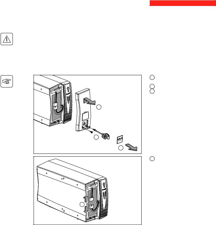
Tower models
Removal of the battery module
This operation may be carried out with the UPS supplying power to the load.
|
|
|
C |
P U |
L S |
A R |
|
|
|
|
|
Evolution |
|||
1 5 |
0 |
0 |
|
|
|
|
|
|
|
|
B |
|
|
|
A |
A - Unclip the small plate with the MGE logo on the front panel of the UPS.
B - Remove the two screws.
C - Remove the left-hand side of the front panel by pulling it slightly up and then forward.
D - Disconnect the battery module by pulling apart the connectors (never pull on the cables).
D
34007117EN/AB - Page 23
4. Maintenance
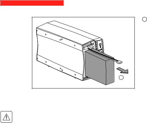
E |
E - Remove the battery module by pulling on the plastic tab and proceed with replacement.
Installation of the new battery module
Carry out the above operation in reverse order.
Caution: risk of electric arc when connecting the battery.
To maintain an identical level of performance and safety, use a battery module identical to that previously mounted in the UPS.
Press the two parts of the battery connector tightly together to ensure proper connection.
Page 24 - 34007117EN/AB
4. Maintenance
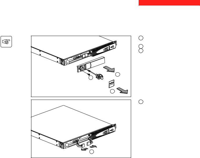
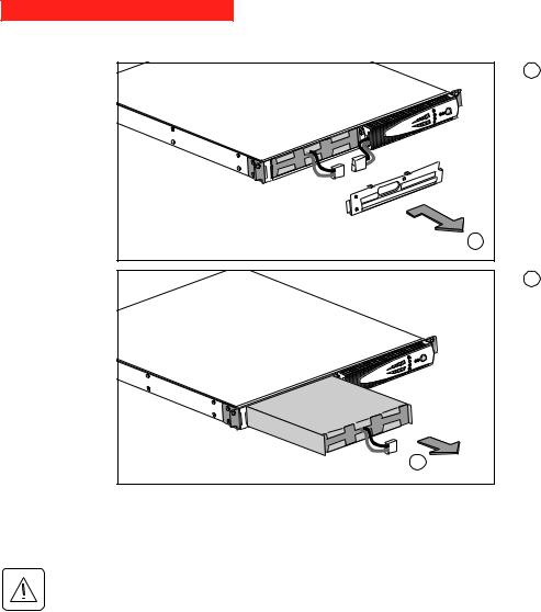
Rack models
Removal of the battery module
This operation may be carried out with the UPS supplying power to the load.
P U |
L S |
A R |
Evolution0 |
||
1 5 |
0 |
|
C
B
A - Unclip the small plate with the MGE logo on the front panel of the UPS.
B - Remove the two screws.
C - Remove the left-hand side of the front panel by pulling it forward.
A
D - Disconnect the battery module by pulling apart the connectors (never pull on the cables).
D
34007117EN/AB - Page 25
4. Maintenance
E - Remove the cover.
E
F - Remove the battery module by pulling on the plastic tab and proceed with replacement.
F
Installation of the new battery module
Carry out the above operation in reverse order.
Caution: risk of electric arc when connecting the battery.
To maintain an identical level of performance and safety, use a battery module identical to that previously mounted in the UPS.
Press the two parts of the battery connector tightly together to ensure proper connection.
Page 26 - 34007117EN/AB

5. Environment
This product has been designed to respect the environment:
It does not contain CFCs or HCFCs.
UPS recycling at the end of service life:
MGE UPS SYSTEMS undertakes to recycle, by certified companies and in compliance with all applicable regulations, all UPS products recovered at the end of their service life (contact your MGE branch office).
Packing:
UPS packing materials must be recycled in compliance with all applicable regulations.
Warning:
This product contains lead-acid batteries. Lead is a dangerous substance for the environment if it is not properly recycled by specialised companies.
Web site: www.mgeups.com
34007117EN/AB - Page 27
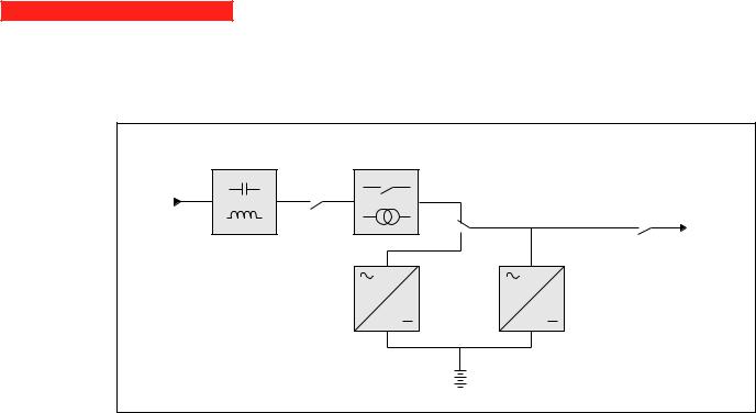
6. Appendices
6.1 Technical data
Simplified diagram
Filter |
Booster / fader transformer |
|
Input |
|
|
|
|
Output |
|
Inverter |
Charger |
|
|
Battery |
Page 28 - 34007117EN/AB

6. Appendices
Technical characteristics
Pulsar Evolution |
500 |
|
800 / 800 rack |
|
1100 / 1100 rack |
|
1500 / 1500 rack |
|
|
|
|
|
|
|
|
|
|
Output rating |
500 VA / 350 W |
|
800 VA / 560 W |
|
1100 VA / 700 W |
|
1500 VA / 1000 W |
|
|
|
|
|
|
|
|
|
|
AC-input power |
|
|
|
|
|
|
|
|
Voltage |
|
|
Single-phase, 160 V to |
294 V (1) , 230V nominal. |
|
|
||
Frequency |
47 Hz to 70 |
Hz (50 Hz system) or |
56.5 Hz to 70 Hz (2) (60 |
Hz system) |
||||
|
|
|
|
|
|
|
|
|
Output power (operation |
|
|
|
|
|
|
|
|
on battery power) |
|
|
|
|
|
|
|
|
Voltage |
|
|
Single-phase, 230 |
|
V (3) (+ 6% / - 10%) |
|
|
|
Frequency |
|
|
50/60 Hz |
|
+/- 0.1 Hz |
|
|
|
|
|
|
|
|
|
|
|
|
Battery (sealed lead-acid, |
|
|
|
|
|
|
|
|
maintenance free) |
|
|
|
|
|
|
|
3 x 12 V - 9 Ah, |
Tower models |
|
|
2 x 12 V - 7.2 Ah, |
|
2 x 12 V - 9 Ah, |
|
||
Rack models |
2 x 6 V - 9 Ah, |
|
4 x 6 V - 7.2 Ah |
|
4 x 6 V - 9 Ah |
|
6 x 6 V - 9 Ah |
|
|
|
|
|
|
|
|
|
|
Environment |
|
|
|
|
|
|
|
|
Noise level (operation on |
|
|
<40 dBA |
|
|
|
|
<40 dBA |
AC-input power) |
|
|
|
|
|
|
|
|
Operating temperature |
|
|
0 to 35° C |
|
|
|
|
0 to 40° C |
Relative humidity |
|
|
|
|
|
|
|
|
(without condensation) |
|
|
20 to 90% |
|
|
|
|
20 to 90% |
|
|
|
|
|
|
|
|
|
(1)The upper and lower thresholds may be set using the UPS Driver software.
(2)Or 40 Hz in low-sensitivity mode (may be set using the UPS Driver software).
(3)Adjustable from 200 to 240 V using the UPS Driver software.
34007117EN/AB - Page 29
 Loading...