


INSTRUCTION MANUAL
Meade® #1697 Computer Drive System
For LXD 650 and LXD 750 Equatorial Mounts
 Meade Instruments Corporation

MEADE LIMITED WARRANTY
Every Meade telescope, spotting scope, and telescope accessory is warranted by Meade Instruments Corporation (“Meade”) to be free of defects in materials and workmanship for a period of ONE YEAR from the date of original purchase in the U.S.A. and Canada. Meade will repair or replace a product, or part thereof, found by Meade to be defective, provided the defective part is returned to Meade, freight-prepaid, with proof of purchase. This warranty applies to the original purchaser only and is non-transferable. Meade products purchased outside North America are not included in this warranty, but are covered under separate warranties issued by Meade international distributors.
RGA Number Required: Prior to the return of any product or part, a Return Goods Authorization (RGA) number must be obtained from Meade by writing, or by calling (949) 451-1450. Each returned part or product must include a written statement detailing the nature of the claimed defect, as well as the owner’s name, address, and phone number.
This warranty is not valid in cases where the product has been abused or mishandled, where unauthorized repairs have been attempted or performed, or where depreciation of the product is due to normal wear-and-tear. Meade specifically disclaims special, indirect, or consequential damages or lost profit which may result from a breach of this warranty. Any implied warranties which can not be disclaimed are hereby limited to a term of one year from the date of original retail purchase.
This warranty gives you specific rights. You may have other rights which vary from state to state.
Meade reserves the right to change product specifications or to discontinue products without notice.
This warranty supersedes all previous Meade product warranties.
- 3 -
Contents
#1697 Computer Drive System
Introduction . . . . . . . . . . . . . . . . . . . . . . . . . . . . . . . . . . . . . . . . 4 Installation. . . . . . . . . . . . . . . . . . . . . . . . . . . . . . . . . . . . . . . . . 4 Quick Start . . . . . . . . . . . . . . . . . . . . . . . . . . . . . . . . . . . . . . . . 5 Basic Telescope Setup . . . . . . . . . . . . . . . . . . . . . . . . . . . 5 Basic CDS Setup . . . . . . . . . . . . . . . . . . . . . . . . . . . . . . . 6
Entering the Latitude and Longitude of the Observing Site . . . . . . . . . . . . . . . . . . . . . . . . . . . . . 6 Entering the Local Time and Date . . . . . . . . . . . . . . 6 Telescope and CDS Alignment. . . . . . . . . . . . . . . . . 7
Using the #1697 Computer Drive System . . . . . . . . . . . . . . . . 8 The Mode Key . . . . . . . . . . . . . . . . . . . . . . . . . . . . . . . . . 8 Library Object Keys . . . . . . . . . . . . . . . . . . . . . . . . . . . . . 8 Daytime Slewing. . . . . . . . . . . . . . . . . . . . . . . . . . . . . . . . 9 The CDS Keypad Hand Controller . . . . . . . . . . . . . . . . . . . . . . 9 ENTER Key . . . . . . . . . . . . . . . . . . . . . . . . . . . . . . . . . . . 9 MODE Key . . . . . . . . . . . . . . . . . . . . . . . . . . . . . . . . . . . . 9 GO TO Key. . . . . . . . . . . . . . . . . . . . . . . . . . . . . . . . . . . 10
Direction Keys . . . . . . . . . . . . . . . . . . . . . . . . . . . . . . . . 10 RET Key . . . . . . . . . . . . . . . . . . . . . . . . . . . . . . . . . . . . . 10 Speed Keys . . . . . . . . . . . . . . . . . . . . . . . . . . . . . . . . . . 10 FOCUS Key . . . . . . . . . . . . . . . . . . . . . . . . . . . . . . . . . . 10 MAP Key. . . . . . . . . . . . . . . . . . . . . . . . . . . . . . . . . . . . . 10 Object Keys . . . . . . . . . . . . . . . . . . . . . . . . . . . . . . . . . . 10 PREV and NEXT Keys . . . . . . . . . . . . . . . . . . . . . . . . . . 10
The CDS Control Panel . . . . . . . . . . . . . . . . . . . . . . . . . . . . . 10 Current (mA x 100) . . . . . . . . . . . . . . . . . . . . . . . . . . . . . 10 N/S . . . . . . . . . . . . . . . . . . . . . . . . . . . . . . . . . . . . . . . . 11 On/Off . . . . . . . . . . . . . . . . . . . . . . . . . . . . . . . . . . . . . . . 11 Red LED Indicator . . . . . . . . . . . . . . . . . . . . . . . . . . . . . 11 Focuser. . . . . . . . . . . . . . . . . . . . . . . . . . . . . . . . . . . . . . 11 Reticle. . . . . . . . . . . . . . . . . . . . . . . . . . . . . . . . . . . . . . . 11 Keypad . . . . . . . . . . . . . . . . . . . . . . . . . . . . . . . . . . . . . . 11 R.A. Motor. . . . . . . . . . . . . . . . . . . . . . . . . . . . . . . . . . . . 11 Power 12vDC . . . . . . . . . . . . . . . . . . . . . . . . . . . . . . . . . 11 RS-232 . . . . . . . . . . . . . . . . . . . . . . . . . . . . . . . . . . . . . . 11 CCD . . . . . . . . . . . . . . . . . . . . . . . . . . . . . . . . . . . . . . . . 11 Aux . . . . . . . . . . . . . . . . . . . . . . . . . . . . . . . . . . . . . . . . 11
MODE Functions . . . . . . . . . . . . . . . . . . . . . . . . . . . . . . . . . . 11 MODE ONE: TELESCOPE/OBJECT LIBRARY . . . . . . 11 TELESCOPE Menu File . . . . . . . . . . . . . . . . . . . . . 11 SITE. . . . . . . . . . . . . . . . . . . . . . . . . . . . . . . . . 11 ALIGN . . . . . . . . . . . . . . . . . . . . . . . . . . . . . . . 11 SMART . . . . . . . . . . . . . . . . . . . . . . . . . . . . . . 12 Training the SMART Drive . . . . . . . . . . . . . . 12 DEC LEARN . . . . . . . . . . . . . . . . . . . . . . . . 12 12/24 HR . . . . . . . . . . . . . . . . . . . . . . . . . . . . . 12 HELP . . . . . . . . . . . . . . . . . . . . . . . . . . . . . . . . 13 REVERSE NS . . . . . . . . . . . . . . . . . . . . . . . . . 13 REVERSE EW . . . . . . . . . . . . . . . . . . . . . . . . 13 BALANCING . . . . . . . . . . . . . . . . . . . . . . . . . . 13 High Precision Pointing . . . . . . . . . . . . . . . . . . 13 Pointing Accuracy. . . . . . . . . . . . . . . . . . . . . 13
Using High Precision Pointing . . . . . . . . . . . 13
SLEW RATE . . . . . . . . . . . . . . . . . . . . . . . . . . 14
®The name ‘Meade’ and the Meade logo are trademarks registered with the U.S. Patent Office and in principal countries throughout the world.
© 1998 Meade Instruments Corporation
DEC Backlash Compensation. . . . . . . . . . . . . 14 PIER . . . . . . . . . . . . . . . . . . . . . . . . . . . . . . . . 14 OBJECT LIBRARY Menu File . . . . . . . . . . . . . . . . 14 OBJECT INFO. . . . . . . . . . . . . . . . . . . . . . . . . 14 START FIND . . . . . . . . . . . . . . . . . . . . . . . . . . 15 Coordinate Matching Feature. . . . . . . . . . . . 15 FIELD . . . . . . . . . . . . . . . . . . . . . . . . . . . . . . . 15 PARAMETERS . . . . . . . . . . . . . . . . . . . . . . . . 15 TYPE GPDCO . . . . . . . . . . . . . . . . . . . . . . 15 BETTER . . . . . . . . . . . . . . . . . . . . . . . . . . . 15 HIGHER . . . . . . . . . . . . . . . . . . . . . . . . . . . 16 LARGER . . . . . . . . . . . . . . . . . . . . . . . . . . . 16 SMALLER . . . . . . . . . . . . . . . . . . . . . . . . . . 16 BRIGHTER . . . . . . . . . . . . . . . . . . . . . . . . . 16 FAINTER. . . . . . . . . . . . . . . . . . . . . . . . . . . 16 RADIUS . . . . . . . . . . . . . . . . . . . . . . . . . . . 16
MODE TWO: COORDINATES/GOTO. . . . . . . . . . . . . . 16
Coordinates Menu Option . . . . . . . . . . . . . . . . . . . 16 GO TO Menu Option . . . . . . . . . . . . . . . . . . . . . . . 16 MODE THREE: CLOCK/CALENDAR . . . . . . . . . . . . . . 17 MODE FOUR: TIMER/FREQ . . . . . . . . . . . . . . . . . . . . 17 TIMER Option. . . . . . . . . . . . . . . . . . . . . . . . . . . . . 17 FREQ Option . . . . . . . . . . . . . . . . . . . . . . . . . . . . . 17 MODE FIVE: KEYPAD OFF/BRIGHTNESS ADJUST. . 17
Optional Accessories . . . . . . . . . . . . . . . . . . . . . . . . . . . . . . . 18 Meade Customer Service . . . . . . . . . . . . . . . . . . . . . . . . . . . . 18
Appendix A: Precise Polar Alignment . . . . . . . . . . . . . . . . . . 19
Appendix B: Alignment Star Library and Star Charts . . . . . . 20
Alignment Stars . . . . . . . . . . . . . . . . . . . . . . . . . . . . . . . 20
Star Charts (for Northern Hemisphere Observers) . . . . 21
Appendix C: #1697 CDS 64,359-Object Library . . . . . . . . . . 23
Overview: 64,359 Object Library. . . . . . . . . . . . . . . . . . 23
Accessing the Object Databases . . . . . . . . . . . . . . . . . . 23
Messier (M) Catalog . . . . . . . . . . . . . . . . . . . . . . . . 23
Planets and Moon . . . . . . . . . . . . . . . . . . . . . . . . . 23
Star, SAO & GCVS Catalogs . . . . . . . . . . . . . . . . . 23
CNGC, IC, & UGC Catalogs . . . . . . . . . . . . . . . . . 24
The Meade CNGC Catalog . . . . . . . . . . . . . . . . . . . . . . 24
Star Catalog (listing). . . . . . . . . . . . . . . . . . . . . . . . . . . . 27
M Catalog (listing) . . . . . . . . . . . . . . . . . . . . . . . . . . . . . 34
Appendix D: Personal Computer Control of the #1697 CDS . 36
RS-232 Cable . . . . . . . . . . . . . . . . . . . . . . . . . . . . . . . . . 36
CDS Test Program . . . . . . . . . . . . . . . . . . . . . . . . . . . . . 37
CDS Command Set . . . . . . . . . . . . . . . . . . . . . . . . . . . . 38
Command Set Formats . . . . . . . . . . . . . . . . . . . . . 38
General Telescope Information . . . . . . . . . . . . . . . 39
Telescope Motion . . . . . . . . . . . . . . . . . . . . . . . . . . 40
Library/Objects . . . . . . . . . . . . . . . . . . . . . . . . . . . . 40
Miscellaneous. . . . . . . . . . . . . . . . . . . . . . . . . . . . . 42
Keypad Hand Controller Specific . . . . . . . . . . . . . . 44
CDS Demo Program . . . . . . . . . . . . . . . . . . . . . . . . . . . 44
Appendix E: Care and Maintenance of the CDS. . . . . . . . . . 50
- 4 -
#1697 COMPUTER DRIVE SYSTEM:
INTRODUCTION
The Meade #1697 Computer Drive System (CDS) is easily installed in the Meade LXD 650 and 750 Equatorial Mounts. With a properly polar aligned mount, (see the instruction manual which accompanies the telescope), the #1697 Computer Drive System's advanced electronics permit the location and observation of the major planets as well as hundreds of deep-sky objects the very first night of use. Its 64,359-object library provides enough galaxies, nebulae, star clusters, and other deep sky objects for a lifetime of observing enjoyment.
Please take a few minutes to read this manual and become familiar with all of the #1697 Computer Drive System's capabilities.
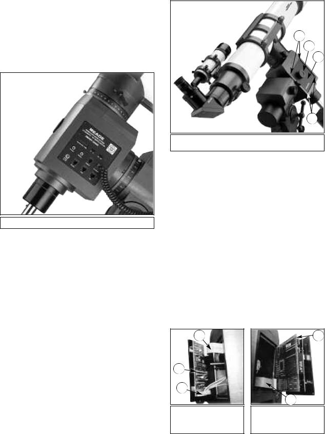
Fig. 1 #1697 Computer Drive System.
INSTALLATION
For the #1697 CDS to function properly, there are two printed circuit boards that need to be installed into the Declination housing of the LXD Equatorial Mounts.
The CDS printed circuit boards are sensitive to static electricity and should be handled with care to avoid damage. Whenever handling the electronics, be sure to observe the following precautions:
Installing the CDS is a straightforward procedure, requiring only a phillips screwdriver, and hex wrench.
1.On the LXD Equatorial Mount, remove the rubber knurling on the Declination slow-motion knob (2), Fig. 2, and remove this knob by loosening the hex set screw.
1
2
3
1
Fig. 2 Installing the Printed Circuit Boards. (1) Phillips-Head Screws; (2) Declination Slow-Motion Knob; (3) Cover Plate.
2.Remove the four screws (1), Fig. 2, holding the cover plate (3), Fig. 2, on the Declination slow-motion knob side of the mount. Discard this cover plate.
3.Inside the Declination housing, you will see the Declination motor and cord with connector. Attach the Dec motor cord, (3), Fig. 3, to the Driver printed circuit board (PCB), (2), Fig. 3. Note the correct orientation of the connector, as shown in Fig. 3.
4.On the Driver PCB, on the opposite side of the Dec motor cord (3), Fig. 3, look for a piece of electrical tape covering the circuitry. If the tape is not in place and the circuitry is visible, place a piece of electrical tape over this area to prevent the contacts from rubbing against the polar shaft during the installation process. Leave the electrical tape in place after the Driver PCB is installed.
5.The Driver PCB has a 16-pin ribbon cable (1), Fig. 3 already attached to the new cover plate. Feed this cable into the Declination housing as shown in Fig. 3.
6.Place the Driver PCB into the Declination housing and replace the four Phillips-head screws, (1), Fig. 2, to hold the new cover plate in place.
•Leave the printed circuit boards in the static-resistant bags until ready to install them into the Declination housing.
•When making the installation, avoid standing on a carpeted floor. Instead, stand on a formica or wood floor surface when installing the boards.
•Limit your movements while installing the printed circuit boards, as unnecessary movement can increase the chance of static build-up and discharge.
•Discharge yourself by touching the metal of the telescope before you touch the printed circuit boards.
•Always handle the printed circuit boards by the edges; avoid touching any of the components.
1
2
3
Fig. 3 CDS Driver Printed
Circuit Board. (1) 16-Pin
Ribbon Cable; (2) Driver PCB;
(3) Dec Motor Cable.
1
2
Fig. 4 CDS Printed Circuit
Board. (1) CDS PCB;
(2) 16-Pin Ribbon Cable

- 5 -
7.Replace the Declination slow-motion knob (2), Fig. 2. Lock in place by tightening the set screw, and replace the rubber knurling.
8.Remove the cover plate on the opposite side of the Declination housing, by removing the four Phillips-head screws holding it in place.
9.Route the 16-pin ribbon cable from the Driver PCB so that it exits the housing on the lower right-hand side. Be sure this cable does not cover the hole in the Declination shaft, which will block light from reaching the optional #814 Polar Alignment Finder should one be installed.
10.Connect the 16-pin ribbon cable (2), Fig. 4, to the CDS PCB (1), Fig. 4.
11.To position the CDS PCB into the Declination casting, first angle the top of the PCB into the opening, allowing it to clear the housing. Then, tilt the lower section of the CDS into the housing. Secure the CDS in place with the four screws.
12.Plug the RA motor coil cord into the R.A. motor port (8), Fig. 5 on the CDS Power Panel.
13.Plug the #1697 Keypad Hand Controller into the keypad port (7), Fig. 5, on the CDS Power Panel.
14.Plug in one of the provided power supplies: the AC Wall Adapter Power Converter, or the DC Cigarette Lighter Power Cord (used in an automobile's cigarette lighter outlet). The power supply plugs into the power port (9), Fig 5.
Installation of the #1697 CDS is now complete.
1 
2
4
3
Fig. 6: #1697 Keypad Hand Controller. (1) Display; (2) Direction Keys; (3) Speed Indicator LEDs; (4) Speed Selection Keys.
Basic Telescope Setup:
1.Polar align your telescope. See the instructions that accompany the telescope.
2.Turn "on" the #1697 Control Box. The Keypad Display (1), Fig. 6, displays “MEADE” for several seconds as the microprocessor does a self-diagnostic test. When the selfdiagnostic test is complete, the display shows “TELESCOPE” on the top line, and “OBJECT LIBRARY” on the lower line. The Speed Indicator LED (3), Fig. 6, next to the “SLEW” button is illuminated.
|
MEADE |
|
|
|
|||
|
COMPUTER DRIVE SYSTEM |
|
|
|
|||
|
LX QUARTZ - DC SERVO MOTOR |
|
|
|
|||
|
SMART DRIVE |
|
|
|
|
||
|
1 |
|
|
2 |
|
3 |
4 |
|
Current (mA x 100) |
N |
S |
On |
Off |
8 |
|
|
|
|
|
|
|||
5 |
|
|
|
|
|
|
|
6 |
|
7 |
|
|
|
|
|
|
Focuser |
Reticle |
|
|
|
|
12 |
9 |
10 |
|
11 |
Keypad |
|
RA Motor |
|
|
|
|
|||||
|
|
|
|
|
|||
|
Power |
RS 232 |
|
CCD |
|
Aux |
|
|
12vDC |
|
|
|
|||
Fig. 5: #1697 Control Panel. (1) Current Indicator (Ammeter);
(2) North/South Switch; (3) On/Off Switch; (4) LED Indicator Light;
(5) Focuser Port; (6) Reticle Port; (7) Keypad Hand Controller Port;
(8) R.A. Motor Port; (9) Power Port; (10) RS-232 Port; (11) CCD Port; (12) Aux Port.
QUICK START
Although the electronics within the #1697 Computer Drive System are advanced, the system is very straightforward to operate—even for the beginning observer. This section is designed as a "quick start" section for those observers anxious to begin. Be sure to come back and read the more detailed sections of this manual. Most of the system’s features cannot be accessed without full knowledge of these details.
3.At this point, the #1697 Computer Drive System is ready to use. Select a speed at which to move the telescope by pressing the appropriate Speed Selection Key (4), Fig 6. As a speed is selected, the red LED next to the selected speed lights up. Then press one of the four direction keys, (2), Fig. 6, to move the telescope in that direction at the selected speed.
4.With the CDS power turned on, the LXD mount can be moved in either of two ways: (1) By loosening the R.A. and Dec locks as described in the instruction manual supplied with your telescope; or (2) by using the N, E, W, or S keys
(2), Fig. 6, on the Keypad.
NOTE: Telescope movement can only been seen in the SLEW and FIND modes; CNTR (center) and GUIDE motions can only be seen while looking through the telescope.
DO NOT attempt to adjust the LXD Equatorial Mounts with the manual R.A. or Dec slow-motion controls when the CDS Drive is turned on. Serious damage to the drive motor assemblies could result.
Please note that it is possible for the telescope to hit one of the tripod legs while manually moving the LXD Equatorial Mount with the Keypad direction keys. The CDS software is programmed, however to avoid hitting the tripod legs provided the proper time, date, and site information has been entered, and that the telescope has been properly aligned, as described on page 7.
The quick start method described above allows you to use the telescope, but does not make any use of the computer features available. To utilize all the features of the #1697 Computer Drive System, it is necessary to enter some information into the

- 6 -
system’s computer memory. It is also necessary to learn the menu structure of the Keypad Hand Controller, which is described beginning on page 8.
Basic CDS Setup:
This section explains what keys to push to get the minimum data required into the computer system, without any detailed explanation. The detailed explanation can be found later in the manual. These steps will only take a few minutes and will allow immediate use of all of the CDS features.
In order for the CDS to utilize the stellar coordinate system, Right Ascension (R.A.) and Declination (Dec), the system needs to know three pieces of information: the location (latitude and longitude) of the observing site; the local time; and the date. This information only needs to be entered one time — the CDS remembers the data even when the power is off.
1)Entering the Latitude and Longitude of the Observing Site.
The position of your observing site should be determined as accurately as possible, to within 1 or 2 minutes of arc in both latitude and longitude. Many automobile, pilot, and topographical maps, as well as most atlases show latitude and longitude in 15 minute increments or better. The accuracy of the CDS depends on the accuracy of the data that is entered.
Once the above information is determined, it is easiest to enter the data into the system while the telescope and CDS are indoors where there is light—do not try to do it outside at night.
The following example is for an observing site in Costa Mesa, CA (LAT=33°35', LONG=117°42'). If a mistake is made during entry, simply turn off the telescope and restart this procedure. (A more detailed description of the procedure shown below can be found on page 11, "SITE".)
1.Turn "On" the #1697 CDS. After a few seconds (after the self-diagnostic test is complete), the display will look like Display 1.
→TELESCOPE OBJECT LIBRARY
Display 1
2.Press the ENTER key to select the TELESCOPE functions. The display should look like Display 2.
→1) A A A 2) A A A
Display 4
5.Press the ENTER key. The display should look like Display 5. (Number values may vary.)
→LAT |
= |
+00° |
00’ |
LONG |
= |
000° |
00’ |
|
|
|
|
Display 5
6.Use the number keys to enter your latitude. Mistakes may be corrected by moving the curser back, using the “E” and “W” keys. A negative latitude may be entered by positioning the cursor under the “+” and hitting the NEXT key. When the latitude is correctly entered, press ENTER. The curser moves to the LONG line. The display will look like Display 6.
LAT = +33° |
35’ |
|
→LONG = |
000° |
00’ |
|
|
|
Display 6
7.Use the number keys (as described above) to enter your longitude. When complete, the display will look like Display 7.
LAT = +33° 35’ →LONG = 117° 42’
Display 7
NOTE: The longitude standard used in the CDS starts at 0 degrees in Greenwich U.K. and increases Westerly only to 359 degrees 59 minutes. Many maps will show Easterly longitudes which cannot be entered into the Keypad Display (e.g., if the map indicates an observing site at an Easterly longitude of 18 degrees 27 minutes, it is necessary to enter the position as 341 degrees 33 minutes).
The differences in longitude and latitude as they pertain to different map spheroid projections are minor differences that are too small to adversely affect the longitude and latitude data input.
→1) SITE 2) ALIGN
Display 2
3.Press the ENTER key to select the SITE functions. The display should look like Display 3.
→1) A A A 2) A A A
Display 3
4.Press and Hold the ENTER key until the Keypad Hand Controller beeps. This selects the first site for editing. The display should look like Display 4, with the first “A” flashing
NOTE: To edit the letters "AAA", press the NEXT or PREV keys on the Keypad Hand Controller to cycle through the letters of the alphabet. Use the "E" and "W" keys to move between positions.
8.Press ENTER to complete the site information input. The display will go back to Display 3.
9.Press MODE to go back to Display 2.
10.Press MODE again to go back to Display 1.
2) Entering the Local Time and Date.
The local time should be set as accurately as possible using the 24 hour format. The pointing accuracy of the telescope depends on the accuracy of the time entered because the local time and date are used to determine sidereal time (star time). Choose a reliable source as a reference for accurate time such as your local airport, or telephone company. In the U.S.A. you can double check the accuracy of the exact minutes by dialing WWV for the universal coordinated time at (303) 499-7111 (be sure to enter your local time hour information, not the U.T. hour).
The following example is for 4:25:00 P.M. on Jan. 15, 1998.
1.The display should look like Display 1. If it does not, press the MODE key until it does.
 Loading...