


Instruction Manual
DS-114AT
Reflecting Telescope
 Meade Instruments Corporation
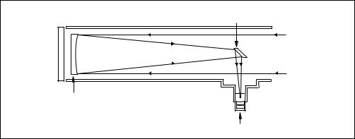
Reflecting Telescopes use a concave primary mirror to collect light and form an image. In the Newtonian type of reflector, light is reflected by a small, flat secondary mirror to the side of the main tube for observation of the image. Light is collected by a concave mirror and brought to a focus at F.
Secondary
Mirror
Concave |
F |
Mirror |
|
Reflecting Telescope |
Eyepiece |

WARNING!
Never use a Meade® DS-114AT Telescope to look at the Sun! Looking at or near the Sun will cause instant and irreversible damage to your eye. Eye damage is often painless, so there is no warning to the observer that damage has occurred until it is too late. Do not point the telescope or its viewfinder at or near the Sun. Do not look through the telescope or its viewfinder as it is moving. Children should always have adult supervision while observing.
CAUTION:
Use care to install batteries as indicated by the battery compartment. Follow battery manufacturer's precautions. Do not install batteries backward or mix new and used batteries. Do not mix battery types. If these precautions are not followed, batteries may explode, catch fire, or leak. Improperly installed batteries void your Meade warranty.
If you are anxious to use your DS-114AT Telescope for the first time, before a thorough reading of this instruction manual, see the QUICK-START GUIDE on page 4.
® The name “Meade” and the Meade logo are trademarks registered with the U.S. Patent Office and in principal countries throughout the world. All rights reserved.
© 2001 Meade Instruments Corporation.
CONTENTS |
|
Quick-Start Guide .......................................................... |
4 |
Telescope Features ...................................................... |
7 |
Autostar Features .......................................................... |
8 |
Getting Started .............................................................. |
10 |
Packing List .............................................................. |
10 |
How to Assemble Your Telescope ............................ |
10 |
Some Notes About the Dual-Motor System.............. |
11 |
The Viewfinder .......................................................... |
11 |
Focusing the Viewfinder ...................................... |
11 |
Aligning the Viewfinder ........................................ |
12 |
Choosing an Eyepiece ............................................ |
12 |
The Barlow Lens ...................................................... |
12 |
Observing ...................................................................... |
13 |
Observing by Moving the Telescope Manually ........ |
13 |
Terrestrial Observing ................................................ |
13 |
Observing Using Autostar's Arrow Keys .................. |
13 |
Slew Speeds ............................................................ |
14 |
Observe the Moon .................................................... |
14 |
Astronomical Observing ............................................ |
14 |
Tracking an Object Automatically.............................. |
14 |
Alt/Az Home Position .......................................... |
15 |
Moving Through Autostar’s Menus...................... |
15 |
Initializing Autostar .............................................. |
15 |
Training the Drive ................................................ |
16 |
Observe a Star Using Automatic Tracking .......... |
17 |
Easy (Two-Star) Align .............................................. |
17 |
Two-Star Alt/Az Alignment ........................................ |
18 |
One-Star Alt/Az Alignment ........................................ |
18 |
Go To Saturn ............................................................ |
19 |
Take a Guided Tour .................................................. |
19 |
Basic Autostar Operation................................................ |
20 |
Autostar Navigation Exercise .................................... |
20 |
Entering Numbers and Text into Autostar ................ |
21 |
Navigating Autostar .................................................. |
21 |
Adjusting the Speed of a Scrolling Message ............ |
21 |
Menus and Menu Options .............................................. |
22 |
Complete Autostar Menu Structure .......................... |
22 |
Object Menu.............................................................. |
22 |
Event Menu .............................................................. |
23 |
Glossary Menu.......................................................... |
24 |
Utilities Menu ............................................................ |
24 |
Setup Menu .............................................................. |
25 |
Caring for Your Telescope ............................................ |
28 |
Collimation ................................................................ |
28 |
Specifications ............................................................ |
30 |
Optional Accessories ...................................................... |
31 |
Meade Customer Service ........................................ |
31 |
Appendix A: Locating the Celestial Pole ........................ |
32 |
Appendix B: To Find Objects Not in the Database ........ |
33 |
Appendix C: Observing Satellites .................................. |
34 |
Basic Astronomy ............................................................ |
35 |
3

QUICK-START GUIDE
This Quick Start procedure explains how to set up your DS-114AT for manual viewing. If you wish to make observations using the Autostar handbox, please turn to HOW TO ASSEMBLE YOUR TELESCOPE, page 10 and take the time and care necessary to assemble all the components that are supplied with this telescope.
1
2
 A
A
1.Remove the optical tube and tripod from the giftbox.
Perform this setup on a flat, stable surface. It is recommended that you perform this operation in the daytime or in bright light the first time you assemble the telescope.
The optical tube assembly is shipped with the cradle rings, yoke mount, and tripod attached. Carefully remove the assembly from the box. Lay the assembly on the floor.
2.Remove the optical tube from the mount.
The optical tube is shipped oriented the wrong direction in the yoke mount for observing—you must remove the tube from the mount and turn it around 180°.
Loosen the cradle ring lock knobs and move the knobs out of the way so that you can open the cradle rings. Once the rings are open, remove the optical tube from the cradle rings.
3.Stand the tripod and orient the cradle rings.
Stand the tripod on a flat surface and gently pull the legs apart to a fully open position. Turn the cradle rings so that the ring base is horizontal (parallel) to the ground. Tighten the alt lock (A) to a firm feel, so the rings remain in that position.
3
4

4
 B
B
 C
C
 D
D
5
6
7
4.Attach and balance the optical tube.
Turn the optical tube around and replace it into the cradle rings. Fasten the cradle rings lock knobs so that they only hold the optical tube loosely; do not tighten the lock knobs yet. Note the optical tube's and the yoke's orientation in photo.
Slide the tube back and forth until you find a position where the tube remains horizontal (i.e., without tipping up or down). Then tighten the cradle rings lock knobs to a firm feel.
5.Insert the eyepiece.
Remove the supplied 25mm eyepiece (B) from its container and place it into the eyepiece holder. Tighten the thumbscrews (C) to a firm feel only. Remove the dust cover from the end of optical tube assembly. Use the focus knobs (D) to bring objects into focus.
6.Adjust tripod.
Adjust the height of the tripod by lifting the clip on each leg and extending the sliding inner section of each tripod leg to the desired length. Then press the clip back against the leg to lock in place.
7.Sight along the tube.
Sight along the side of the telescope's main tube to locate an object and then observe through the eyepiece.
If you wish to attach the viewfinder, see page 10.
If you wish to initialize Autostar, see page 15.
If you wish to align the telescope, see page 17.
If you wish to use Autostar to automatically view objects, see page 19 for some examples.
5

|
7 |
6 |
5 |
4 |
|
|
|
|
3 |
|
|
|
|
3 |
Fig. 1c: Cradle Rings Lock |
8 |
|
|
|
Knobs (on opposite side). |
|
|
|
|
11 |
|
|
|
|
|
|
|
|
22 |
12 |
|
|
|
|
|
|
|
|
21 |
|
19 |
|
|
|
14 |
|
|
18 |
|
|
|
|
|
|
|
|
|
|
20 |
|
16 |
|
|
|
|
|
|
A |
B |
|
|
|
Fig. 1b (Inset): Computer Control Panel. |
|
|
|
|
(A) LED |
|
|
|
|
(B) 12V Port |
|
|
|
|
(C) Handbox Port |
|
|
|
|
(D) AZ Port |
|
DS-114AT Series Telescope. |
|
|
(E) ALT Port |
|
|
|
(F) AUX Port |
||
|
|
|
||
6

Want to learn more about the viewfinder? See pages 10 through 12.
Want to learn more about collimation?
See pages 29 and 30.
Want to learn more about
Autostar's
buttons?
See pages 8 and 9.
Autostar's
menus?
See pages 22 through 27.
TELESCOPE FEATURES
The DS-114AT telescope has a variety of useful features. Be sure to become acquainted with all of these controls before you begin making observations through the telescope.
Focus Knobs: Move the telescope’s focus drawtube in a finely-controlled motion to achieve precise image focus.
Eyepiece Holder: Holds the eyepiece in place.
Eyepiece Holder Thumbscrews (2): Tighten the eyepiece in place. Tighten to a firm feel only.
Eyepiece: Place one of the supplied eyepieces into the eyepiece holder (2, Fig. 1). objects than the main telescope eyepiece
screws to align the viewfinder. viewfinder to the telescope (11, Fig. 1).
the altitude of the optical tube.
Cradle Rings (2): Hold optical tube securely in place.
Cradle Ring Lock Knobs (2): Tighten to a firm feel to hold the optical tube securely in place. Fig. 1c depicts a cradle ring clamped in place by one of the lock knobs and one of the lock knobs hanging loose.
Optical Tube: The main optical component that gathers the light from distant objects and brings this light to a focus for observation with the eyepiece.
Primary Mirror Cell: Contains the optical tube's primary mirror and 3 screws that are used in a collimation adjustment. Note: Do not remove the piece of felt from the cell.
TIP: When a message is scrolling across the display, press and hold the Up Arrow key to increase the scrolling speed or press and hold the Down Arrow key to decrease the scrolling speed.
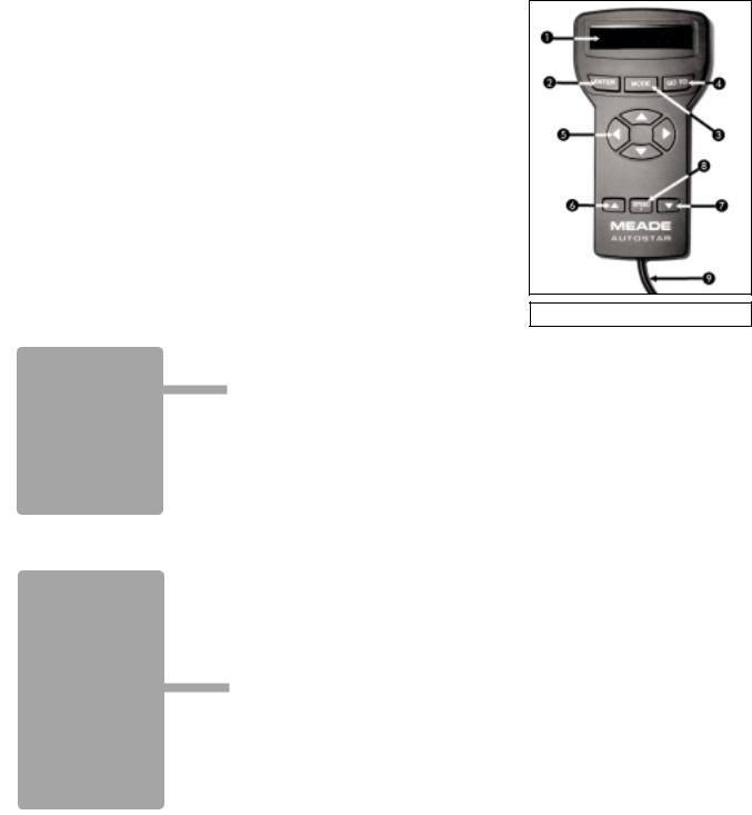
AUTOSTAR FEATURES
Control of the DS-114AT Series Telescopes is through the operation of the #494 Autostar handbox. Nearly all functions of the telescope can be operated with just a few pushes of Autostar’s buttons. Some of the major features of Autostar are:
■Automatically move the telescope to any of the 1400 objects stored in the database or manually enter the astronomical coordinates of any celestial object.
■Take a guided tour of the best celestial objects to view on any given night of the year.
■Access a glossary of astronomical terms.
■Calculate which eyepiece to use for optimum viewing of a celestial object.
Autostar has soft-touch keys and the LCD (Liquid
Crystal Display) is backlit with a red LED (Light
Emitting Diode) for easy viewing in the dark.
NOTE: Autostar does not require batteries; the Fig. 2: #494 Autostar Handbox. telescope’s batteries supply power to Autostar.
2-Line LCD: Displays Autostar menu and help information.
•Top line: Displays the menu or category name.
•Bottom line: Displays a menu option or information about a subject.
ENTER Key: When an option is displayed, press ENTER to enable the choice. When a menu is displayed, press ENTER to access the next menu or data level in the Autostar database. ENTER is similar to the RETURN key on a computer. See MOVING THROUGH AUTOSTAR'S MENUS, page 15 and MENUS AND MENU OPTIONS, page 22.
NOTE: If ENTER is pressed for two seconds or more and then released, Autostar emits a beep and “ENTER to Sync” is displayed. If the "ENTER to Sync" feature is accessed by mistake, press MODE to return to the previous screen. See HIGH PRECISION, page 26, for more details about this feature.
MODE Key: When a menu is displayed, press MODE to return to the previous menu or data to the ESCAPE key on a computer.
Item” level moves Autostar to the top-
two seconds or more, the following infor- (6 and 7, Fig. 2):
coordinates coordinates
menu.
currently selected object. While the telescope is time by pressing any key except GO TO.
.
The GO TO key also allows you to perform a "spiral search." A spiral search is useful when the telescope is commanded to go to an object, but that object is not visible in the eyepiece after the telescope finishes its search. (This sometimes occurs during the alignment procedure.) Press GO TO when the slew is finished and the telescope starts slewing in a spiral pattern at a very slow speed around the search area. Look through the eyepiece and when the object does become visible, press MODE to stop the spiral search. Then use the Arrow keys to center the object.
8

Want to learn more about slew speeds? See page 14.
down, left, and right), at any
of the alphabet and numerithe Up Arrow key starts with left and right across the LCD
display.
, Scroll Keys: Access options of the menu displayed on the top line of the screen. Options within the menu are displayed, one at a time, on the second line. Press the Scroll keys to move through the options. Press and hold a Scroll key to move quickly through the options, or to change scroll speeds of text.
The Scroll keys also scroll through the letters of the alphabet and numerical digits.
Tip: When a message is scrolling across the display, press and hold the Up Scroll key to increase the scrolling speed, or press and hold the Down Scroll key to decrease the scrolling speed.
NOTE: The Scroll Down key and the Down Arrow key move forward through the alphabet & digits (A to Z, 0 to 9). The Scroll Up key and the Up Arrow key move backward (Z to A, 9 to 0). Common symbols are also available in the list.
Speed/? Key: Press the Speed/? key to cycle through the nine slew speeds that move the telescope. Each time the Speed/? key is briefly pressed, the current speed will be shown for about two seconds on the display.
The Speed/? key also accesses the "Help" file. "Help" provides on-screen information for whatever task is currently active.
NOTE: Pressing the Speed/? key very briefly changes the slew speed. Holding down the Speed/? key longer (one to two seconds) accesses the Help function.
If you have a question about an Autostar operation (e.g., INITIALIZATION, ALIGNMENT, etc.), hold down the Speed/? key and follow the directions that scroll on the second line of the LCD screen. When a word appears in [brackets], press ENTER to access the Autostar Glossary. A definition or more detailed information is displayed. Press MODE to return to the scrolling Autostar Help display.
When satisfied with the Help provided, press MODE to return to the original screen and continue with the chosen procedure.
Coil Cord: Plug the Autostar coil cord into the HBX port (C, Fig. 1b) of the computer control panel.
9
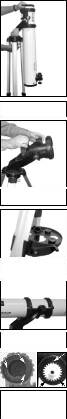
Fig. 3 Remove assembly from the giftbox.
Fig. 4: Adjust the cradle rings.
Fig. 5 Attach tray to the tripod:
Fig. 6: Attach and balance the optical tube.
Fig. 7: Motor (left) and gear (right) assembly. Note the slots and the locator tabs.
GETTING STARTED
Packing List
Assembling the telescope for the first time requires only a few minutes. When first opening the packing box, note carefully the parts listed on your giftbox.
How to Assemble Your Telescope
The telescope attaches directly to the tripod. The telescope in this way is "mounted" in an “Altazimuth” (“Altitude-Azimuth,” or “vertical-horizontal”) format. The telescope mounted this way moves along the vertical and horizontal axes, corresponding to the astronomical axes known as Declination (vertical) and Right Ascension (horizontal).
Perform this setup on a flat, stable surface. It is recommended that you perform this operation in the daytime or in bright light the first time you assemble the telescope.
1.Remove the optical tube and tripod from the giftbox: The optical tube assembly is shipped with the cradle rings (9, Fig. 1), yoke mount (21, Fig. 1), and tripod attached.
Carefully remove the assembly from the box. Lay the assembly on the floor.
2.Remove the optical tube from the mount: The optical tube (11, Fig. 1) is shipped oriented the wrong direction in the yoke mount for observing— you must remove the tube from the mount and turn it around 180°.
Loosen and unlatch the cradle ring lock knobs (10, Fig. 1) so that you can open the cradle rings (9, Fig. 1). Once the rings are open, remove the optical tube from the cradle rings. Carefully note the orientation of the tube, so that you can rotate it 180° later on when you replace it in the rings.
3.Stand the tripod and adjust the cradle rings: Stand the tripod on a flat surface and gently pull the legs (16, Fig. 1) apart to a fully open position. Turn the cradle rings so that the cradle ring base is horizontal (parallel) to the ground. Tighten the alt lock (22, Fig. 1), so the rings remain in the horizontal position.
4.Attach the utility tray to the tripod: Place one of the tray's flanges around one edge of a tripod leg and then pull the tray around until the other flange snaps in place (Fig. 5). The utility tray (17, Fig. 1) can be pushed up or down the tripod leg to a convenient height.
5.Attach and balance the optical tube: Turn the optical tube around 180° and replace it into the cradle rings. Fasten the cradle rings lock knobs (10, Fig. 1) so that they only hold the optical tube loosely; do not tighten the lock knobs yet.
|
Slide the tube back and forth until you find a position where the tube remains horizontal |
|
(i.e., without tipping up or down). Then tighten the cradle rings lock knobs to a firm feel. |
6. |
Attach the Alt (vertical) motor to the Alt gear: Place the knurled ring of the motor assem- |
|
bly over the Alt gear. Note that three small plastic tabs project outwards from the face of |
|
the gear (Fig. 7). These "locator" tabs fit into the mating slots inside the knurled ring. |
|
Wiggle the motor assembly over the gear assembly until the motor slips into place. Thread |
|
the knurled ring over the mating threads of the gear assembly to lock the motor. See Fig. |
|
8. Tighten to a firm feel only. |
7. |
Attach the Az (horizontal) motor to the Az gear: Attach the Az motor assembly to the |
|
the Az gear using the procedure described in step 6. See Fig. 9. |
8. |
Connect the motor assembly cords: Plug the cord from the alt motor assembly into the Alt |
|
port (E, Fig.1b) of the computer control panel. Plug the cord from the az motor assembly into |
|
the Az port (D, Fig.1b) of the computer control panel. |
9.Attach the viewfinder bracket: Use a Phillips-head screwdriver to thread the two attachment
screws in the viewfinder bracket (these screws are placed inside the bracket at the factory) into the mating threads located on the optical tube (Fig. 10).
10.Attach the viewfinder tube: Carefully remove the rubber eyecup from the viewfinder before sliding the viewfinder into the bracket. Then slide the viewfinder, eyepiece-end first (the end to which the rubber cup was attached) into the viewfinder bracket. Replace the rubber eyecup. Tighten the four alignment thumbscrews (6, Fig. 1 and Fig. 11) to a firmfeel to hold the viewfinder in the bracket.
11.Insert the eyepiece: Remove the supplied 25mm eyepiece from its container and place it into the eyepiece holder (2, Fig. 1). Tighten the thumbscrew (3, Fig. 1) to a firm feel only.
10
Fig. 8: Attach Alt motor.
Fig. 9: Attach Az motor.
Fig. 10: Attach the viewfinder bracket to the optical tube.
Fig. 11: Attach the viewfinder tube to bracket and tighten thumbscrews.
Fig. 12: Insert 10 AA batteries into battery pack.
12.Connect Autostar: Plug the coil cord of the Autostar Controller into the HBX port (C, Fig.1b) of the computer control panel.
WARNING: Make sure you plug in Autostar before you plug in the battery pack.
NOTE: Autostar does not require batteries; the telescope’s batteries supply power to Autostar.
13.Insert batteries: Install 10 AA user-supplied batteries into the battery pack (Fig.12), oriented as shown on the diagram on the battery slots of the battery holder.
CAUTION: Use care to install batteries as indicated by the battery compartment. Follow battery manufacturer's precautions. Do not install batteries backwards or mix new and used batteries. Do not mix battery types. If these precautions are not followed, batteries may explode, catch fire, or leak. Improperly installed batteries void your Meade warranty. Always remove the batteries if they are not to be used
for a long period of time.
14.Connect battery pack: Plug the battery pack into the 12V port (B, Fig.1b) of the computer control panel. Attach the pack to one of the tripod legs using the Velcro fastener or set
it on the utility tray.
15.Adjust tripod: Adjust the height of the tripod to a convenient viewing height by lifting the clip on each leg and extending the sliding inner section of the leg to the desired length. Then press the clip back against the leg to lock in place.
15. Remove the dust cover: Pull out the dust cover (23, Fig. 1) from the optical tube.
Assembly of the telescope is now complete.
Some Notes About the Dual-Motor System
•For the motors to be operational, the Az and Alt lock-knobs (19, Fig. 1) and (22, Fig. 1)
must be in their locked positions. Firm-feel tightening of these locks is sufficient. Do not overtighten. If these are not sufficiently tightened, Autostar may display a motor fault message.
•When setting up the telescope, always plug in the battery pack to the control panel last, after plugging in the two motors and Autostar. Connecting the battery pack to the control panel before the motors and Autostar are connected may result in false electrical signals being sent to the motors, causing them to malfunction. In this case unplug the battery pack from the control panel, wait a few seconds, and plug the battery pack back into the control panel. This operation clears the motors of any false signals.
•Take care that cords do not become wrapped around the telescope; keep the cords “loose” at all times. Do not allow the telescope to slew into the tripod or other fixed object. Do not touch or hold the telescope tube while it is moving.
•If the motors stall or do not have sufficient power to move the telescope, place fresh batteries in the battery pack. Long-life alkaline batteries are recommended.
•The first time you initialize your system, make sure you train the drives. This allows Autostar to move the telescope precisely to objects. See page 16 for detailed infofrmation.
The Viewfinder
Because the main telescope has a fairly narrow field of view, locating objects directly in the main telescope can sometimes be difficult. The viewfinder (5, Fig. 1) is a small, wide-field telescope with crosshairs that permits you to locate objects more easily. When the viewfinder and optical tube are aligned to each other, both point to the same position in the sky. An object located in the viewfinder is therefore also positioned within the field of the main telescope. Before aligning the viewfinder to the optical tube, focus the viewfinder.
Focusing the Viewfinder:
1.Turn the viewfinder eyepiece on its internal thread. Generally a few turns are sufficient to achieve proper focus.
11

Telescope
Viewfinder Eyepiece
A.Not aligned
B. Aligned
Fig. 13: Aligning the viewfinder. Note that objects appear upside-down and reversed left-for-right when observed in the viewfinder.
Fig. 14: Eyepiece and focuser assembly.
Fig. 15: Eyepiece and Barlow lens.
DEFINITION:
A capital "X" is used to denote an eyepiece's (or a Barlow's) power or magnification. For example, "40X" is read as "40-power."
Aligning the Viewfinder:
It is recommended that you perform steps 1 through 4 of this procedure during the daytime and step 5 at night.
1.Loosen the Az lock (19, Fig. 1) and the Alt lock (22, Fig. 1) by turning the locks about one turn counterclockwise, permitting the telescope to move freely on its axes.
2.If you have not already done so, place a low-power (e.g., 25mm) eyepiece in the eyepiece holder of the main telescope (2, Fig. 1) and point the telescope at an easy-to-find land object (e.g., the top of a telephone pole). Turn the focuser knob (1, Fig. 1) so that the image is sharply focused. Center the object precisely in the main telescope’s field of view.
3.Re-tighten the Az lock (19, Fig. 1) and the Alt lock (22, Fig. 1).
4.Now, looking through the viewfinder, turn some or all of the viewfinder’s alignment screws (6, Fig. 1) until the viewfinder’s crosshairs point precisely at the same object as centered in the main telescope. The viewfinder is now aligned to the main telescope. The right-hand image in Fig. 13A shows an object centered in the main telescope before the viewfinder (the left-hand image) has been aligned to the main telescope. Fig. 13B shows these same images after the viewfinder and main telescope are aligned.
5.Check this alignment on a celestial object, such as the Moon or a bright star, and make any necessary refinements.
Choosing an Eyepiece
A telescope’s eyepiece magnifies the image formed by the telescope’s main optics. Each eyepiece has a focal length, expressed in millimeters, or “mm.” The smaller the focal length, the higher the magnification. For example, an eyepiece with a focal length of 9mm has a higher magnification than an eyepiece with a focal length of 25mm.
Your telescope comes supplied with a low-powered 25mm eyepiece which gives a wide, comfortable field of view with high image resolution.
Low power eyepieces offer a wide field of view, bright, high-contrast images, and eye relief during long observing sessions. To find an object with a telescope, always start with a lower power eyepiece such as a 25mm. When the object is located and centered in the eyepiece, you may wish to switch to a higher power eyepiece to enlarge the image as much as practical for prevailing seeing conditions.
NOTE: Viewing conditions vary widely from night-to-night and site-to-site. Turbulence in the air, even on an apparently clear night, can distort images. If an image appears fuzzy and ill-defined, back off to a lower power eyepiece for a more well-resolved image.
The power (or magnification) of a telescope is determined by the focal length of the telescope and the focal length of the eyepiece being used. To calculate eyepiece power, divide the telescope's focal length by the eyepiece's focal length. For example, you may wish to use a 25mm eyepiece. Look up the focal length of the telescope under "Specifications," page 30. The focal length is listed as 910mm.
Telescope focal length divided by Eyepiece focal length = Eyepiece power
910 25 = 37
The eyepiece power, or magnification is therefore 37X (approximately).
The Barlow Lens
Some Meade telescopes include a power multiplier called a Barlow lens. The Barlow supplied with the DS-114AT triples the power obtained by an eyepiece alone. In the example above, a 25mm eyepiece results in 37X magnification. When used with the supplied Barlow, the telescope optics result in a 111X magnification. To use the Barlow, insert it into the eyepiece holder, followed by the eyepiece (Fig. 15).
12
 Loading...