


STOP |
|
ARRÊT |
For problems or questions, DO NOT return |
ALTO |
this product to the store. Contact your |
Customer Service Agent . |
En cas de problèmes ou pour des questions, NE PAS retourner ce produit au point de vente. S'adresser au préposé du Service à la clientèle en composant.
Para problemas o preguntas, NO devolver este producto a la tienda Contacte a su Agente de Servicio al Cliente.
McCulloch |
For Consumer Assistance Please Call |
1030 Stevens Creek Road |
L'Aide Du Consommateur Necessitez S'il Vous Plait |
Augusta, GA 30907 |
Para La Ayuda Del Consumidor Llame Por Favor |
|
U.S.A. & CANADA
1-800-521-8559
Made in China / Fabrique` a` Chine / Hecho en China
USER MANUAL
Gas Backpack Blower
Model : ASB3206, ASB3206-CA
SAFETY
OPERATION
MAINTENANCE
WARNING • PLEASE READ
For your own safety please read this manual before attempting to operate your new unit. Failure to follow instructions can
result in serious personal injury. Spend a few moments to familiarize yourself with your blower before each use.
PN 9096-320639(2) Printed in China
INTRODUCTION
PLEASE READ
Dear Customer,
Thank you for purchasing a McCulloch product. With proper operation and maintenance, it will provide you with years of service.
In order to make the best use of your investment, be CERTAIN to familiarize yourself with the contents of the ENTIRE user manual before attempting to operate and maintain your unit.
Be sure to carefully follow the step-by-step instructions in this manual to start, operate and maintain your new product.
In the manual there will be the following call-outs: NOTE:, WARNING / CAUTION and WARRANTY.
A NOTE: is used to convey additional information, to highlight a particular explanation, or to expand a description.
A WARNING or CAUTION identifies a procedure which, if not undertaken or if improperly done, can result in serious personal injury and/or damage to the unit.
The  (WARRANTY SYMBOL) serves notice that unless instructions or procedures are followed, any damage caused will void the warranty and repairs will be at owner’s expense.
Pay particular attention to the safety precautions. They are written for your protection and contain important information you must know to safely operate your blower.
FOR WARRANTY OR SERVICE CONTACT THE NEAREST AUTHORIZED SERVICE CENTER - LOCATE YOUR NEAREST
SERVICE CENTER BY CALLING THE TOLL FREE NUMBER IN THIS MANUAL.
2
1 - GENERAL INFORMATION
|
4 |
|
22 |
|
|
23 |
5 |
|
6 |
||
3 |
||
21 |
7 |
|
2 |
||
1 |
|
|
|
8 |
|
|
9 |
|
|
10 |
|
20 |
|
|
12 |
11 |
|
19 |
|
|
|
|
|
|
|
|
|
|
|
|
|
|
13 |
|
|
|
|
|
|
|
|
|
|
|
|
|
|
|
|
|
|
|
|
|
|
|
|
|
|
|
|
|
|
|
|
|
|
|
|
|
|
|
|
|
18 |
|
|
|
|
|
|
|
|
|
|
|
|
|
|
|
|
|
|
|
|
|
|
|
|
|
|
|
|
|
|
|
14 |
|
|
|
|
|
|
|
|
|
|
|
|
|
|
|
|
|
|
||
|
|
|
|
|
|
|
|
|
|
|
|
||||||
|
|
|
|
|
|
|
|
|
|
|
|
15 |
|
|
|
|
|
|
|
|
|
|
|
|
|
16 |
|
|
|||||||
|
|
|
|
17 |
|
|
|
||||||||||
|
|
|
|
|
24 |
|
|
|
|
|
|
|
|
|
|
|
|
|
|
|
|
|
|
|
|
|
|
|
|
|
|
||||
|
|
|
|
|
|
|
|
|
|
|
|
|
|
||||
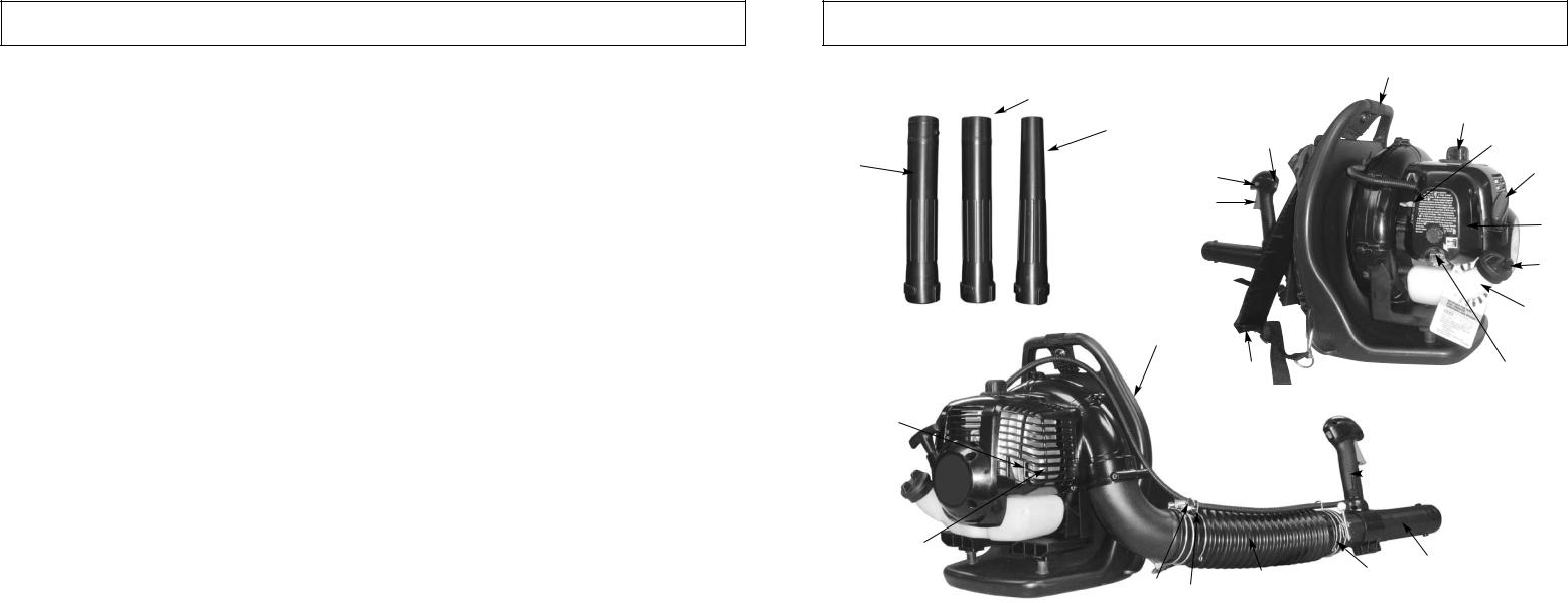
1-1. |
GENERAL IDENTIFICATION |
|
|
|
|
|
|
|
|
|
|
||||||
|
|
|
|
|
|
|
|
|
|
|
|
|
|||||
1. |
THROTTLE TRIGGER |
13. |
CONTROL HANDLE |
||||||||||||||
2. |
THROTTLE LOCK |
14. |
OPERATING TUBE |
|
|
|
|
|
|
||||||||
3. |
ON/OFF IGNITION SWITCH |
15. |
HOSE CLAMP |
|
|
|
|
|
|
||||||||
4. |
TOP ASSIST HANDLE |
16. |
FLEX TUBE |
|
|
|
|
|
|
||||||||
5. |
SPARK PLUG WIRE / SPARK PLUG |
17. |
THROTTLE LINKAGE |
||||||||||||||
6. |
CHOKE LEVER |
18. |
MUFFLER COVER |
|
|
|
|
|
|
||||||||
7. |
STARTER HANDLE |
19. |
SPARK ARRESTER SCREEN |
||||||||||||||
8. |
AIR CLEANER COVER |
20. |
VENTED BACK PAD |
||||||||||||||
9. |
FUEL CAP |
21. |
INTERMEDIATE TUBE |
||||||||||||||
10. |
FUEL TANK |
22. |
2-3/16” (56mm) NOZZLE |
||||||||||||||
11. |
PRIMER BULB |
23. |
1-9/16” (40mm) CONCENTRATOR NOZZLE |
||||||||||||||
12. |
HARNESS |
24. |
THROTTLE LINKAGE CLIPS |
||||||||||||||
3

|
1 - GENERAL INFORMATION |
|
|
1-2. SPECIFICATIONS |
|
ENGINE |
|
Engine Type . . . . . . . . . . . . . . . . . . . . . |
. . . . . . . . . . . . . . . . . . . . . . . . . . . . . . . . . . . . . . .Air-Cooled, 2-Cycle |
Displacement . . . . . . . . . . . . . . . . . . . . |
. . . . . . . . . . . . . . . . . . . . . . . . . . . . . . . . . . . . . . .(30 cc) (1.83 cu in.) |
Idle Speed RPM . . . . . . . . . . . . . . . . . . |
. . . . . . . . . . . . . . . . . . . . . . . . . . . . . . . . . . . . . . . 3,400 - 4,400 rpm |
Operating RPM . . . . . . . . . . . . . . . . . . |
. . . . . . . . . . . . . . . . . . . . . . . . . . . . . . . . . . . . . . .9,000 rpm |
Ignition Type . . . . . . . . . . . . . . . . . . . . . |
. . . . . . . . . . . . . . . . . . . . . . . . . . . . . . . . . . . . . . .Electronic |
Ignition Switch . . . . . . . . . . . . . . . . . . . |
. . . . . . . . . . . . . . . . . . . . . . . . . . . . . . . . . . . . . . .Rocker Switch |
Spark Plug Gap . . . . . . . . . . . . . . . . . . |
. . . . . . . . . . . . . . . . . . . . . . . . . . . . . . . . . . . . . . .0.025 in. (0.635 mm) |
Lubrication . . . . . . . . . . . . . . . . . . . . . . |
. . . . . . . . . . . . . . . . . . . . . . . . . . . . . . . . . . . . . . .Fuel/Oil Mixture |
Fuel/Oil Ratio . . . . . . . . . . . . . . . . . . . . |
. . . . . . . . . . . . . . . . . . . . . . . . . . . . . . . . . . . . . . .40:1 |
Carburetor . . . . . . . . . . . . . . . . . . . . . . |
. . . . . . . . . . . . . . . . . . . . . . . . . . . . . . . . . . . . . . .with primer |
Muffler . . . . . . . . . . . . . . . . . . . . . . . . . |
. . . . . . . . . . . . . . . . . . . . . . . . . . . . . . . . . . . . . . .Baffled with Guard |
Fuel Tank Capacity . . . . . . . . . . . . . . . . |
. . . . . . . . . . . . . . . . . . . . . . . . . . . . . . . . . . . . . . .18.5oz (550ml) |
BLOWER |
|
Throttle Control . . . . . . . . . . . . . . . . . . |
. . . . . . . . . . . . . . . . . . . . . . . . . . . . . . . . . . . . . . .Finger-Tip Trigger |
Blower Velocity . . . . . . . . . . . . . . . . . . . |
. . . . . . . . . . . . . . . . . . . . . . . . . . . . . . . . . . . . . . .up to 180 mph |
Blower Air Output . . . . . . . . . . . . . . . . . |
. . . . . . . . . . . . . . . . . . . . . . . . . . . . . . . . . . . . . . .up to 400 cfm |
Approximate Unit Weight (No fuel) . . |
. . . . . . . . . . . . . . . . . . . . . . . . . . . . . . . . . . . . . . .14.3 lbs |
4
2 - SAFETY PRECAUTIONS
2-1. WHAT TO DO
READ YOUR USER MANUAL AND ALL SUPPLEMENTS (IF ANY ENCLOSED) THOROUGHLY BEFORE OPERATING YOUR UNIT.
1.WEAR CLOSE FITTING, TOUGH WORK CLOTHING that will provide protection, such as long slacks or trousers, safety work shoes, heavy duty work gloves, hard hat, a safety face shield, or safety glasses for eye protection and a good grade of ear plugs or other sound barriers for hearing protection.
2.REFUEL IN A SAFE PLACE. Open fuel cap slowly to release any pressure which may have formed in fuel tank. Always wipe unit of fuel or oil spills before starting. To prevent a fire hazard, move at least 10 feet (3 meters) from fueling area before starting.
3.COMPLY WITH ALL FIRE PREVENTION REGULATIONS. COMPLIANCE WITH ALL LOCAL, STATE, OR FEDERAL LAWS IN THE UNITED STATES IS THE USER’S RESPONSIBILITY.Your unit comes with a spark arrester screen furnished in the user kit. Replacement spark arrester screen kits are available at your nearest McCulloch Authorized Service Center listed under “SAWS” in your Telephone Directory Yellow Pages.
4.TURN UNIT OFF before setting it down, and also before installing or removing attachments.
5.KEEP ALL SCREWS AND FASTENERS TIGHT and the unit in good operating condition. Never operate this equipment if it is improperly adjusted or not completely and securely assembled.
6.KEEP HANDLES DRY, clean and free of fuel mixture.
7.STORE EQUIPMENT AWAY FROM POSSIBLE IGNITION SOURCES, such as gas-powered water heaters, clothes dryers, or oil-fired furnaces, portable heaters, etc.
8.ALWAYS KEEP the engine free of debris build-up.
9.OPERATION OF EQUIPMENT should always be restricted to mature and properly instructed individuals.
10.ALL PERSONS WITH RESPIRATORY PROBLEMS and persons operating blower in very dusty environments, should wear a dust particle mask at all times. Paper dust masks are available at most paint and hardware stores.
2-2. WHAT NOT TO DO
1.DO NOT USE ANY OTHER FUEL than that recommended in your manual. Always follow
instructions in the Fuel and Lubrication section of this manual. Never use gasoline unless it is properly mixed with 2-cycle engine lubricant. Permanent damage to engine will result, voiding manufacturer’s warranty.
2.DO NOT SMOKE while refueling or operating equipment.
3.DO NOT OPERATE UNIT WITHOUT A MUFFLER and properly installed muffler shield.
4.DO NOT TOUCH or let your hands or body come in contact with a hot muffler or spark plug wire.
5.DUE TO THE DANGER of exhaust fumes, never operate blower in a confined or poorly ventilated area.
6.NEVER POINT BLOWER in the direction of people, animals, buildings, automobiles, or windows, etc.
7.DO NOT operate unit without inlet cover installed to prevent contact with impeller.
8.DO NOT set a hot engine down where flammable material is present.
9.DO NOT OPERATE UNIT FOR PROLONGED PERIODS. Rest periodically.
10.DO NOT OPERATE UNIT WHILE UNDER THE INFLUENCE OF ALCOHOL OR DRUGS.
11.DO NOT ADD, REMOVE OR ALTER ANY COMPONENTS OF THIS PRODUCT. Doing so could
cause personal injury and/or damage the unit voiding the manufacturer’s warranty.
12.DO NOT operate your unit near or around flammable liquids or gases whether in or out of doors. An explosion and/or fire may result.
13.DO NOT WEAR loose clothing, scarfs, neck chains, unconfined long hair, and the like. Doing so could cause injury associated with objects being drawn into the rotating parts.
14.DO NOT refuel a running engine or an engine that is hot.
5
2 - SAFETY PRECAUTIONS
2-3. INTERNATIONAL SYMBOLS
Use of these personal safety items is highly recommended to reduce the risk of accidental injury.
Minimum operating distance
Read the User Manual.
Pump the primer bulb 10 times.
6
3 - ASSEMBLY INSTRUCTIONS
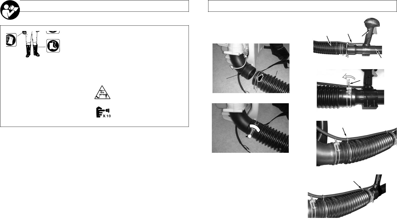
3-1. ATTACH FLEX TUBE
Put the hose clamp(C) on the flex tube before connecting |
|
|
|
|
|
|
|
|
|
|
|
the flex tube and the fan’s outlet tube together. |
|
|
|
|
|
|
|
|
|
|
|
Connect the flex tube (B) to the fan’s outlet tube (A) (Fig. |
|
|
|
|
|
|
|
|
|
|
|
|
|
|
D |
|
|
|
|
|
|
|
|
3-1A) with a hose clamp (C) (Fig. 4-1B) and tighten |
|
B |
|
|
|||||||
|
|
|
|
|
|
|
|
|
|
||
|
|
|
|
|
|
|
|
|
|
||
securely (Fig. 3-1B). |
|
|
|
|
|
F |
|
|
|
|
|
|
|
|
|
|
|
|
|
|
|||
|
|
|
|
180˚ |
|
|
|||||
|
|
|
E |
||||||||
|
|
|
|
|
|
|
|
|
|
|
|
|
|
|
|
|
|
|
|
|
|
|
|
|
|
|
|
3-2A |
|||||||
B |
|
|
|
|
|
|
|
|
|
|
|
|
|
|
|
|
|
|
|
|
|
|
|
|
|
|
|
|
|
|
|
||||
A |
|
|
|
|
|
|
G |
|
|||
|
|
|
|
|
|
|
|
|
|
|
|
3-1A
3-2B
THROTTLE LINKAGE CLIPS
C
3-1B
3-2. ATTACH OPERATING TUBE
NOTE: keep the throttle cable as straight as possible when connecting the blower tubes.
1.Place the unit on flat surface during assembly. Insure screw mechanism of clamp is positioned away from operator.
2.Put the hose clamp (C) on the flex tube and the operating tube before connecting them together.
3.Turn the throttle linkage mark (D) so it aligns with the throttle handle (F) (Fig.3-2A). Insert the operating tube (E) into the flex tube (B) (Fig. 3-2A) and then tighten securely with a hose clamp (G) (Fig. 3-2B).
4.Attached throttle linkage clips (# 24-know your blower) - to both ends of the flex tube to secure the throttle cable. ( Fig. 3-2D)
3-2C
THROTTLE LINKAGE CLIPS
3-2D
7
3 - ASSEMBLY INSTRUCTIONS
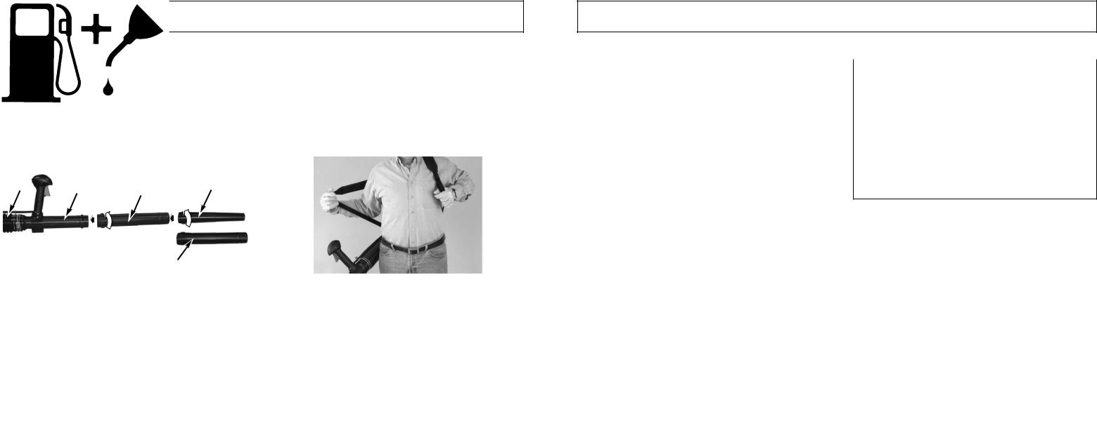
3-3. ATTACH INTERMEDIATE TUBE AND CONCENTRATOR NOZZLE
Connect the intermediate tube (H) and concentrator nozzle (I) or 56mm nozzle (J) (you can only use I nozzle at time). Push the tubes together and turn them clockwise so that they lock together (Fig. 3-3A). Use concentrator nozzle when you need more airflow in tight places: flower beds, under decks, etc.
3-4. ADJUST BACK PACK HARNESS AND CONTROL HANDLE
1.Place blower on your back by slipping arms through the shoulder straps as if you were putting on a jacket (Figure 3-4A).
2.Adjust backpack harness and control handle.
3.Once adjustments have been made, to the straps for user comfort, remove the blower from your back and place on level ground in an upright position.
B |
D |
H |
I |
|
|
||
|
|
|
1-9/16” (40mm) |
|
|
|
2-3/16” (56mm) |
|
|
|
J |
|
3-3A |
|
3-4A |
8
4 - FUEL AND LUBRICATION
4-1. FUEL
Use regular grade unleaded gasoline mixed with Genuine McCulloch 40:1 2-cycle engine oil for best results. Use mixing ratios in Section 4-3.
Never use straight gasoline in your unit. This will cause permanent engine damage and void the manufacturer’s warranty for that product. Never use a fuel mixture that
has been stored for over 90 days.
If 2-cycle lubricant other than Genuine McCulloch Custom Lubricant is to be used, it must be a premium grade oil for 2-cycle air cooled engines mixed at a 40:1 ratio. Do not use any 2-cycle oil product with a recommended mixing ratio of 100:1. If insufficient lubrication is the cause of engine damage, it voids the manufacturer’s
engine warranty for that occurrence.
4-2. MIXING FUEL
Mix fuel with Genuine McCulloch brand 2 cycle oil in an approved container. Use mixing table for correct ratio of fuel to oil. Shake container to ensure thorough mix.
 Lack of lubrication voids engine warranty.
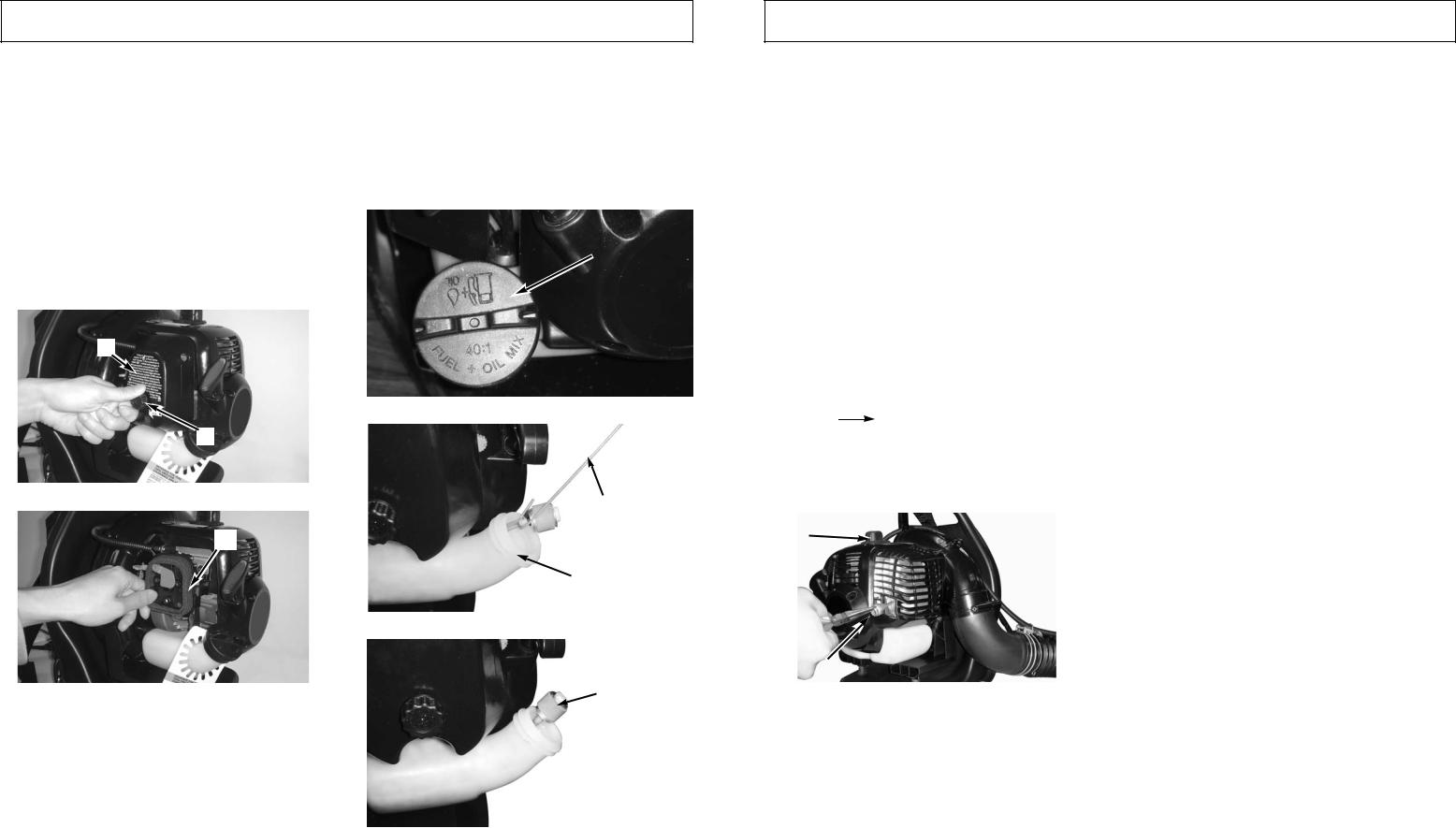
4-3.FUEL AND LUBRICATION SYMBOLS
FUEL MIXING TABLE
GASOLINE |
McCulloch 40:1 Ratio |
|||
Lubricant |
||||
|
|
|||
|
|
|
|
|
1 |
U.S. Gal. |
3.2 oz. |
95ml (cc) |
|
|
|
|
|
|
5 |
Liters |
4.3 oz. |
125ml (cc) |
|
|
|
|
||
1 lmp. Gal. |
4.3 oz. |
125ml (cc) |
||
|
|
|
|
|
|
Mixing |
40 Parts |
Gasoline to |
|
|
Procedure |
1 Part Lubricant |
||
|
|
|
|
|
1ml=1cc
4-4.RECOMMENDED FUELS
Some conventional gasolines are being blended with oxygenates such as alcohol or an ether compound to meet clean air standards. Your McCulloch engine is designed to operate on any gasoline intended for automotive use including oxygenated gasolines.
Gasoline and Oil
Mix 40:1
9

5 - STARTING/STOPPING INSTRUCTIONS
5-1. STARTING A COLD ENGINE
Fill fuel tank with proper gas and oil mixture. See FUEL AND LUBRICATION. Set unit upright on ground so that it rests on the back pack frame.
1.Pump primer bulb10 X by pressing up on the bulb (D). (Fig. 5-1B)
2.Your unit is designed with a 3 position choke: FULL CHOKE “  ”, PARTIAL CHOKE “
  ”, and RUN “
  ”. Move choke lever to FULL CHOKE “
  ” position. (Fig. 5-1A)
3.Set throttle lock (C): While holding trigger (B) at wide open position, press down and hold throttle lock (C). Release throttle trigger (B), then release throttle lock
(C).Throttle trigger (B) will now remain in the wide open position. Make sure ignition switch is in the ON
(I)position. (Fig. 5-1C)
NOTE: Easy Start power assist starting significantly reduces the pulling effort. Pull the starter cord slowly to about 3 1/2 feet, the power assist will turn over the engine with little resistence from the engine.
4.With the unit on the ground, hold the top assist handle and step on the bottom of the frame with foot. (Fig. 5- 1D)
5.Pull starter rope 4-6 times-if unit does not start move choke lever to “  ” position and pull 4-6 more times (Fig. 5-1E). Wait 10 sec. after unit starts then move
choke lever to “  ” position. (Fig. 5-1F)
6.Press trigger to run.
NOTE: If engine fails to start after repeated attempts, refer to Troubleshooting section.
NOTE: Always pull starter rope straight out. Pulling starter at an angle will cause rope to rub against the eyelet. This friction will cause the rope to fray and wear more quickly. Always hold starter handle when rope retracts. Never allow rope to snap back from extended position. This could cause rope to snag or fray and also damage the starter assembly.
5-1A
10
D
5-1B
C
A
B
5-1C
5-1D
5-1E
5-1F
5 - STARTING/STOPPING INSTRUCTIONS
IMPORTANT IDLING INFORMATION
In some cases due to operating conditions (altitude, temperature etc.) your blower may need a slight adjustment to the idle speed.
After warm up, If unit does not Idle after restarting 2 times, follow these steps to adjust idle.
1.Locate the idle adjustment screw (G) on the carburetor (Fig. 5-1G).
2.Using a Phillips or slotted screwdriver - turn screw 1/4 to 1/2 turn clockwise (to the right). Unit should then idle properly.
E 
5-1G
5-2. STOPPING THE ENGINE
Emergency Stopping Procedure. When it is necessary to stop blower engine immediately, DEPRESS the OFF “STOP” switch (A) until the engine stops completely (Figure 5-2).
Normal Stopping Method. For normal stopping, release trigger and allow engine to return to idle speed. Then DEPRESS the OFF “STOP ” switch (A) until the engine stops completely. (Figure 5-2)
5-3. STARTING A WARM ENGINE (Engine has been stopped for no more than 15-
20minutes).
1.Set throttle latch (see step 2 for starting a cold engine), pull starter rope briskly.
2.If engine does not start, or starts and then stops after 5 rope pulls, follow procedure “STARTING A COLD ENGINE”.
A
5-2
11

6 - OPERATING INSTRUCTIONS
6-1. BLOWER OPERATIONS
WARNING
Because of flying debris, always wear American National Standards Institute approved shielded safety glasses or
face shield when operating blower.
WARNING
Before using your blower, review Safety Precautions in your User Manual, and all regulations for operation of the unit.
These precautions and regulations are for your protection.
WARNING
DO NOT operate the blower with other people or animals in the immediate vicinity. Allow a minimum of 50 feet (15 meters) between operator and other people or animals.
1.Use the blower for trees, shrubs, flower beds, and hard-to-clean areas.
2.Use the unit around buildings and for other normal cleaning procedures.
3.Use the blower around walls, overhangs, fences, and screens.
4.We recommend that a face mask be worn when operating blower in dusty areas.
5.Stand away from the debris, at a distance that will easily allow you to control the direction of blown debris. Never blow debris in direction of bystanders.
6.To control velocity of airstream, blower can be operated at any speed between idle and full throttle. Experience with the unit will help you determine the amount of airflow necessary for each application.
7.Operate power equipment only at reasonable hours-- not early in the morning or late at night when people might be disturbed. Comply with times listed in local ordinances.
8.To reduce sound levels, limit the number of pieces of equipment used at any one time.
9.Operate power blowers at the lowest possible throttle speed to do the job.
10.Check your equipment before operation, especially the muffler, air intakes and air filters.
11.Use rakes and brooms to loosen debris before blowing.In dusty conditions, slightly dampen surfaces when water is available.
12.Conserve water by using power blowers instead of hoses for many lawn and garden applications, including areas such as gutters, screens, patios, grills, porches and gardens.
13.Watch out for children, pets, open windows or freshly washed cars, and blow debris safely away.
14.Use intermediate tube plus nozzle of your choice so the airstream can work close to the ground.
15.After using blowers and other equipment, CLEAN UP! Dispose of debris in trash receptacles.
12
6-2. OPERATION INSTRUCTIONS
1.Follow the instructions “STARTING A COLD ENGINE”.
2.Once unit is running, place unit on your back by slipping arms through the shoulder straps as if your were putting on a jacket (Fig. 6-2A).
3.When preparing to clear an area of debris, always position yourself so that you can control the direction debris will be blown .
4.The control handle (A, Fig. 6-2B) and the flexibility of the blower tube assembly will allow you to clear the most hard-to-reach areas .
5.The hand grip, throttle trigger, throttle lock and ignition on/off switch (B) are all mounted on a swivel handle that offers a wide range of operating positions and comfort (Fig. 6-2C).
6-2A
6-2B
5-5C
7 - MAINTENANCE INSTRUCTIONS
7-1. MAINTENANCE SCHEDULE
Perform these required maintenance procedures at the frequency stated in the table. These procedures should also be a part of any seasonal tune-up.
NOTE: Maintenance, replacement, or repair of the emission control devices and system may only be performed by McCulloch service dealer.
WARNING
To prevent serious injury, never perform maintenance or repairs with unit running. Always service and repair a cool unit. Disconnect the spark plug wire to ensure that the unit cannot start.
A good preventive maintenance program of regular inspection and care will increase life and improve performance of your blower. This maintenance checklist is a guide for such a program.
Cleaning, adjustment, and part replacement may be required, under certain conditions, at more frequent intervals than those indicated.
CUSTOMER RESPONSIBILITY
MAINTENANCE CHECKLIST |
|
HOURS OF |
|||
EACH USE |
OPERATION |
||||
|
|
||||
|
|
|
|
||
ITEM |
BEFORE EACH USE |
|
10 |
20 |
|
|
|
|
|
|
|
SCREW / NUTS / BOLTS |
INSPECT / TIGHTEN |
|
|
|
|
|
|
|
|
|
|
AIR FILTER |
CLEAN OR REPLACE |
|
|
|
|
|
|
|
|
|
|
FUEL FILTER |
REPLACE |
|
|
|
|
|
|
|
|
|
|
SPARK PLUG |
CLEAN / ADJUST / REPLACE |
|
|
|
|
|
|
|
|
|
|
SPARK ARRESTER SCREEN |
INSPECT |
|
|
|
|
|
|
|
|
||
REPLACE |
|
|
|
||
|
|
|
|||
|
|
|
|
|
|
FUEL HOUSES |
INSPECT |
|
|
|
|
|
|
|
|
||
REPLACE AS REQUIRED |
|
|
|
||
|
|
|
|||
|
|
|
|
|
|
VACUUM TUBES |
INSPECT / CLEAN |
|
|
|
|
|
|
|
|
|
|
*Recommended for Maintenance by a Authorized Service Center Technician. |
|
|
|
||
|
|
|
|
|
|
13
7 - MAINTENANCE INSTRUCTIONS
7-2. AIR FILTER
CAUTION
NEVER operate blower without the air filter. The air filter must be kept clean. If it becomes damaged, install a new filter.
TO CLEAN AIR FILTER:
1.Loosen knob (A) holding air filter cover in place, remove cover (B) and lift filter (C) from air box (Fig. 7- 2A & Fig. 7-2B).
2.Wash filter in soap and water. DO NOT USE GASO-
LINE!
3.Air dry filter.
4.Reinstall filter.
NOTE: Replace filter if frayed, torn, damaged or unable to be cleaned.
B
A
7-2A
C
7-2B
7-3. FUEL CAP / FUEL FILTER
CAUTION
Remove fuel from unit and store in approved container before starting this procedure. Open fuel cap slowly to release any pressure which may have formed in fuel tank.
FUEL FILTER:
1.Completely remove fuel cap (A) from fuel tank (B) to be able to remove fuel filter (C) from tank. Use a piece of wire (C) with a hook formed at the end to pull filter out of tank. (Fig. 7-3A & 7-3B)
2.Pull filter (D) off with a twisting motion. (Fig. 7-3C)
3.Replace fuel filter (D). (Fig. 7-3C)
NOTE: Never operate the blower without the fuel filter. Internal engine damage could result!
A
7-2A
C
B
7-2B
D
7-2C
14
7 - MAINTENANCE INSTRUCTIONS
7-4. IDLE ADJUSTMENT
The carburetor was pre-set at the factory for optimum performance. If further adjustments are necessary take your blower to McCulloch service dealer.
7-5. SPARK PLUG
1.To remove spark plug (B) (Fig. 7-5B) for cleaning or replacement: make sure engine is off, spark plug is cool, then grasp spark plug boot firmly and remove from spark plug. Remove spark plug with correct spark plug tool. Inspect, clean or replace as needed.
2.Spark plug gap = .025" (.635mm) (Fig. 7-5A).
3.Torque to 105 to 130 inch pounds (12 to 15 N•m). Connect spark plug boot.
4.If need replace spark plug with Champion RZ7C or equivalent.
.025" (.635mm)
Spark
Plug
7-5A
B
A
7-5B
7-6. SPARK ARRESTOR SCREEN / COLLAR ASSEMBLY
1.To replace spark arrestor screen/collar assembly (A) (Fig. 7-5B), use a needle nose pliers and pinch an edge of the collar. Pull out the whole spark arrestor screen assembly.
2.Use the needle nose pliers to push in a new spark arrestor screen assembly by opening the pliers slightly to press the inner surface of the assembly securely into place
15
7-7. STORAGE
Failure to follow these steps may cause varnish to form in the carburetor which can cause difficult starting or permanent damage following storage.
1.Perform all the general maintenance recommended in the Maintenance Section of your User Manual.
2.Clean exterior of engine and blower tubes.
3.Drain fuel from the fuel tank by running the unit dry or by removing the fuel cap and tipping the motor housing/fuel tank over and draining oil/fuel mixture into a container with the same 2-cycle fuel mixture.
4.After fuel is drained, start engine.
5.Run engine at idle until unit stops. This will purge the carburetor of fuel.
6.Allow engine to cool (approx. 5 minutes).
7.Using a spark plug wrench, remove the spark plug.
8.Pour 1 teaspoon of clean 2-cycle oil into the combustion chamber. Pull starter rope slowly several times to coat internal components. Replace spark plug.
9.Store unit in a cool, dry place away from any source of ignition such as an oil burner, water heater, etc.
7-8. REMOVING A UNIT FROM STORAGE
1.Remove spark plug.
2.Pull starter rope briskly to clear excess oil from combustion chamber.
3.Clean and gap spark plug or install a new spark plug with proper gap.
4.Prepare unit for operation.
5.Fill fuel tank with proper fuel / oil mixture. See Fuel and Lubrication Section.

8 - TROUBLESHOOTING THE ENGINE
PROBLEM
Unit won’t start or starts but will not run.
Unit starts, but engine has low power.
Engine hesitates.
No power under load.
Runs erratically.
Smokes excessively.
PROBABLE CAUSE
Incorrect starting procedures.
Incorrect carburetor mixture adjustment setting.
Fouled spark plug
Fuel filter plugged.
Incorrect lever position on choke.
Dirty spark arrester screen.
Dirty air filter.
Incorrect carburetor mixture adjustment setting.
Incorrect carburetor mixture adjustment setting.
Incorrectly gapped spark plug.
Incorrect carburetor mixture adjustment setting.
Incorrect fuel mixture.
CORRECTIVE ACTION
Follow instructions in the User Manual.
Have carburetor adjusted by an Authorized Service Center.
Clean / gap or replace plug.
Replace fuel filter.
Move to RUN position.
Replace spark arrester screen.
Remove, clean and reinstall filter.
Have carburetor adjusted by an Authorized Service Center.
Have carburetor adjusted by an Authorized Service Center.
Clean / gap or replace plug.
Have carburetor adjusted by an Authorized Service Center.
Use properly mixed fuel (40:1 mixture).
16
9 - ONE YEAR LIMITED WARRNATY
1.DURATION
The duration of the warranty for this McCulloch product is as follows: ONE (1) YEAR from date of original purchase only when used for personal, family, household, farm or ranch, purposes, provided the unit is not used for rental purposes; NINETY (90) DAYS from date of original purchase when used for commercial, professional, institutional or rental purposes. This warranty gives you specific legal rights. You may also have other rights which vary from state to state. MCCULLOCH CORPORATION HEREBY DISCLAIMS ALL IMPLIED WARRANTIES AFTER THE APPLICABLE EXPIRATION DATES OF THIS EXPRESS LIMITED WARRANTY. (Some states do not allow limitations on how long an implied warranty lasts, so the above limitations may not apply to you.)
2.WHO GIVES THIS WARRANTY
McCulloch U.S.A |
1-800-521-8559 |
10715 Springdale Avenue, Unit 2, Santa Fe Springs, CA 90670 USA
3.WHO RECEIVES THIS WARRANTY
A.The buyer (other than for purposes of resale) of the McCulloch Product.
B.Any person to whom such product is lawfully transferred within the duration of the implied or written warranty applicable to the product.
C.Any other person who is entitled by the terms of the warranty or under applicable state law to enforce against the Warrantor the obligation of the warranty.
(The above mentioned parties are hereinafter referred to as “User.”)
4.WHAT IS COVERED UNDER THIS WARRANTY
Any failure that occurs within the applicable duration of the warranty period that is the result of defects in materials or workmanship.
5.WHAT IS NOT COVERED UNDER THIS WARRANTY
A.Any incidental or consequential damages that may result from the failure or malfunction of the McCulloch product. (Some states do not allow the exclusion or limitation of incidental or consequential damages, so these limitations may not apply to you.)
B.Any failure that results from an accident, User abuse, neglect or failure to operate the product in accordance with the instructions provided in the User Manual(s) supplied with the product, or that results from improper servicing by an unauthorized repair facility.
C.Normal adjustments which are explained in the User Manual(s) provided with the product.
D.Any component(s) or accessories not sold or manufactured by the Warrantor.
E.Predelivery setup or assembly of units.
F.This warranty does not apply to accessories, normal maintenance or adjustment(s) of the product set forth in the User Manual(s).
6.RESPONSIBILITIES OF THE WARRANTOR UNDER THIS WARRANTY
A.Repair or replace components which have failed within the duration of the applicable warranty period at no cost to the User.
B.Ensure that the authorized repair station is reimbursed for parts and labor costs incurred due to performance of a warranty repair in accordance with established warranty policies and procedures.
7.RESPONSIBILITIES OF THE USER UNDER THIS WARRANTY
A.The User must deliver or ship the McCulloch product covered under this warranty to the dealer from whom it was originally purchased or to the nearest Authorized Service Center. Proof of purchase is required.
B.Freight costs, if any, will be borne by the user.
C.Use reasonable care in maintenance, operations and storage of the product as explained in the User Manual(s).
8.WHEN WARRANTOR WILL PERFORM OBLIGATION UNDER THIS WARRANTY
A.Repair of warrantable products will be scheduled according to the normal work flow at the servicing location, depending on the availability of replacement parts.
B.Repair time which exceeds ten (10) days from the time the product was delivered to the servicing agent will extend the warranty coverage by the number of days the product remains inoperable.
C.If User does not receive satisfactory results from local servicing outlet, User must contact McCulloch Corporation, by calling our toll-free telephone number.
17
 Loading...