


ELECTRIC DRYER
USE & CARE GUIDE
SÉCHEUSE ÉLECTRIQUE
GUIDE D’UTILISATION ET D’ENTRETIEN
FOR QUESTIONS ABOUT FEATURES, OPERATION/PERFORMANCE, |
SI TIENE PREGUNTAS RESPECTO A LAS CARACTERÍSTICAS, |
AU CANADA, POUR ASSISTANCE, INSTALLATION OU SERVICE, |
PARTS, ACCESSORIES OR SERVICE CALL: 1.800.688.9900 |
FUNCIONAMIENTO, RENDIMIENTO, PARTES, ACCESORIOS O |
COMPOSEZ LE : 1.800.807.6777 |
IN CANADA, CALL: 1.800.807.6777 |
SERVICIO TÉCNICO, LLAME AL: 1.800.688.9900 |
|
|
EN CANADÁ, LLAME AL: 1.800.807.6777 |
|
VISIT OUR WEBSITE AT WWW.MAYTAG.COM |
VISITE NUESTRO SITIO WEB EN |
OU VISITEZ NOTRE SITE INTERNET À |
IN CANADA, WWW.MAYTAG.CA |
WWW.MAYTAG.COM |
WWW.MAYTAG.CA |
|
EN CANADÁ, WWW.MAYTAG.CA |
|
W10057349A

TABLE OF CONTENTS
DRYER SAFETY...................................................................... |
3 |
INSTALLATION INSTRUCTIONS ......................................... |
4 |
Tools and Parts................................................................... |
4 |
Optional Pedestal............................................................... |
4 |
Location Requirements ...................................................... |
5 |
Electrical Requirements - U.S.A. Only................................ |
7 |
Electrical Requirements - Canada Only.............................. |
9 |
Electrical Connection - U.S.A. Only................................. |
10 |
Venting Requirements ...................................................... |
16 |
Plan Vent System.............................................................. |
17 |
Install Vent System ........................................................... |
19 |
Install Leveling Legs ......................................................... |
19 |
Connect Vent ................................................................... |
20 |
Level Dryer ...................................................................... |
20 |
Complete Installation ....................................................... |
20 |
DRYER USE.......................................................................... |
21 |
Starting Your Dryer........................................................... |
21 |
Stopping Your Dryer ........................................................ |
22 |
Pausing or Restarting........................................................ |
22 |
Control Lock .................................................................... |
23 |
Drying and Cycle Tips...................................................... |
23 |
Status Indicator................................................................. |
23 |
Cycles .............................................................................. |
24 |
Optional Features............................................................. |
25 |
Changing Cycles, Options and Modifiers ......................... |
26 |
Drying Rack Option ......................................................... |
26 |
DRYER CARE ...................................................................... |
27 |
Cleaning the Dryer Location ............................................ |
27 |
Cleaning the Lint Screen .................................................. |
27 |
Cleaning the Dryer Interior............................................... |
28 |
Removing Accumulated Lint ............................................ |
28 |
Vacation and Moving Care .............................................. |
28 |
Changing the Drum Light................................................. |
28 |
TROUBLESHOOTING........................................................ |
29 |
Dryer Operation............................................................... |
29 |
Dryer Results.................................................................... |
30 |
ASSISTANCE OR SERVICE................................................... |
31 |
In the U.S.A...................................................................... |
31 |
In Canada......................................................................... |
31 |
WARRANTY ........................................................................ |
32 |
2
ÍNDICE |
|
SÉCURITÉ DE LA SÉCHEUSE............................................... |
33 |
INSTRUCTIONS D'INSTALLATION ................................... |
34 |
Outillage et pièces ........................................................... |
34 |
Piédestal facultatif ............................................................ |
35 |
Exigences d'emplacement................................................ |
35 |
Spécifications électriques ................................................. |
37 |
Exigences concernant l'évacuation .................................. |
38 |
Planification du système d’évacuation ............................. |
40 |
Installation du système d’évacuation................................ |
41 |
Installation des pieds de nivellement................................ |
42 |
Raccordement du conduit d’évacuation........................... |
42 |
Mise à niveau de la sécheuse........................................... |
42 |
Achever l’installation........................................................ |
42 |
UTILISATION DE LA SÉCHEUSE......................................... |
43 |
Mise en marche de la sécheuse........................................ |
43 |
Arrêt de la sécheuse ......................................................... |
45 |
Pause ou remise en marche.............................................. |
45 |
Verrouillage des commandes ........................................... |
45 |
Conseils pour les programmes.......................................... |
45 |
Témoins lumineux............................................................ |
46 |
Programmes ..................................................................... |
46 |
Caractéristiques supplémentaires ..................................... |
47 |
Changement des programmes, options et modificateurs .. |
48 |
Grille de séchage ............................................................. |
48 |
ENTRETIEN DE LA SÉCHEUSE ........................................... |
50 |
Nettoyage de l'emplacement de |
|
la sécheuse...................................................................... |
50 |
Nettoyage du filtre à charpie ............................................ |
50 |
Nettoyage de l’intérieur de la sécheuse............................ |
50 |
Retrait de la charpie accumulée....................................... |
51 |
Précautions à prendre pour les vacances |
|
et avant un déménagement .............................................. |
51 |
Changement de l’ampoule d’éclairage |
|
du tambour....................................................................... |
51 |
DÉPANNAGE ...................................................................... |
52 |
Fonctionnement de la sécheuse ....................................... |
52 |
Résultats de la sécheuse ................................................... |
53 |
ASSISTANCE OU SERVICE.................................................. |
54 |
Aux États-Unis.................................................................. |
54 |
Au Canada ....................................................................... |
54 |
GARANTIE ....................................................................... |
55 |
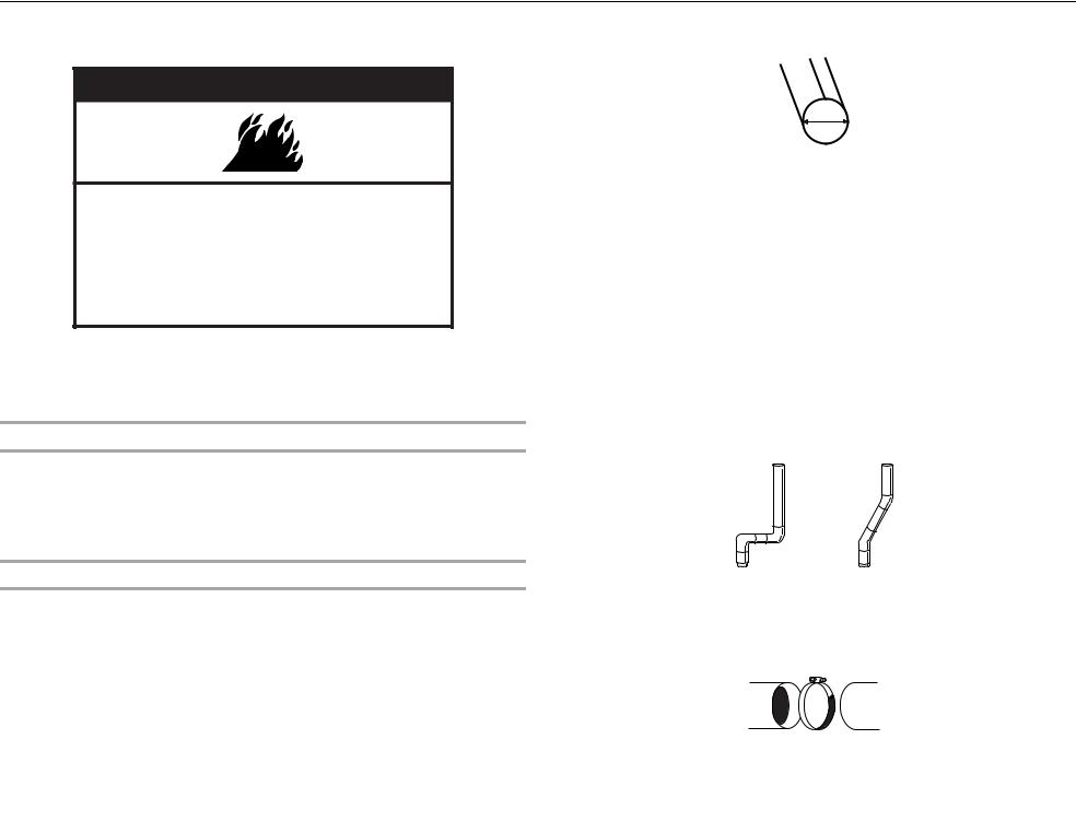
DRYER SAFETY
Your safety and the safety of others are very important.
We have provided many important safety messages in this manual and on your appliance. Always read and obey all safety messages.
This is the safety alert symbol.
This symbol alerts you to potential hazards that can kill or hurt you and others.
All safety messages will follow the safety alert symbol and either the word “DANGER” or “WARNING.” These words mean:
 DANGER
 WARNING
You can be killed or seriously injured if you don't immediately follow instructions.
You can be killed or seriously injured if you don't follow instructions.
All safety messages will tell you what the potential hazard is, tell you how to reduce the chance of injury, and tell you what can happen if the instructions are not followed.
IMPORTANT SAFETY INSTRUCTIONS
WARNING: To reduce the risk of fire, electric shock, or injury to persons when using the dryer, follow basic precautions, including the following:
■ Read all instructions before using the dryer. |
■ Do not repair or replace any part of the dryer or attempt |
|
■ Do not place items exposed to cooking oils in your dryer. |
any servicing unless specifically recommended in this |
|
Items contaminated with cooking oils may contribute to |
Use and Care Guide or in published user-repair |
|
a chemical reaction that could cause a load to catch fire. |
instructions that you understand and have the skills to |
|
■ Do not dry articles that have been previously cleaned in, |
carry out. |
|
■ Do not use fabric softeners or products to eliminate static |
||
washed in, soaked in, or spotted with gasoline, dry- |
||
unless recommended by the manufacturer of the fabric |
||
cleaning solvents, or other flammable or explosive |
||
softener or product. |
||
substances as they give off vapors that could ignite or |
||
■ Do not use heat to dry articles containing foam rubber or |
||
explode. |
||
■ Do not allow children to play on or in the dryer. Close |
similarly textured rubber-like materials. |
|
■ Clean lint screen before or after each load. |
||
supervision of children is necessary when the dryer is |
||
used near children. |
■ Keep area around the exhaust opening and adjacent |
|
■ Before the dryer is removed from service or discarded, |
surrounding areas free from the accumulation of lint, dust, |
|
remove the door to the drying compartment. |
and dirt. |
|
■ Do not reach into the dryer if the drum is moving. |
■ The interior of the dryer and exhaust vent should be |
|
■ Do not install or store the dryer where it will be exposed |
cleaned periodically by qualified service personnel. |
|
■ See installation instructions for grounding requirements. |
||
to the weather. |
||
■ Do not tamper with controls. |
|
SAVE THESE INSTRUCTIONS
3
INSTALLATION INSTRUCTIONS
Tools and Parts
Gather the required tools and parts before starting installation. Read and follow the instructions provided with any tools listed here.
Flat-blade screwdriver
#2 Phillips screwdriver
Adjustable wrench that opens to 1" (2.5 cm) or hex-head socket wrench (for adjusting dryer feet)
Wire stripper (direct wire installations)
Level
Vent clamps
Caulking gun and compound (for installing new exhaust vent)
Tin snips (new vent installations)
¼" nut driver (recommended)
Tape measure
Parts supplied
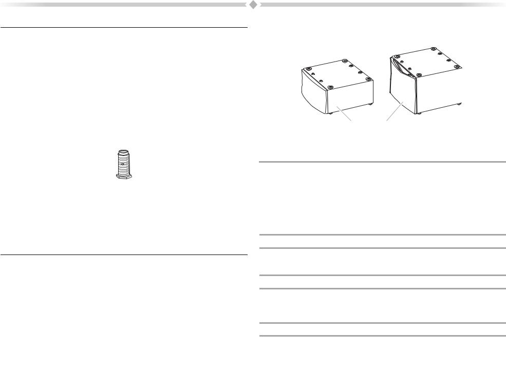
Remove parts packages from dryer drum. Check that all parts are included.
4 Leveling legs
NOTE: Do not use leveling legs if installing the dryer on a pedestal.
Parts needed
Check local codes. Check existing electrical supply and venting. See “Electrical Requirements” and “Venting Requirements” before purchasing parts.
Mobile home installations require metal exhaust system hardware available for purchase from the dealer from whom you purchased your dryer. For further information, please refer to the “Assistance or Service” section.
Optional Pedestal
Are you placing the dryer on a pedestal? You have the option of purchasing pedestals of different heights separately for this dryer. You may select a 10" (25.4 cm) or 15.5" (39.4 cm) pedestal with drawer. The pedestal will add to the total height of the dryer for a total height of approximately 48" (121.9 cm) or 53.5" (135.9 cm), respectively.
For a garage installation, you will need to place the 10" (25.4 cm) pedestal at least
9" (22.9 cm) above the floor. You will need to place the 15.5" (39.4 cm) pedestal at least 3.5" (8.9 cm) above the floor.
AB
A.10" (25.4 cm) pedestal
B.15.5" (39.4 cm) pedestal
The pedestals are available in several colors. To order, call the dealer from whom you purchased your dryer or refer to the “Assistance or Service” section.
Pedestal Height |
Color |
Part Number |
10" (25.4 cm) |
White |
MHP1000SQ |
|
|
|
15.5" (39.4 cm) |
White |
XHP1550VW |
|
|
|
15.5" (39.4 cm) |
Crimson |
XHP1550VF |
|
|
|
15.5" (39.4 cm) |
Evergreen |
XHP1550VP |
|
|
|
15.5" (39.4 cm) |
Oxide |
XHP1550VJ |
Stack Kit
Are you planning to stack your washer and dryer? To do so, you will need to purchase a Stack Kit. To order, call the dealer from whom you purchased your dryer or refer to the “Assistance or Service” section. Ask for Part Number 8212640.
Door Reversal Kit
Are you planing to reverse the door swing direction on your PERFORMANCE SERIES dryer? To do so, you will need to purchase a Door Reversal Kit.
To order, call the dealer from whom you purchased your dryer or refer to the “Assistance or Service” section. Ask for Part Number W10200372.
Backguard
If you are installing your PERFORMANCE SERIES washer and dryer and wish to avoid having loose items fall behind your machines, you may purchase a pair of washer/dryer backguards. These will reduce the chance of items falling behind the machines during operation.
To order, call the dealer from whom you purchased your dryer or refer to the “Assistance or Service” section. Ask for Part Number 8558694 (White).
4
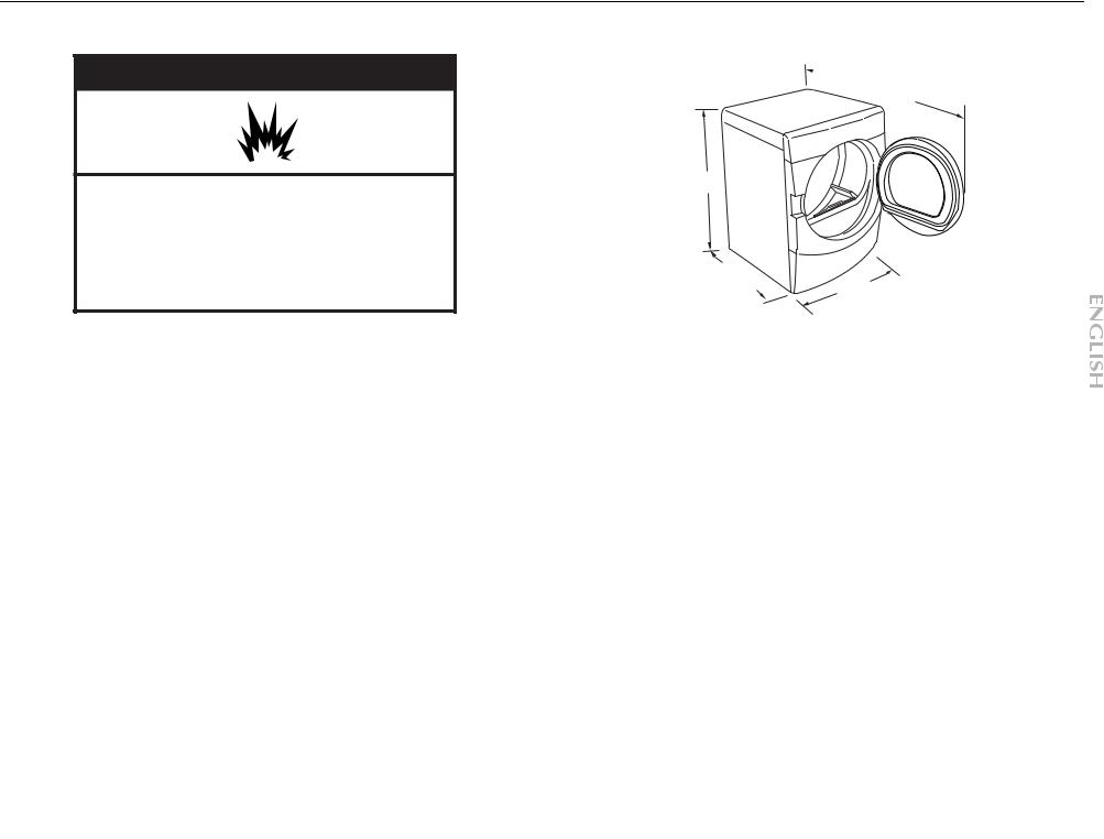
Location Requirements
 WARNING
Explosion Hazard
Keep flammable materials and vapors, such as gasoline, away from dryer.
Place dryer at least 18 inches (46 cm) above the floor for a garage installation.
Failure to do so can result in death, explosion, or fire.
You will need
A location that allows for proper exhaust installation. See “Venting Requirements.”
A separate 30-amp circuit.
If you are using a power supply cord, a grounded electrical outlet located within 2 ft (61 cm) of either side of the dryer. See “Electrical Requirements.”
A sturdy floor to support the total dryer weight of 200 lbs (90.7 kg). The combined weight of a companion appliance should also be considered.
A level floor with a maximum slope of 1" (2.5 cm) under entire dryer. If slope is greater than 1" (2.5 cm), install Extended Dryer Feet Kit, Part Number 279810. Clothes may not tumble properly and automatic sensor cycles may not operate correctly if dryer is not level.
For a garage installation, you will need to place the dryer at least 18" (46 cm) above the floor. If using a pedestal, you will need 18" (46 cm) to the bottom of the dryer.
Do not operate your dryer at temperatures below 45ºF (7ºC). At lower temperatures, the dryer might not shut off at the end of an automatic sensor cycle. This can result in longer drying times.
The dryer must not be installed or stored in an area where it will be exposed to water and/or weather.
Check code requirements. Some codes limit, or do not permit, installation of the dryer in garages, closets, mobile homes or sleeping quarters. Contact your local building inspector.
Installation clearances
The location must be large enough to allow the dryer door to open fully.
Dryer Dimensions
 51½" (130.81 cm)
38" (96.52 cm)
*31½"
(80 cm) 27"
(68.6 cm)
*Most installations require a minimum 5" (12.7 cm) clearance behind the dryer for the exhaust vent with elbow. See “Venting Requirements.”
Installation spacing for recessed area or closet installation
The following spacing dimensions are recommended for this dryer. This dryer has been tested for spacing of 0" (0 cm) clearance on the sides and rear. Recommended spacing should be considered for the following reasons:
Additional spacing should be considered for ease of installation and servicing.
Additional clearances might be required for wall, door and floor moldings.
Additional spacing should be considered on all sides of the dryer to reduce noise transfer.
For closet installation, with a door, minimum ventilation openings in the top and bottom of the door are required. Louvered doors with equivalent ventilation openings are acceptable.
Companion appliance spacing should also be considered.
5

Custom undercounter installation - Dryer only
0" (0 cm)
38" min. (96.52 cm)
1"* |
|
|
|
|
27" |
|
|
|
1"* |
(2.5 cm) |
|
(68.6 cm) |
|
|
(2.5 cm) |
||||
|
|
||||||||
*Required spacing
Closet installation - Dryer only
|
14" max.* |
48 in.2* |
|
|
(35.6 cm) |
||
|
|
|
(310 cm2) |
|
18" min.* |
|
|
|
(45.72 cm) |
|
|
|
|
|
24 in.2* |
|
|
|
(155 cm2) |
1"* |
31½" |
5"** |
|
(2.5 cm) |
(80 cm) (12.7 cm) |
|
|
|
A |
|
B |
A. Side view - closet or confined area
B. Closet door with vents
*Required spacing
**For side or bottom venting, 0" (0 cm) spacing is allowed.
3"* (7.6 cm)
 3"* (7.6 cm)
6
Recessed or closet installation - Dryer on pedestal
|
|
|
|
|
14" max.* |
|
|
|
|
|
(35.6 cm) |
|
|
|
|
18" min.* |
|
|
|
|
|
(45.72 cm) |
|
1" |
27" |
1" |
1"* |
31½" |
5"** |
(2.5 cm) |
(68.6 cm) |
(2.5 cm) |
(2.5 cm) |
(80 cm) |
(12.7 cm) |
|
A |
|
|
B |
|
A.Recessed area
B.Side view - closet or confined area
*Required spacing
**For side or bottom venting, 0" (0 cm) spacing is allowed.
Recommended installation spacing for cabinet installation
For cabinet installation, with a door, minimum ventilation openings in the top of the cabinet are required.
7"* (17.8 cm) |
7"* (17.8 cm) |
|
|
|
|
|
|
|
 9"*
9"*
 (22.9 cm)
|
|
31¹" |
1"* |
|
|
|
|
|
|
|
|
|
|
|
|
||
|
|
|
|
|
|
|
||
5"** |
1" |
27" |
1" |
|||||
|
(12.7 cm) |
(80.0 cm) (2.5 cm) (2.5 cm)(68.6 cm) (2.5 cm) |
||||||
*Required spacing
**For side or bottom venting, 0" (0 cm) spacing is allowed.
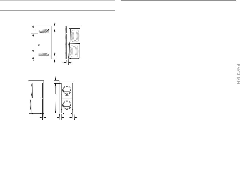
Recommended installation spacing for recessed or closet installation, with stacked washer and dryer
The dimensions shown are for the recommended spacing.
48 in.2 *
(310 cm2)
3"* (7.6 cm)
|
3"* (7.6 cm) |
24 in.2 * |
1"* (2.5 cm) |
(155 cm2) |
|
*Required spacing |
|
|
6"* (15.2 cm) |
76" (193 cm)
5"* |
|
|
|
1" |
|
|
|
27" |
|
1" |
|
|
|
|
|
||||||
(12.7 cm) |
|
|
(2.5 cm) |
|
|
(68.6 cm) |
(2.5 cm) |
|||
*Required spacing
Mobile home - Additional installation requirements
This dryer is suitable for mobile home installations. The installation must conform to the Manufactured Home Construction and Safety Standard, Title 24 CFR, Part 3280 (formerly the Federal Standard for Mobile Home Construction and Safety, Title 24, HUD Part 280) or Standard CAN/CSA-Z240 MH.
Mobile home installations require:
Metal exhaust system hardware, which is available for purchase from your dealer.
Special provisions must be made in mobile homes to introduce outside air into the dryer. The opening (such as a nearby window) should be at least twice as large as the dryer exhaust opening.
Electrical Requirements - U.S.A. Only
It is your responsibility
To contact a qualified electrical installer.
To be sure that the electrical connection is adequate and in conformance with the National Electrical Code, ANSI/NFPA 70-latest edition and all local codes and ordinances.
The National Electric Code requires a 4-wire power supply connection for homes built after 1996, dryer circuits involved in remodeling after 1996, and all mobile home installations.
A copy of the above code standards can be obtained from: National Fire Protection Association, One Batterymarch Park, Quincy, MA 02269.
To supply the required 3 or 4 wire, single phase, 120/240 volt, 60 Hz., AC only electrical supply (or 3 or 4 wire, 120/208 volt electrical supply, if specified on the serial/rating plate) on a separate 30-amp circuit, fused on both sides of the line. A time-delay fuse or circuit breaker is recommended. Connect to an individual branch circuit. Do not have a fuse in the neutral or grounding circuit.
Do not use an extension cord.
If codes permit and a separate ground wire is used, it is recommended that a qualified electrician determine that the ground path is adequate.
Electrical Connection
To properly install your dryer, you must determine the type of electrical connection you will be using and follow the instructions provided for it here.
This dryer is manufactured ready to install with a 3-wire electrical supply connection. The neutral ground conductor is permanently connected to the neutral conductor (white wire) within the dryer. If the dryer is installed with a 4-wire electrical supply connection, the neutral ground conductor must be removed from the external ground connector (green screw), and secured under the neutral terminal (center or white wire) of the terminal block. When the neutral ground conductor is secured under the neutral terminal (center or white wire) of the terminal block, the dryer cabinet is isolated from the neutral conductor.
If local codes do not permit the connection of a neutral ground wire to the neutral wire, see “Optional 3-wire connection” section.
A 4-wire power supply connection must be used when the appliance is installed in a location where grounding through the neutral conductor is prohibited. Grounding through the neutral is prohibited for (1) new branch-circuit installations, (2) mobile homes, (3) recreational vehicles, and (4) areas where local codes prohibit grounding through the neutral conductors.
7
If using a power supply cord: |
. |
Use a UL listed power supply cord kit marked for use with clothes dryers. The kit should contain:
A UL listed 30-amp power supply cord, rated 120/240 volt minimum. The cord should be type SRD or SRDT and be at least 4 ft (1.22 m) long. The wires that connect to the dryer must end in ring terminals or spade terminals with upturned ends.
A UL listed strain relief.
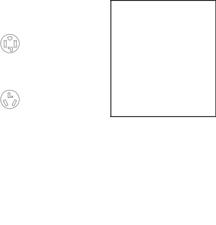
If your outlet looks like this:
4-wire receptacle (14-30R)
Then choose a 4-wire power supply cord with ring or spade terminals and UL listed strain relief. The 4-wire power supply cord, at least 4 ft (1.22 m) long, must have four 10-gauge copper wires and match a 4-wire receptacle of NEMA Type 14-30R. The ground wire (ground conductor) may be either green or bare. The neutral conductor must be identified by a white cover.
If your outlet looks like this:
3-wire receptacle (10-30R)
Then choose a 3-wire power supply cord with ring or spade terminals and UL listed strain relief. The 3-wire power supply cord, at least 4 ft (1.22 m) long, must have three 10-gauge copper wires and match a 3-wire receptacle of NEMA Type 10-30R.
If connecting by direct wire:
Power supply cable must match power supply (4-wire or 3-wire) and be:
Flexible armored cable or nonmetallic sheathed copper cable (with ground wire), protected with flexible metallic conduit. All current-carrying wires must be insulated.
10-gauge solid copper wire (do not use aluminum).
At least 5 ft (1.52 m) long.
8
GROUNDING INSTRUCTIONS
■ For a grounded, cord-connected dryer:
This dryer must be grounded. In the event of malfunction or breakdown, grounding will reduce the risk of electric shock by providing a path of least resistance for electric current.
This dryer uses a cord having an equipment-grounding conductor and a grounding plug. The plug must be plugged into an appropriate outlet that is properly installed and grounded in accordance with all local codes and ordinances.
■ For a permanently connected dryer:
This dryer must be connected to a grounded metal, permanent wiring system, or an equipment-grounding conductor must be run with the circuit conductors and connected to the equipment-grounding terminal or lead on the dryer.
WARNING: Improper connection of the equipmentgrounding conductor can result in a risk of electric shock. Check with a qualified electrician or service representative or personnel if you are in doubt as to whether the dryer is properly grounded. Do not modify the plug on the power supply cord: if it will not fit the outlet, have a proper outlet installed by a qualified electrician.
SAVE THESE INSTRUCTIONS
Electrical Requirements - Canada Only
 WARNING
Electrical Shock Hazard
Plug into a grounded 4 prong outlet.
Failure to do so can result in death or electrical shock.
It is your responsibility
To contact a qualified electrical installer.
To be sure that the electrical connection is adequate and in conformance with the Canadian Electrical Code, C22.1-latest edition and all local codes. A copy of the above codes standard may be obtained from: Canadian Standards Association, 178 Rexdale Blvd., Toronto, ON M9W 1R3 CANADA.
To supply the required 4 wire, single phase, 120/240 volt, 60 Hz., AC only electrical supply on a separate 30-amp circuit, fused on both sides of the line. A time-delay fuse or circuit breaker is recommended. Connect to an individual branch circuit.
This dryer is equipped with a CSA International Certified Power Cord intended to be plugged into a standard 14-30R wall receptacle. The cord is 5 ft (1.52 m) in length. Be sure wall receptacle is within reach of dryer’s final location.
If you are using a replacement power supply cord, it is recommended that you use Power Supply Cord Replacement Part Number 9831317. For further information, please reference the service numbers located in the “Assistance or Service” section.
GROUNDING INSTRUCTIONS
■ For a grounded, cord-connected dryer:
This dryer must be grounded. In the event of malfunction or breakdown, grounding will reduce the risk of electric shock by providing a path of least resistance for electric current.
This dryer is equipped with a cord having an equipmentgrounding conductor and a grounding plug. The plug must be plugged into an appropriate outlet that is properly installed and grounded in accordance with all local codes and ordinances.
WARNING: Improper connection of the equipmentgrounding conductor can result in a risk of electric shock. Check with a qualified electrician or service representative or personnel if you are in doubt as to whether the dryer is properly grounded. Do not modify the plug provided with the dryer: if it will not fit the outlet, have a proper outlet installed by a qualified electrician.
SAVE THESE INSTRUCTIONS
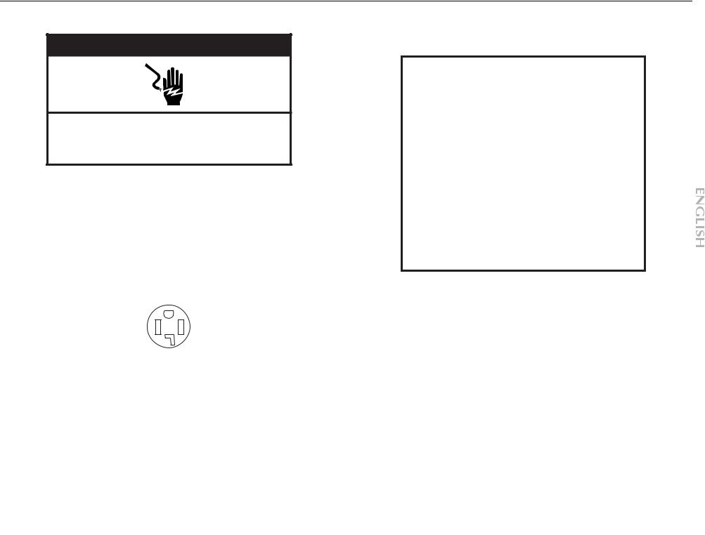
4-wire receptacle 14-30R
Do not use an extension cord.
9

Electrical Connection - U.S.A. Only
Power Supply Cord |
|
Direct Wire |
 WARNING
Fire Hazard
Use a new UL listed 30 amp power supply cord.
Use a UL listed strain relief.
Disconnect power before making electrical connections.
Connect neutral wire (white or center wire) to center terminal (silver).
Ground wire (green or bare wire) must be connected to green ground connector.
Connect remaining 2 supply wires to remaining 2 terminals (gold).
Securely tighten all electrical connections.
Failure to do so can result in death, fire, or electrical shock.
 WARNING
Fire Hazard
Use 10 gauge solid copper wire.
Use a UL listed strain relief.
Disconnect power before making electrical connections.
Connect neutral wire (white or center wire) to center terminal (silver).
Ground wire (green or bare wire) must be connected to green ground connector.
Connect remaining 2 supply wires to remaining 2 terminals (gold).
Securely tighten all electrical connections.
Failure to do so can result in death, fire, or electrical shock.
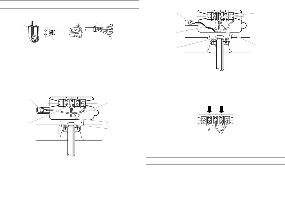
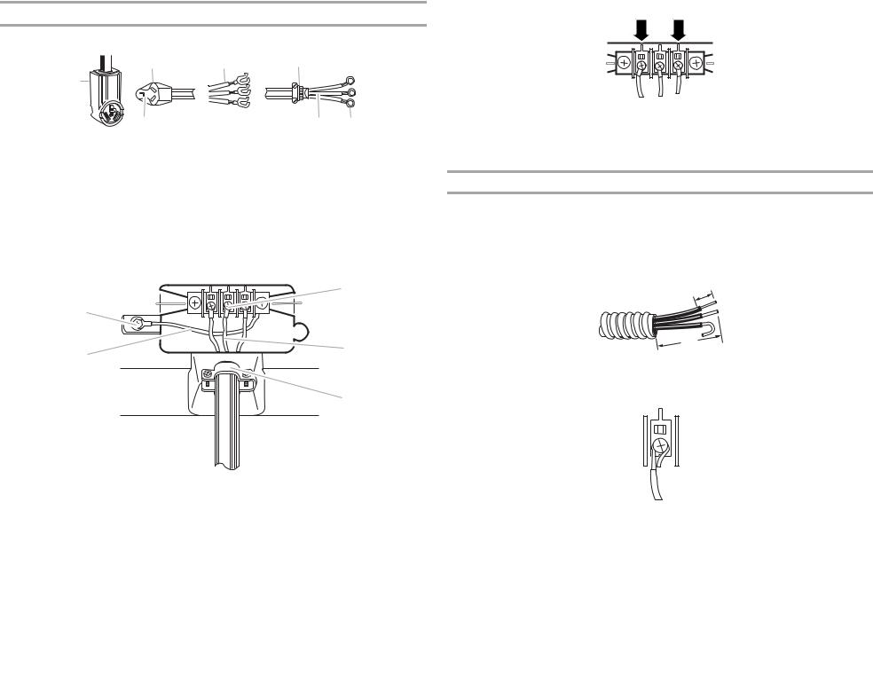
1.Disconnect power.
2.Remove the hold-down screw and terminal block cover.
C |
|
A. Neutral ground wire |
|
D |
B. External ground conductor screw |
||
|
|||
|
C. Center, silver-colored terminal |
||
|
|
||
|
|
block screw |
|
B |
|
D. Terminal block cover and hold- |
|
|
down screw |
||
|
|
A
3.Install strain relief.
Style 1: Power supply cord strain relief
Remove the screws from a 3/4" (1.9 cm) UL listed strain relief (UL marking on strain relief). Put the tabs of the two clamp sections into the hole below the terminal block opening so that one tab is pointing up and the other is pointing down, and hold in place. Tighten strain relief screws enough to hold the two clamp sections together.
 A
A
|
A. Strain relief tab pointing up |
B |
B. Hole below terminal block opening |
C. Clamp section |
|
C |
D. Strain relief tab pointing down |
D |
|
10
Put power supply cord through the strain relief. Be sure that the wire insulation on the power supply cord is inside the strain relief. The strain relief should have a tight fit with the dryer cabinet and be in a horizontal position. Do not further tighten strain relief screws at this point.
Style 2: Direct wire strain relief
Unscrew the removable conduit connector and any screws from a 3/4" (1.9 cm) UL listed strain relief (UL marking on strain relief). Put the threaded section of the strain relief through the hole below the terminal block opening. Reaching inside the terminal block opening, screw the removable conduit connector onto the strain relief threads.
 A
A
B
C
A.Removable conduit connector
B.Hole below terminal block opening
C.Strain relief threads
Put direct wire cable through the strain relief. The strain relief should have a tight fit with the dryer cabinet and be in a horizontal position. Tighten strain relief screw against the direct wire cable.
4.Now complete installation following instructions for your type of electrical connection: 4-wire (recommended)
3-wire (if 4-wire is not available)
Electrical Connection Options
If your home has: |
And you will be |
Go to Section |
|
connecting to: |
|
4-wire receptacle |
A UL listed, 120/240- |
4-wire connection: |
(NEMA Type 14-30R) |
volt minimum, |
Power supply cord |
|
30-amp, dryer power |
|
|
supply cord* |
|
4-wire direct |
A fused disconnect or |
4-wire connection: |
|
circuit breaker box* |
Direct Wire |
5" |
|
|
(12.7 cm) |
|
|
3-wire receptacle |
A UL listed, 120/240- |
3-wire connection: |
(NEMA type 10-30R) |
volt minimum, |
Power supply cord |
|
30-amp, dryer power |
|
|
supply cord* |
|
3-wire direct |
A fused disconnect or |
3-wire connection: |
|
circuit breaker box* |
Direct Wire |
3¹⁄" |
|
|
(8.9 cm) |
|
|
*If local codes do not permit the connection of a cabinet-ground conductor to the neutral wire, go to “Optional 3-wire connection” section.
11
4-wire connection: Power supply cord
IMPORTANT: A 4-wire connection is required for mobile homes and where local codes do not permit the use of 3-wire connections.
B F
A
C D E G
A.4-wire receptacle (NEMA type 14-30R)
B.4-prong plug
C.Ground prong
D.Neutral prong
E. Spade terminals with upturned ends F. ¾" (1.9 cm) UL listed strain relief
G.Ring terminals
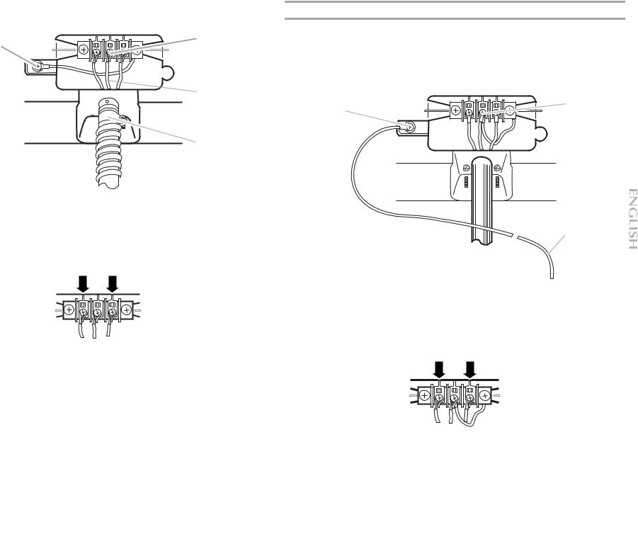
1.Remove center silver-colored terminal block screw.
2.Remove neutral ground wire from external ground conductor screw. Connect neutral ground wire and the neutral wire (white or center wire) of power supply cord under center, silver-colored terminal block screw. Tighten screw.
A
C
B |
D |
|
E |
A.External ground conductor screw - Dotted line shows position of NEUTRAL ground wire before being moved to center silvercolored terminal block screw.
B.Center silver-colored terminal block screw
C.Neutral ground wire
D.Neutral wire (white or center wire)
E.¾" (1.9 cm) UL listed strain relief
12
3.Connect ground wire (green or bare) of power supply cord to external ground conductor screw. Tighten screw.
A |
D |
 E
E
B
F
C
A.External ground conductor screw
B.Ground wire (green or bare) of power supply cord
C.¾" (1.9 cm) UL listed strain relief
D.Center silver-colored terminal block screw E. Neutral ground wire
F. Neutral wire (white or center wire)
4.Connect the other wires to outer terminal block screws. Tighten screws.
5.Tighten strain relief screws.
6.Insert tab of terminal block cover into slot of dryer rear panel. Secure cover with holddown screw.
7.You have completed your electrical connection. Now go to “Venting Requirements.”
4-wire connection: Direct wire
IMPORTANT: A 4-wire connection is required for mobile homes and where local codes do not permit the use of 3-wire connections.
Direct wire cable must have 5 ft (1.52 m) of extra length so dryer can be moved if needed.
Strip 5" (12.7 cm) of outer covering from end of cable, leaving bare ground wire at 5"
(12.7 cm). Cut 11/2" (3.8 cm) from 3 remaining wires. Strip insulation back 1" (2.5 cm). Shape ends of wires into a hook shape.
1"
.5cm) (2
3.Connect ground wire (green or bare) of direct wire cable to external ground conductor screw. Tighten screw.
A |
D |
|
5" |
|
(12.7 |
cm) |
|
|
When connecting to the terminal block, place the hooked end of the wire under the screw of the terminal block (hook facing right), squeeze hooked end together and tighten screw, as shown.
E
B
F
C
1.Remove center silver-colored terminal block screw.
2.Remove neutral ground wire from external ground conductor screw. Connect neutral ground wire and place the hooked end (hook facing right) of the neutral wire (white or center wire) of direct wire cable under the center screw of the terminal block. Squeeze hooked ends together. Tighten screw.
B
A
C
D
 E
E
A.External ground conductor screw - Dotted line shows position of NEUTRAL ground wire before being moved to center silver-colored terminal block screw.
B.Center silver-colored terminal block screw
C.Neutral ground wire
D.Neutral wire (white or center wire)
E.¾" (1.9 cm) UL listed strain relief
A.External ground conductor screw
B.Ground wire (green or bare) of power supply cable
C.¾" (1.9 cm) UL listed strain relief
D.Center silver-colored terminal block screw E. Neutral ground wire
F. Neutral wire (white or center wire)
4.Place the hooked ends of the other direct wire cable wires under the outer terminal block screws (hooks facing right). Squeeze hooked ends together. Tighten screws.
5.Tighten strain relief screw.
6.Insert tab of terminal block cover into slot of dryer rear panel. Secure cover with holddown screw.
7.You have completed your electrical connection. Now go to “Venting Requirements.”
13
3-wire connection: Power supply cord
Use where local codes permit connecting cabinet-ground conductor to neutral wire.
B D E
A
C G F
A.3-wire receptacle (NEMA type 10-30R)
B.3-wire plug
C.Neutral prong
D.Spade terminals with up turned ends E. ¾" (1.9 cm) UL listed strain relief
F. Ring terminals
G.Neutral (white or center wire)
1.Loosen or remove center silver-colored terminal block screw.
2.Connect neutral wire (white or center wire) of power supply cord to the center, silvercolored terminal screw of the terminal block. Tighten screw.
|
C |
A |
|
B |
D |
|
|
|
E |
3. Connect the other wires to outer terminal block screws. Tighten screws.
4.Tighten strain relief screws.
5.Insert tab of terminal block cover into slot of dryer rear panel. Secure cover with holddown screw.
6.You have completed your electrical connection. Now go to “Venting Requirements.”
3-wire connection: Direct wire
Use where local codes permit connecting cabinet-ground conductor to neutral wire.
Direct wire cable must have 5 ft (1.52 m) of extra length so dryer can be moved if needed.
Strip 31/2" (8.9 cm) of outer covering from end of cable. Strip insulation back 1" (2.5 cm). If using 3-wire cable with ground wire, cut bare wire even with outer covering. Shape ends of wires into a hook shape.
1" (2.5cm)
3¹⁄" (8.9 cm)
When connecting to the terminal block, place the hooked end of the wire under the screw of the terminal block (hook facing right), squeeze hooked end together and tighten screw, as shown.
A.External ground conductor screw
B.Neutral ground wire
C.Center silver-colored terminal block screw
D.Neutral wire (white or center wire)
E.¾" (1.9 cm) UL listed strain relief
1. Loosen or remove center silver-colored terminal block screw.
14
2.Place the hooked end of the neutral wire (white or center wire) of direct wire cable under the center screw of terminal block (hook facing right). Squeeze hooked end together. Tighten screw.
C
A
B 
 D
D
E
A.External ground conductor screw
B.Neutral ground wire
C.Center silver-colored terminal block screw
D.Neutral wire (white or center wire)
E.¾" (1.9 cm) UL listed strain relief
3.Place the hooked ends of the other direct wire cable wires under the outer terminal block screws (hooks facing right). Squeeze hooked ends together. Tighten screws.
4.Tighten strain relief screw.
5.Insert tab of terminal block cover into slot of dryer rear panel. Secure cover with holddown screw.
6.You have completed your electrical connection. Now go to “Venting Requirements.”
Optional 3-wire connection
Use for direct wire or power supply cord where local codes do not permit connecting cabinet-ground conductor to neutral wire.
1.Remove center silver-colored terminal block screw.
2.Remove neutral ground wire from external ground conductor screw. Connect neutral ground wire and the neutral wire (white or center wire) of power supply cord/cable under center, silver-colored terminal block screw. Tighten screw.
B
A
 C
C
 D
D
 E
E
F
A.External ground conductor screw
B.Center silver-colored terminal block screw
C.Neutral ground wire
D.Neutral wire (white or center wire) E. ¾" (1.9 cm) UL listed strain relief
F. Grounding path determined by a qualified electrician
3.Connect the other wires to outer terminal block screws. Tighten screws.
4.Tighten strain relief screws.
5.Connect a separate copper ground wire from the external ground conductor screw to an adequate ground.
6.Insert tab of terminal block cover into slot of dryer rear panel. Secure cover with holddown screw.
15
Venting Requirements
4" (10.2 cm) heavy metal exhaust vent and clamps must be used.
 WARNING
Fire Hazard
Use a heavy metal vent.
Do not use a plastic vent.
Do not use a metal foil vent.
Failure to follow these instructions can result in death or fire.
WARNING: To reduce the risk of fire, this dryer MUST BE EXHAUSTED OUTDOORS. IMPORTANT: Observe all governing codes and ordinances.
The dryer exhaust must not be connected into any gas vent, chimney, wall, ceiling or a concealed space of a building.
If using an existing vent system
Clean lint from the entire length of the system and make sure exhaust hood is not plugged with lint.
Replace any plastic or metal foil vent with rigid or flexible heavy metal vent.
Review vent system chart. Modify existing vent system if necessary to achieve the best drying performance.
If this is a new vent system
Vent material
Use a heavy metal vent. Do not use plastic or metal foil vent.
4"
10.2 cm
4" (10.2 cm) heavy metal exhaust vent
Vent products can be purchased from your dealer or by calling Maytag Services. For more information, see the “Assistance or Service” section.
Rigid metal vent
For best drying performance, rigid metal vents are recommended.
Rigid metal vent is recommended to avoid crushing and kinking.
Flexible metal vent
Flexible metal vents are acceptable only if accessible for cleaning.
Flexible metal vent must be fully extended and supported when the dryer is in its final location.
Remove excess flexible metal vent to avoid sagging and kinking that may result in reduced airflow and poor performance.
Do not install flexible metal vent in enclosed walls, ceilings or floors.
Elbows
45° elbows provide better airflow than 90° elbows.
Good |
Better |
Clamps
Use clamps to seal all joints.
Exhaust vent must not be connected or secured with screws or other fastening devices that extend into the interior of the duct. Do not use duct tape.
Clamp
16
Exhaust
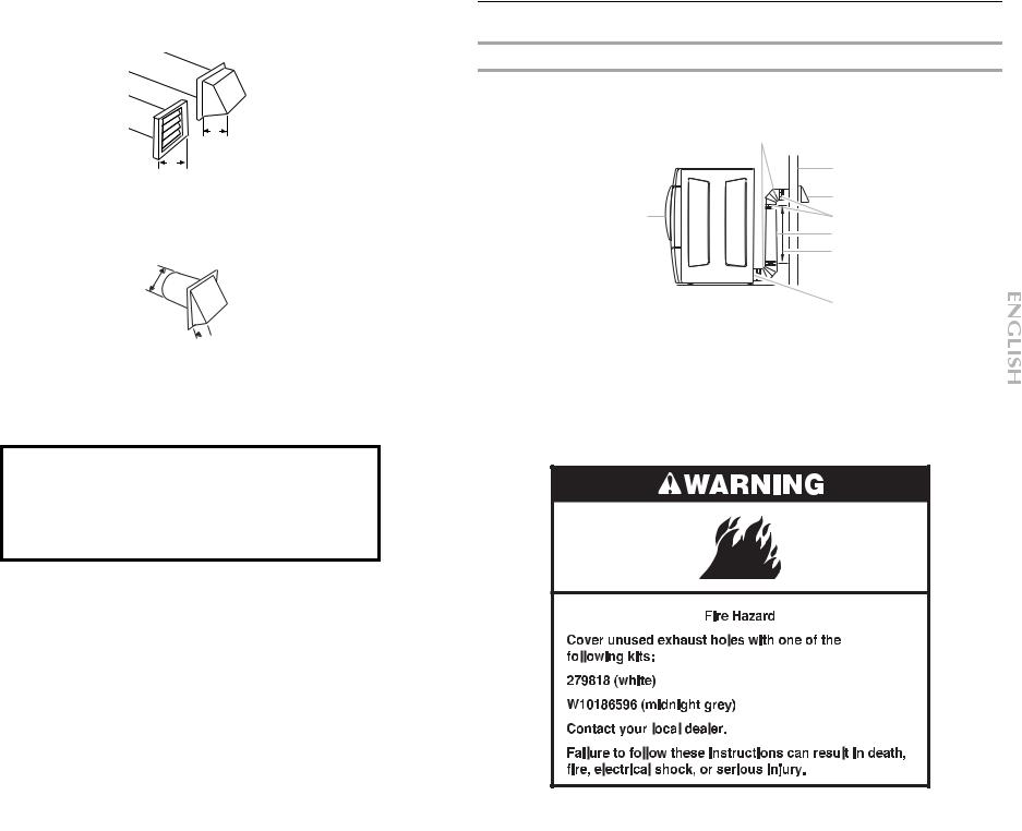
Recommended hood styles are shown here.
B
A
4" (10.2 cm)
4" (10.2 cm)
A.Louvered hood style
B.Box hood style
The angled hood style (shown here) is acceptable.
4" (10.2 cm)
 2½" (6.4 cm)
An exhaust hood should cap the vent to keep rodents and insects from entering the home.
Exhaust hood must be at least 12" (30.5 cm) from the ground or any object that may be in the path of the exhaust (such as flowers, rocks or bushes, snow line, etc.).
Do not use an exhaust hood with a magnetic latch.
Improper venting can cause moisture and lint to collect indoors, which may result in:
 Moisture damage to woodwork, furniture, paint, wallpaper, carpets, etc.
 Housecleaning problems and health problems.
Plan Vent System
Choose your exhaust installation type
Recommended exhaust installations
Typical installations vent the dryer from the rear of the dryer. Other installations are possible.
|
B |
|
C |
|
D |
A |
E |
|
F |
|
G |
|
H |
A. Dryer |
E. Clamps |
B. Elbow |
F. Rigid metal or flexible metal vent |
C. Wall |
G. Vent length necessary to connect elbows |
D. Exhaust hood |
H. Exhaust outlet |
Optional exhaust installations
This dryer can be converted to exhaust out the right side, left side or through the bottom. If you prefer, you may contact your local dealer to have the dryer converted
17
 Loading...