


Maytag HRE41240S, HRE11250T, HRE41250T, HRE41250S, HRE11282T User Manual
...
Series Twelve
ELECTRIC
WATER HEATER
USER’S GUIDE
FOR POTABLE WATER
HEATING ONLY
NOT SUITABLE FOR
SPACE HEATING
Model Numbers
HRE11240S
HRE41240S
HRE11250S
HRE41250S
HRE11250T
HRE41250T
HRE11282T
HRE41282T
LISTED
GAMA certification applies to all residential electric water heaters with capacities of 20 to 120 gallons. Input rating of 12 kW or less at a voltage no greater than 250V.
SAVETHISMANUALFORFUTUREREFERENCE.
|
www.maytagwaterheaters.com |
66001864 |
PRINTED IN THE U.S.A 1204 |
PART NO. 184743-001 |
1
SAFE INSTALLATION, USE AND SERVICE
Your safety and the safety of others is extremely important in the installation, use and servicing of this water heater.
Many safety-related messages and instructions have been provided in this manual and on your own water heater to warn you and others of a potential injury hazard. Read and obey all safety messages and instructions throughout this manual. It is very important that the meaning of each safety message is understood by you and others who install, use or service this water heater.
This is the safety alert symbol. It is used to alert you to potential personal injury hazards. Obey all safety messages that follow this symbol to avoid possible injury or death.
|
|
|
|
DANGER |
indicates |
an |
imminently |
|
|
DANGER |
|
||||
|
|
|
|||||
|
|
|
hazardous situation which, if not avoided, |
||||
|
|
|
|
could result in death or injury. |
|||
|
|
|
|
||||
|
|
|
|
||||
|
|
|
|
|
|
|
|
|
|
|
|
WARNING |
indicates |
a |
potentially |
|
|
WARNING |
|
||||
|
|
|
|||||
|
|
|
hazardous situation which, if not avoided, |
||||
|
|
|
|
could result in death or injury. |
|||
|
|
|
|
||||
|
|
|
|
|
|
|
|
|
|
|
|
CAUTION |
indicates |
a |
potentially |
|
|
CAUTION |
|
||||
|
|
|
|||||
|
|
|
hazardous situation which, if not avoided, |
||||
|
|
|
may result in minor or moderate injury. |
||||
|
|
|
|
||||
|
|
|
|
|
|
|
|
|
|
|
|
CAUTION used without the safety alert |
|||
|
|
|
|
||||
|
CAUTION |
|
symbol indicates a potentially hazardous |
||||
|
|
situation which, if not avoided, could |
|||||
|
|
|
|
result in property damage. |
|
||
|
|
|
|
|
|||
|
|
|
|
|
|
|
|
All safety messages will generally tell you about the type of hazard, what can happen if you do not follow the safety message and how to avoid the risk of injury.
IMPORTANT DEFINITIONS
•Maytag Customer Service Center: The Maytag Customer Service Center has the ability equivalent to a licensed tradesman in the fields of plumbing and electrical work including a thorough understanding of the requirements of the National Electric Code as it relates to the installation of electric water heaters. The Service Center also has a thorough understanding of this instruction manual, and is able to perform repairs strictly in accordance with the service guidelines provided by the manufacturer.
2
GENERAL SAFETY
3

TABLE OF CONTENTS |
|
SAFE INSTALLATION, USE AND SERVICE ........................................................................................................................................ |
2 |
GENERAL SAFETY ............................................................................................................................................................................. |
3 |
TABLE OF CONTENTS ....................................................................................................................................................................... |
4 |
CUSTOMER INFORMATION ............................................................................................................................................................... |
5 |
PRODUCT SPECIFICATIONS ............................................................................................................................................................ |
5 |
ACCESSORIES AND TOOLS NEEDED ............................................................................................................................................. |
6 |
Accessories ................................................................................................................................................................................. |
6 |
Tools ............................................................................................................................................................................................ |
6 |
INSTALLATION INSTRUCTIONS ................................................................................................................................................... |
7-16 |
Removing the Old Water Heater .............................................................................................................................................. |
7,8 |
Locating the New Water Heater .................................................................................................................................................. |
8 |
Insulation Blankets ...................................................................................................................................................................... |
8 |
Typical Installation .................................................................................................................................................................... |
8,9 |
The Convertible Lower Element .................................................................................................................................................. |
9 |
Water Piping .............................................................................................................................................................................. |
10 |
T & P Valve and Pipe Insulation ............................................................................................................................................ |
10,11 |
Temperature-Pressure Relief Valve ..................................................................................................................................... |
11,12 |
Filling the Water Heater ............................................................................................................................................................. |
12 |
Converting the Lower Element ............................................................................................................................................ |
12-14 |
Wiring .................................................................................................................................................................................... |
14,15 |
Wiring Diagrams ....................................................................................................................................................................... |
16 |
SERVICE AND MAINTENANCE .................................................................................................................................................. |
17-22 |
Temperature Regulation ........................................................................................................................................................... |
17 |
Thermostat ................................................................................................................................................................................ |
17 |
Temperature Settings ................................................................................................................................................................ |
17 |
Thermostat Adjustment ........................................................................................................................................................ |
17,18 |
Anode Rod Inspection ............................................................................................................................................................... |
18 |
Temperature-Pressure Relief Valve Operation ......................................................................................................................... |
18 |
Draining ................................................................................................................................................................................ |
18,19 |
Thermostat Removal/Replacement .......................................................................................................................................... |
19 |
Element Cleaning/Replacement ......................................................................................................................................... |
19-22 |
Drain Valve Washer Replacement ............................................................................................................................................ |
22 |
Service ....................................................................................................................................................................................... |
22 |
TROUBLESHOOTING GUIDE .................................................................................................................................................... |
22-25 |
Start Up Conditions ................................................................................................................................................................... |
22 |
Thermal Expansion ............................................................................................................................................................ |
22 |
Strange Sounds ................................................................................................................................................................. |
22 |
Operational Conditions ........................................................................................................................................................ |
23,24 |
Smelly Water ....................................................................................................................................................................... |
23 |
“Air” in Hot Water Faucets .................................................................................................................................................. |
23 |
Rumbling Noise .................................................................................................................................................................. |
23 |
High Temperature Shut Off System ............................................................................................................................... |
23,24 |
Not Enough or No Hot Water .............................................................................................................................................. |
24 |
Water Is Too Hot .................................................................................................................................................................. |
24 |
Leakage Checkpoints .......................................................................................................................................................... |
24,25 |
REPAIR PARTS LIST .................................................................................................................................................................. |
25-27 |
WARRANTY ...................................................................................................................................................................................... |
28 |
4

CUSTOMER INFORMATION
Thank You for purchasing a Maytag water heater. Properly installed and maintained, it should give you years of trouble free service. It is strongly suggested that this new water heater be professionally installed, call Maytag Customer Service at 1-800-788-8899 for recommended installers.
Abbreviations Found In This Instruction Manual:
UL – Underwriters Laboratories, Inc.
NEC – National Electrical Code
ANSI – American National Standards Institute
•Read the “General Safety” section, page 3 of this manual first and then the entire manual carefully. If you don’t follow the safety rules, the water heater will not operate properly. It could cause DEATH, SERIOUS BODILY INJURY AND/OR PROPERTY DAMAGE.
This manual contains instructions for the installation, operation, and maintenance of this electric water heater. It also contains warnings throughout the manual that you must read and be aware of. All warnings and all instructions are essential to the proper operation of the water heater and your safety. Since we cannot put everything on the first few pages, READ THIS ENTIRE MANUALBEFOREATTEMPTING TO INSTALL OR OPERATE THE WATER HEATER.
•The installation must conform with the instructions in this manual; electric company rules; and Local Codes, or in the
absence of Local Codes, with the current edition of the NEC - National Electrical Code NFPA 70. This publication is available from your local government or public library or electric company or by writing Underwriters Laboratories Inc., 333 Pfingsten Road, Northbrook, IL 60062.
•If after reading this manual you have any questions or do not understand any portion of the instructions, call Maytag Customer Service at 1-800-788-8899 for an authorized servicer.
•Carefully plan the place where you are going to put the water heater. Correct electrical wiring and connections are very important in preventing death from possible electrical shock and fires.
Examine the location to ensure the water heater complies with the “Locating the New Water Heater” section.
•For California installation this water heater must be braced, anchored, or strapped to avoid falling or moving during an earthquake. See instructions for correct installation procedures. Instructions may be obtained from the California office of the State Architect, 400 P Street, Sacramento, CA 95814.
•Massachusetts Code requires this water heater to be installed in accordance with Massachusetts 248-CMR 2.00: State Plumbing Code and 248-CMR 5.00. In the Commonwealth of Massachusetts, this product must be installed by a licensed plumber or gasfitter.
PRODUCT SPECIFICATIONS
|
|
|
|
RECOVERY RATE |
|
|
ELEMENT |
|
|
MAXIMUM |
||
|
|
|
|
IN GALLONS |
|
|
|
|
FUSEOR |
|||
|
TANK |
DIMENSIONS |
PERHOUR |
|
|
WATTAGE |
|
|
CIRCUIT |
|||
|
CAPACITY |
IN INCHES |
@ 90°F RISE |
|
@240 VOLTS |
MINIMUM |
BREAKER |
|||||
MODEL |
|
|
|
|
|
|
|
|
LOWER |
WIRE SIZE |
SIZE |
|
NUMBER |
GALS |
DIA. |
HEIGHT |
UPPER |
LOWER |
UPPER |
|
(GAUGE) |
(AMPS) |
|||
HRE11240S |
40 |
22.5 |
47 |
17.3 |
17.3 |
25 |
3800 |
|
3800 |
5500 |
12 |
20 |
HRE41240S |
40 |
22.5 |
47 |
17.3 |
17.3 |
25 |
3800 |
|
3800 |
5500 |
10 |
30 |
HRE11250S |
50 |
24 |
50 |
17.3 |
17.3 |
25 |
3800 |
|
3800 |
5500 |
12 |
20 |
HRE41250S |
50 |
24 |
50 |
17.3 |
17.3 |
25 |
3800 |
|
3800 |
5500 |
10 |
30 |
HRE11250T |
50 |
22.5 |
57 |
17.3 |
17.3 |
25 |
3800 |
|
3800 |
5500 |
12 |
20 |
HRE41250T |
50 |
22.5 |
57 |
17.3 |
17.3 |
25 |
3800 |
|
3800 |
5500 |
10 |
30 |
HRE11282T |
80 |
26 |
62 |
17.3 |
17.3 |
25 |
3800 |
|
3800 |
5500 |
12 |
20 |
HRE41282T |
80 |
26 |
62 |
17.3 |
17.3 |
25 |
3800 |
|
3800 |
5500 |
10 |
30 |
**Wiring size based on standard 60°C copper wire. If distance from fuse box to water heater is more than 90 feet, refer to your local electrical code.
5
ACCESSORIES AND TOOLS NEEDED
Accessories
To simplify the installation Maytag has available the installation parts shown below. You may or may not need all of these accessories depending on your type of installation. Call Maytag Customer Service at 1-800-788-8899 for an authorized installer.
EXPANSION TANKS FOR THERMAL EXPANSION CONDITIONS AVAILABLE IN 2 GALLONS (7.6 LITERS), Part No. 66001013 AND 5 GALLONS (18.9 LITERS), Part No. 66001014 CAPACITY.
DRAIN PANS AVAILABLE IN 22” (559 mm) DIAMETER (PART NO. 66001011) FOR WATER HEATERS HAVING A DIAMETER 20” (508 mm) OR LESS, 24” (610mm) DIAMETER (PART NO. 66001105) FOR WATER HEATERS HAVING A DIAMETER 22” (559 mm) OR LESS AND 28” (711 mm) DIAMETER (PART NO. 66001012) FOR WATER HEATERS HAVING A DIAMETER 26” (660 mm) OR LESS.
Tools
You may or may not need all of these tools, depending on your type of installation. These tools can be purchased at your local Maytag store.
Pipe Wrench (2) 14" Screwdriver
6 Foot Tape or Folding Rule Garden Hose
Drill
Pipe Dope or Teflon Tape
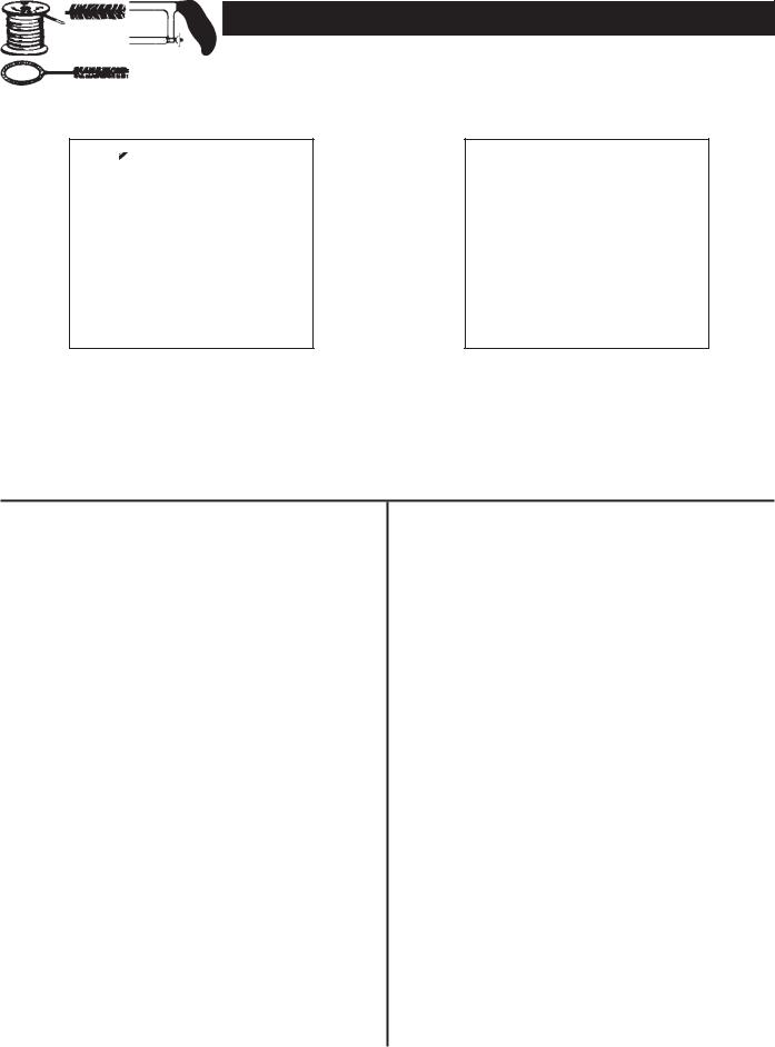
ROLL OF TEFLON TAPE (USE ON
WATER CONNECTIONS)
DRILL
SLOT-HEAD SCREWDRIVER
PHILLIPS SCREWDRIVER
PIPE DOPE (SQUEEZE TUBE)
USE FOR WATER CONNECTIONS
GARDEN HOSE |
6 FOOT TAPE |
PIPE WRENCH |
Additional Tools Needed When Sweat
Soldering
Tubing Cutters or Hacksaw Propane Torch
Soft Solder
Solder Flux
Emery Cloth
Wire Brushes
TUBING CUTTER
HACKSAW
ROLL OF |
ROLL OF |
|
EMERY CLOTH |
LEAD-FREE |
SOLDER |
|
SOFT SOLDER |
FLUX |
|
3/4” (19 mm) WIRE BRUSH |
PROPANE |
|
TORCH |
1/2” (13 mm) WIRE BRUSH |
6
INSTALLATION INSTRUCTIONS
Removing the Old Water Heater
FIGURE 1.
1. Turn “OFF” electrical supply to the water heater.
FIGURE 2.
2.Turn “OFF” the water supply to the water heater at the water shut-off valve or water meter.
FIGURE 3.
3.Attach a hose to the water heater drain valve and put the other end in a floor drain or outdoors. Open the water heater drain valve. Open a nearby hot water faucet which will relieve pressure in the water heater and speed draining.
FIGURE 4.
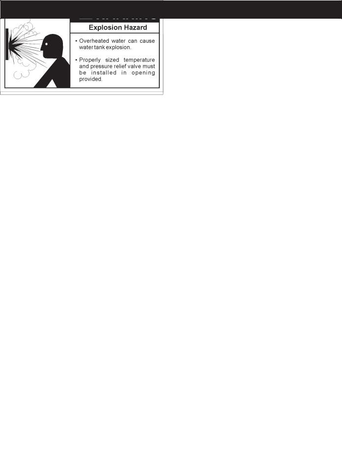
The water passing out of the drain valve may be extremely hot. To avoid being scalded, make sure all connections are tight and that the water flow is directed away from any person.
4.Check again to make sure the electrical supply is turned “OFF” to the water heater. Then unplug the water heater (cord set) or disconnect the electrical supply connection from the water heater junction box.
FIGURE 5.
5.a. If you have copper piping to the water heater, the two copper water pipes can be cut with a hacksaw approximately four inches away from where they connect to the water heater. This will avoid cutting off the pipes too short. Additional cuts can be made later if necessary. Disconnect the temperature-pressure relief valve drain line. When the water heater is drained, disconnect the hose from the drain valve. Close the drain valve. The water heater is now completely disconnected and ready to be removed.
FIGURE 6.
b.If you have galvanized pipe to the water heater, loosen the two galvanized pipes with a pipe wrench at the union in each line. Also disconnect the piping remaining to the water heater. These pieces should be saved since they may be needed when reconnecting the new water heater. Disconnect the temperature-pressure relief valve drain line. When the water heater is drained, disconnect the hose from the drain valve. Close the drain valve. The water heater is now completely disconnected and ready to be removed.
7
FIGURE 7.
Mineral buildup or sediment may have accumulated in the old water heater. This causes the water heater to be much heavier than normal and this residue, if spilled out, could cause staining.
Locating the New Water Heater
You should carefully choose an indoor location for the new water heater, because the placement is a very important consideration for the safety of the occupants in the building and for the most economical use of the appliance. This water heater is not intended for outdoor installation.
Whether replacing an old water heater or putting the water heater in a new location, the following critical points must be observed.
•The location selected should be indoors as close to and as centralized with the water piping system as possible. This water heater, as well as all water heaters, will eventually leak. Do not install without adequate drainage provisions so water flow will not cause damage.
Water heater life depends upon water quality, water pressure and the environment in which the water heater is installed. Water heaters are sometimes installed in locations where leakage may result in property damage, even with the use of a drain pan piped to a drain. However, unanticipated damage can be reduced or prevented by a leak detector or water shutoff device used in conjunction with a piped drain pan. These devices are available from some plumbing supply wholesalers and retailers, and detect and react to leakage in various ways:
•Sensors mounted in the drain pan that trigger an alarm or turn off the incoming water to the water heater when leakage is detected.
•Sensors mounted in the drain pan that turn off the water supply to the entire home when water is detected in the drain pan.
•Water supply shut-off devices that activate based on the water pressure differential between the cold water and hot water pipes connected to the water heater.
INSULATION BLANKETS
Insulation blankets are available to the general public for external use on electric water heaters but are not necessary with this product. The purpose of an insulation blanket is to reduce the standby heat loss encountered with storage tank heaters. Your water heater meets or exceeds the National Appliance Energy Conversation Act standards with respect to insulation and standby loss requirements, making an insulation blanket unnecessary.
Should you choose to apply an insulation blanket to this heater, you should follow these instructions below. Failure to follow these instructions can result in fire, serious personal injury, or death.
•Do not cover the temperature and pressure relief (T & P) valve with an insulation blanket.
•Do not cover the instruction manual. Keep it on the side of the water heater or nearby for future reference.
•Do obtain new warning and instruction labels for placement on the blanket directly over the existing labels.
Typical Installation
Check all connections for leaks. Consult the local utility company to examine installation for propriety and safety.
HOTTER WATER CAN SCALD: Water heaters are intended to produce hot water. Water heated to a temperature which will satisfy clothes washing, dish washing, and other sanitizing needs can scald and permanently injure you upon contact. Some people are more likely to be permanently injured by hot water than others. These include the elderly, children, the infirm, or physically/mentally handicapped. If anyone using hot water in your home fits into one of these groups or if there is a local code or state law requiring a certain temperature water at the hot water tap, then you must take special precautions. In addition to using the lowest possible temperature setting that satisfies your hot water needs, a means such as a mixing valve, shall be used at the hot water taps used by these people or at the water heater. Mixing valves are available at plumbing
8
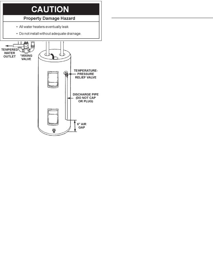
supply or hardware stores. Follow manufacturers instructions for installation of the valves. Before changing the factory setting on the thermostat, read the “Temperature Regulation” section in this manual.
INSTALLATION IN RESIDENTIAL GARAGES: The water heater must be located and/or protected so it is not subject to physical damage by a moving vehicle.
•The location selection must provide adequate clearances for servicing and proper operation of the water heater.
The Convertible Lower Element
The Upper Element, is a conventional 3800 watt element which only operates at its rated wattage on 240 volts. (See rating plate on the water heater).
The Lower Element of the water heater can be converted from operation at 3800 watts to 5500 watts on a 240 volt system.
Read and follow water heater warnings and instructions. If after reading these instructions in this manual, you do not understand any portion, call Maytag Customer Service at
1-800-788-8899 for an authorized sevicer.
FIGURE 8
WATER HEATERS EVENTUALLY LEAK: Installation of the water heater must be accomplished in such a manner that if the tank or any connections should leak, the flow of water will not cause damage to the structure. For this reason, it is not advisable to install the water heater in an attic or upper floor. When such locations cannot be avoided, a suitable drain pan should be installed under the water heater. Drain pans are available at your local hardware store. Such a drain pan must have a minimum length and width of at least 1 3/4 inches greater than the water heater dimensions and must be piped to an adequate drain.
Before making the conversion to 5500 watts, check the (1) power supply . . . must be 240 volts, (2) wiring . . . 10 gauge AWG @ Type TW, 60°C or equivalent, and (3) Circuit breakers or fusing . . .capable of 30 amp loading. Also, the installation must conform with this manual, local codes and electric utility rules. Failure to comply can result in DEATH, SERIOUS BODILY INJURY, OR PROPERTY DAMAGE.
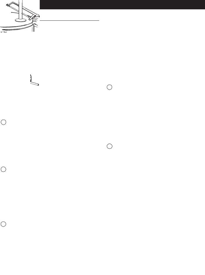
NOTE: Whether or not the element conversion is made the model rating plate must be marked. Using a hard point ink pen, check the appropriate block within the model rating plate, which is located adjacent to the lower access panel.
9
 Loading...