


Maytag HR630DJRT, HR6120SJRT, HR650DJLS, HR630DJLS, HR666DJRT User Manual
...Series Six
ELECTRIC
WATER HEATER USER’S GUIDE
GAMA certification applies to all residential electric water heaters with capacities of 20 to 120 Gallons. Input rating of 12 Kw or less at a voltage no greater than 250 V.
 WARNING
READ THE GENERAL SAFETY SECTION BEGINNING ON INSIDE COVER AND THEN THIS ENTIRE MANUAL BEFORE INSTALLING OR OPERATING THIS WATER HEATER.
Save this Manual for Future Reference.
Model Numbers
HR630SJRT HR630DJRT HR630SJLS HR630DJLS HR640SJRT HR640DJRT HR640SJRS HR640DJRS HR640SJLS HR640DJLS HR652SJRT HR652DJRT HR650SJRS HR650DJRS HR650SJLS HR650DJLS HR666SJRT HR666DJRT HR682SJRT HR682DJRT HR6120SJRT HR6120DJRT
FOR POTABLE WATER HEATING ONLY
NOT SUITABLE FOR SPACE HEATING
Caution:
Read and Follow All
Safety Rules and
Operating Instructions
Before First Use of
This Product.
Printed in the U.S.A. 0105 |
Part No. 66001869 |
|
184740-001 |
Safety Instructions
 WARNING
Improper installation, adjustment, alteration, service or maintenance can cause DEATH, SERIOUS BODILY INJURY, OR PROPERTY DAMAGE. Refer to this manual for assistance consult your local utility or call Maytag Customer Service at 1-800-788-8899 for an authorized servicer for further information.
 WARNING
HAZARD OF ELECTRICAL SHOCK! Before removing any access panels or servicing the water heater, make sure the electrical supply to the water heater is turned “OFF”. Failure to do this could result in DEATH, SERIOUS BODILY INJURY, OR PROPERTY DAMAGE.
 WARNING
HOTTER WATER CAN SCALD: Water heaters are intended to produce hot water. Water heated to a temperature which will satisfy clothes washing, dish washing, and other sanitizing needs can scald and permanently injure you upon contact. Some people are more likely to be permanently injured by hot water than others. These include the elderly, children, the infirm, or physically/mentally handicapped. If anyone using hot water in your home fits into one of these groups or if there is a local code or state law requiring a certain temperature water at the hot water tap, then you must take special precautions. In addition to using the lowest possible temperature setting that satisfies your hot water needs, a means such as a mixing valve, should be used at the hot water taps used by these people or at the water heater. Mixing valves are available at plumbing supply or hardware stores. Follow manufacturers instructions for installation of the valves. Before changing the factory setting on the thermostat, read the “Temperature Regulation” section in this manual.
 WARNING
INSULATING JACKETS: When installing an external water heater insulation jacket on an electric water heater:
•DO NOT cover the temperature-pressure relief valve.
•DO NOT put insulation over the access covers or any access areas.
•DO NOT remove operating instructions, and safety related warning labels and materials affixed to the water heater.
•DO obtain new warning and instruction labels from Maytag for placement on the jacket directly over the existing labels.
 WARNING
Do not use this appliance if any part of it has been under water. An electrical short or malfunction could occur. The water heater should be replaced.
 WARNING
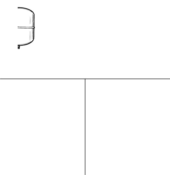
At the time of manufacture this water heater was provided with a combination temperature-pressures relief valve certified by a nationally recognized testing laboratory that maintains periodic inspection of production of listed equipment or materials, as meeting the requirements for Relief Valves and Automatic Gas Shutoff Devices for Hot Water Supply Systems, and the current edition of ANSI Z21.22 • CSA 4.4 and the code requirements of ASME. If replaced, the valve must meet the requirements of local codes, but not less than a combination temperature and pressure relief valve certified as meeting the requirements for Relief Valves and Automatic Gas Shutoff Devices for Hot Water Supply Systems, ANSI Z21.22 • CSA 4.4 by a nationally recognized testing laboratory that maintains periodic inspection of production of listed equipment or materials.
The valve must be marked with a maximum set pressure not to exceed the marked hydrostatic working pressure of the water heater (150 lbs./sq. in.) and a discharge capacity not less than the water heater input rate as shown on the model rating plate. (Electric heaters - watts divided by 1000 x 3412 equal BTU/Hr. rate.)
Your local jurisdictional authority, while mandating the use of a temperature-pressure relief valve complying with ANSI Z21.22 • CSA 4.4 and ASME, may require a valve model different from the one furnished with the water heater.
Compliance with such local requirements must be satisfied by the installer or end user of the water heater with a locally prescribed temperature-pressure relief valve installed in the designated opening in the water heater in place of the factory furnished valve. For safe operation of the water heater, the relief valve must not be removed from it’s designated opening or plugged.
The temperature-pressure relief valve must be installed directly into the fitting of the water heater designated for the relief valve. Position the valve downward and provide tubing so that any discharge will exit only within 6 inches above, or at any distance below the structural floor. Be certain that no contact is made with any live electrical part. The discharge opening must not be blocked or reduced in size under any circumstances. Excessive length, over 30 feet, or use of more than four elbows can cause restriction and reduce the discharge capacity of the valve.
No valve or other obstruction is to be placed between the relief valve and the tank. Do not connect tubing directly to discharge drain unless a 6” air gap is provided. To prevent bodily injury, hazard to life, or property damage, the relief valve must be allowed to discharge water in quantities should circumstances demand. If the discharge pipe is not connected to a drain or other suitable means, the water flow may cause property damage.
The Discharge Pipe:
•Must not be smaller in size than the outlet pipe size of the valve, or have any reducing couplings or other restrictions.
•Must not be plugged or blocked.
•Must be of material listed for hot water distribution.
•Must be installed so as to allow complete drainage of both the temperature-pressure relief valve, and the discharge pipe.
•Must terminate at an adequate drain.
•Must not have any valve between the relief valve and tank.
2

Safety Instructions (cont’d)
 WARNING
WATER HEATERS EQUIPPED FOR ONE VOLTAGE ONLY: This water heater is equipped for one type voltage only. Check the rating plate near the bottom access panel for the correct voltage. DO NOT use this water heater with any voltage other than the one shown on the model rating plate. Failure to use the correct voltage can cause problems which can result in DEATH, SERIOUS BODILY INJURY, OR PROPERTY DAMAGE. If you have any questions or doubts consult your electric company.
 WARNING
HYDROGEN GAS: Hydrogen gas can be produced in a hot water system that has not been used for a long period of time (generally two weeks or more). Hydrogen gas is extremely flammable and explosive. To prevent the possibility of injury under these conditions, we recommend the hot water faucet be opened for several minutes at the kitchen sink before any electrical appliances which are connected to the hot water system are used (such as a dishwasher or washing machine). If hydrogen gas is present, there will probably be an unusual sound similar to air escaping through the pipe as the hot water faucet is opened. There must be no smoking or open flame near the faucet at the time it is open.
 CAUTION
WATER HEATERS EVENTUALLY LEAK: Installation of the water heater must be accomplished in such a manner that if the tank or any connections should leak, the flow of water will not cause damage to the structure. For this reason, it is not advisable to install the water heater in an attic or upper floor. When such locations cannot be avoided, a suitable drain pan should be installed under the water heater. Drain pans are available at your local hardware store. Such a drain pan must have a minimum diameter of at least 13/4 inches greater than the water heater diameter and must be piped to an adequate drain.
 CAUTION
Never use this water heater unless it is completely full of water. To prevent damage to the tank and heating element, the tank must be filled with water. Water must flow from the hot water faucet before turning “ON” power.
3
Table of Contents |
|
Safety Instructions..................................................................................................................... |
2,3 |
Table of Contents........................................................................................................................... |
4 |
Customer Information.............................................................................................................. |
5 |
Product Specifications......................................................................................................... |
5-7 |
Accessories and Tools Needed................................................................................ |
8 |
Accessories .......................................................................................................................................................... |
8 |
Tools ..................................................................................................................................................................... |
8 |
Instructions for Installation.......................................................................................... |
9-15 |
Removing the Old Water Heater .......................................................................................................................... |
9 |
Locating the New Water Heater ......................................................................................................................... |
10 |
Typical Installation .............................................................................................................................................. |
10 |
Water Piping ....................................................................................................................................................... |
11 |
T&P Valve and Pipe Insulation ........................................................................................................................ |
11 |
Temperature-Pressure Relief Valve.................................................................................................................... |
12 |
Filling the Water Heater...................................................................................................................................... |
13 |
Wiring Diagrams................................................................................................................................................. |
13 |
Wiring ................................................................................................................................................................. |
14 |
Installation Checklist........................................................................................................................................... |
15 |
Service and Maintenance .......................................................................................... |
16-21 |
Temperature Regulation ..................................................................................................................................... |
16 |
Thermostats........................................................................................................................................................ |
16 |
Temperature Settings ......................................................................................................................................... |
16 |
Thermostat Adjustments..................................................................................................................................... |
17 |
Anode Rod Inspection ........................................................................................................................................ |
17 |
Temperature-Pressure Relief Valve Operation ................................................................................................... |
17 |
Draining .............................................................................................................................................................. |
18 |
Thermostat Removal/Replacement ............................................................................................................... |
18,19 |
Element Cleaning and Replacement............................................................................................................. |
19-21 |
Drain Valve Washer Replacement...................................................................................................................... |
21 |
Service................................................................................................................................................................ |
21 |
Troubleshooting ........................................................................................................................ |
22-24 |
Start Up Conditions............................................................................................................................................. |
22 |
Thermal Expansion ........................................................................................................................................ |
22 |
Strange Sounds.............................................................................................................................................. |
22 |
Operational Conditions.................................................................................................................................. |
22,23 |
Smelly Water.................................................................................................................................................. |
22 |
Air in Hot Water Faucets ................................................................................................................................ |
22 |
Rumbling Noise.............................................................................................................................................. |
22 |
High Temperature Shut Off System .......................................................................................................... |
22,23 |
Not Enough Hot Water ................................................................................................................................... |
23 |
Water is Too Hot............................................................................................................................................. |
23 |
Leakage Checkpoints..................................................................................................................................... |
24 |
Repair Parts List....................................................................................................................... |
26-34 |
Warranty.................................................................................................................................................... |
36 |
4
Customer In formation
Thank You for purchasing a Maytag water heater. Properly installed and maintained, it should give you years of trouble free service. It is strongly suggested that this new water heater be professionally installed, call Maytag Customer Service at1-800-788-8899 for recommended installers.
Abbreviations Found In This Instruction
Manual
U.L. - Underwriters Laboratories Inc.
NEC - National Electrical Code
ANSI - American National Standards Institute
•Read the “Safety Instructions” section, pages 2 and 3 of this manual first and then the entire manual carefully. If you don’t follow the safety rules, the water heater will not operate properly. It could cause DEATH, SERIOUS BODILY INJURY AND/OR PROPERTY DAMAGE.
This manual contains instructions for the installation, operation, and maintenance of this electric water heater. It also contains warnings throughout the manual that you must read and be aware of. All warnings and all instructions are essential to the proper operation of the water heater and your safety. Since we cannot put everything on the first few pages, READ THIS ENTIRE MANUAL BEFORE ATTEMPTING TO INSTALL OR OPERATE THE WATER HEATER.
•The installation must conform with the instructions in this manual; electric company rules; and Local Codes, or in
the absence of Local Codes, with the current edition of the NEC - National Electrical Code NFPA 70. This publication is available from your local government or public library or electric company or by writing Underwriters Laboratories Inc., 333 Pfingsten Road, Northbrook, IL 60062.
•If after reading this manual you have any questions or do not understand any portion of the instructions, call Maytag Customer Service at 1-800-788-8899 for an authorized servicer.
•Carefully plan the place where you are going to put the water heater. Correct electrical wiring and connections are very important in preventing death from possible electrical shock and fires.
Examine the location to ensure the water heater complies with the “Locating the New Water Heater” section.
•For California installation this water heater must be braced, anchored, or strapped to avoid falling or moving during an earthquake. See instructions for correct installation procedures. Instructions may be obtained from the California office of the State Architect, 400 P Street, Sacramento, CA 95814.
•Massachusetts Code requires this water heater to be installed in accordance with Massachusetts 248-CMR 2.00: State Plumbing Code and 248-CMR 5.00.
Product Specifications
Model |
|
HR630SJRT |
HR630DJRT |
HR630SJLS |
HR630DJLS |
HR640SJRT |
|
|
|
|
|
|
|
Tank Capacity |
|
|
|
|
|
|
In Gal. |
|
30 |
30 |
30 |
30 |
40 |
*Element |
Upper |
— |
4500 |
— |
4500 |
— |
Wattage |
|
|
|
|
|
|
|
|
|
|
|
|
|
at 240 Volt |
Lower |
4500 |
4500 |
4500 |
4500 |
4500 |
Recovery Rate Upper |
— |
20 |
— |
20 |
— |
|
In Gals Per Hr. |
|
|
|
|
|
|
|
|
|
|
|
|
|
@ 90°F Rise |
Lower |
20 |
20 |
20 |
20 |
20 |
|
|
|
|
|
|
|
Diameter |
|
18” |
18" |
22" |
22" |
18" |
Height |
|
46 1/2” |
46 1/2” |
30” |
30” |
59 1/2” |
Maximum Fuse or |
|
|
|
|
|
|
Circuit Breaker Size |
30 |
30 |
30 |
30 |
30 |
|
Minimum |
|
|
|
|
|
|
Wire Size (Gauge) |
10 |
10 |
10 |
10 |
10 |
|
*Standard element wattages are shown. Other element wattages (up to the maximum shown) are available when specified. *Wiring size based on standard 60°C copper wire. If distance from fuse box to water heater is more than 90 feet, refer to your local
electrical code.
5
Product Specifications
Model |
|
HR640DJRT |
HR640SJRS |
HR640DJRS |
HR640SJLS |
HR640DJLS |
|
|
|
|
|
|
|
|
|
Tank Capacity |
40 |
40 |
40 |
40 |
40 |
||
In Gal. |
|
||||||
*Element |
Upper |
4500 |
— |
4500 |
— |
4500 |
|
Wattage |
|
|
|
|
|
|
|
Lower |
4500 |
4500 |
4500 |
4500 |
4500 |
||
at 240 Volt |
|||||||
Recovery Rate Upper |
20 |
— |
20 |
— |
20 |
||
In Gals. Per Hr. |
|
|
|
|
|
|
|
|
|
|
|
|
|
||
@ 90°F Rise |
Lower |
20 |
20 |
20 |
20 |
20 |
|
Diameter |
|
18” |
20 1/2” |
20 1/2” |
25” |
25” |
|
Height |
|
59 1/2” |
44” |
44” |
32 1/4” |
32 1/4” |
|
Maximum Fuse or |
30 |
30 |
30 |
30 |
30 |
||
Circuit Breaker Size |
|||||||
Minimum |
|
10 |
10 |
10 |
10 |
10 |
|
Wire Size (Gauge) |
|||||||
|
|
|
|
|
|
|
|
Model |
|
HR652SJRT |
HR652DJRT |
HR650SJRS |
HR650DJRS |
HR650SJLS |
|
|
|
|
|
|
|
||
Tank Capacity |
50 |
50 |
50 |
50 |
50 |
||
In Gal. |
|
||||||
*Element |
Upper |
— |
4500 |
— |
4500 |
— |
|
Wattage |
|
|
|
|
|
|
|
Lower |
4500 |
4500 |
4500 |
4500 |
4500 |
||
at 240 Volt |
|||||||
Recovery Rate Upper |
— |
20 |
— |
20 |
— |
||
In Gals. Per Hr. |
|
|
|
|
|
|
|
|
|
|
|
|
|
||
@ 90°F Rise |
Lower |
20 |
20 |
20 |
20 |
20 |
|
Diameter |
|
20 1/2” |
20 1/2” |
22” |
22” |
26 1/2” |
|
Height |
|
54” |
54” |
48” |
48” |
34” |
|
Maximum Fuse or |
30 |
30 |
30 |
30 |
30 |
||
Circuit Breaker Size |
|||||||
Minimum |
|
10 |
10 |
10 |
10 |
10 |
|
Wire Size (Gauge) |
|||||||
|
|
|
|
|
|
|
|
Model |
|
HR650DJLS |
HR666SJRT |
HR666DJRT |
HR682SJRT |
HR682DJRT |
|
|
|
|
|
|
|
||
Tank Capacity |
50 |
66 |
66 |
80 |
80 |
||
In Gal. |
|
||||||
*Element |
Upper |
4500 |
— |
4500 |
— |
4500 |
|
Wattage |
|
|
|
|
|
|
|
Lower |
4500 |
4500 |
4500 |
4500 |
4500 |
||
at 240 Volt |
|||||||
Recovery Rate Upper |
20 |
— |
20 |
— |
20 |
||
In Gals. Per Hr. |
|
|
|
|
|
|
|
|
|
|
|
|
|
||
@ 90°F Rise |
Lower |
20 |
20 |
20 |
20 |
20 |
|
Diameter |
|
26 1/2” |
22” |
22” |
24” |
24” |
|
Height |
|
34” |
60 1/4” |
60 1/4” |
60 1/2” |
60 1/2” |
|
Maximum Fuse or |
30 |
30 |
30 |
30 |
30 |
||
Circuit Breaker Size |
|||||||
Minimum |
|
10 |
10 |
10 |
10 |
10 |
|
Wire Size (Gauge) |
|||||||
*Standard element wattages are shown. Other element wattages (up to the maximum shown) are available when specified. *Wiring size based on standard 60°C copper wire. If distance from fuse box to water heater is more than 90 feet, refer to your local
electrical code.
6
Product Specifications
Model |
|
|
HR6120SJRT |
HR6120DJRT |
|
|
|
|
|
||
Tank Capacity |
119 |
119 |
|||
In Gal. |
|
|
|||
*Element |
Upper |
— |
4500 |
||
Wattage |
|
|
|
|
|
Lower |
4500 |
4500 |
|||
at 240 Volt |
|||||
Recovery Rate Upper |
— |
20 |
|||
In Gals. Per Hr. |
|
|
|
|
|
|
|
|
|
||
@ 90°F Rise |
|
Lower |
20 |
20 |
|
Diameter |
|
|
28” |
28” |
|
Height |
|
|
64 1/4” |
64 1/4” |
|
Maximum Fuse or |
30 |
30 |
|||
Circuit Breaker Size |
|||||
Minimum |
|
|
10 |
10 |
|
Wire Size (Gauge) |
|||||
*Standard element wattages are shown. Other element wattages (up to the maximum shown) are available when specified. *Wiring size based on standard 60°C copper wire. If distance from fuse box to water heater is more than 90 feet, refer to your local
electrical code.
7
Accessories and Tools Needed
Accessories
To simplify the installation Maytag has available the installation parts shown below. You may or may not need all of these accessories depending on your type of installation. Call Maytag Customer Service at 1-800-788-8899 for an authorized installer.
EXPANSION TANKS FOR THERMAL EXPANSION CONDITIONS AVAILABLE IN 2 GALLON (PART NUMBER 66001013) AND 5 GALLON (PART NUMBER 66001014) CAPACITY
DRAIN PANS AVAILABLE IN 22” DIAMETER (PART NUMBER 66001011) FOR WATER HEATERS HAVING A DIAMETER 20” OR LESS, 24” DIAMETER (PART NUMBER 66001105) FOR WATER HEATERS HAVING A DIAMETER 22” OR LESS AND AVAILABLE IN 28” DIAMETER (PART NUMBER 66001012) FOR WATER HEATERS HAVING A DIAMETER 26.25” OR LESS
Tools
You may or may not need all of these tools, depending on your type of installation. These tools can be purchased at your local Maytag store.
•Pipe Wrenches (2) 14”
•Screwdriver
•6 Foot Tape or Folding Rule
•Garden Hose
•Drill
•Pipe dope or Teflon Tape
6 FOOT TAPE
GARDEN HOSE
SLOT-HEAD SCREW DRIVER
PIPE
WRENCH
PHILLIPS SCREWDRIVER
PIPE DOPE
(SQUEEZE TUBE)
ROLL OF TEFLON TAPE |
DRILL |
(Use only on water connections) |
|
ADDITIONAL TOOLS NEEDED
WHEN SWEAT SOLDERING
•Tubing Cutters or Hacksaw
•Propane Torch
•Soft Solder
•Solder Flux
•Emery Cloth
•Wire Brushes
|
HACKSAW |
|
|
|
|
||
|
|
|
|
|
|
||
|
|
|
|
|
|
|
|
|
|
3/4” WIRE BRUSH |
|
|
|||
|
|
|
|
|
|
|
|
|
|
|
|
|
|
||
|
|
|
1/2” WIRE BRUSH |
|
|||
|
|
|
|
|
|
|
PROPANE TORCH |
ROLL OF LEAD FREE |
|
|
|
||||
|
|
|
|
||||
|
SOFT SOLDER |
|
|
|
|
||
ROLL OF EMERY |
SOLDER |
TUBING |
|||||
|
CLOTH |
FLUX |
CUTTER |
||||
8
Installation Instructions
Removing the Old Water Heater
1 
2Turn “OFF” the water supply to the water heater at the water shutoff valve or water meter.
5a. If you have copper piping to the water heater, the two copper water pipes can be cut with a hacksaw approximately four inches away from where they connect to the water heater. This will avoid cutting off the pipes too short. Additional cuts can be made later if necessary. Disconnect the temperature-pressure relief valve drain line. When the water heater is drained, disconnect the hose from the drain valve. Close the drain valve. The water heater is now completely disconnected and ready to be removed.
|
|
|
5 |
|
1 |
||||
|
||||
|
|
|
|
4
3Attach a hose to the water heater drain valve and put the other end in a floor drain or outdoors. Open the water heater drain valve. Open a nearby hot water faucet which will relieve pressure in the water heater and speed draining.
 WARNING
The water passing out of the drain valve may be extremely hot. To avoid being
scalded, make sure all connections are 3 tight and that the water flow is directed
away from any person.
4Check again to make sure the electrical supply is turned “OFF” to the water heater. Then disconnect the electrical supply connection from the water heater junction box.
5b. If you have galvanized pipe to the water heater, loosen the two galvanized pipes with a pipe wrench at the union in each line. Also disconnect the piping remaining to the water heater. These pieces should be saved since they may be needed when reconnecting the new water heater. Disconnect the temperaturepressure relief valve discharge pipe. When the water heater is drained, disconnect the hose from the drain valve. Close the drain valve. The water heater is now completely disconnected and ready to be removed
 CAUTION
Mineral buildup or sediment may have accumulated in the old water heater. This causes the water heater to be much heavier than normal and this residue, if spilled out, could cause staining.
9

Instructions for Installation (cont’d)
Locating The New Water
Heater
You should carefully choose an indoor location for the new water heater, because the placement is a very important consideration for the safety of the occupants in the building and for the most economical use of the appliance. This water heater is not intended for outdoor installation.
Whether replacing an old water heater or putting the water heater in a new location, the following critical points must be observed.
1.The location selected should be indoors as close to and as centralized with the water piping system as possible. This water heater, as well as all water heaters, will eventually leak. Do not install without adequate drainage provisions where water flow will cause damage.
 CAUTION
WATER HEATERS EVENTUALLY LEAK: Installation of the water heater must be accomplished in such a manner that if the tank or any connections should leak, the flow of water will not cause damage to the structure. For this reason, it is not advisable to install the water heater in an attic or upper floor. When such locations cannot be avoided, a suitable drain pan should be installed under the water heater. Drain pans are available at your local hardware store. Such a drain pan must have a minimum diameter of at least 1 3/4 inches greater than the water heater diameter and must be piped to an adequate drain.
 CAUTION
INSTALLATION IN RESIDENTIAL GARAGES: The water heater must be located and/or protected so it is not subject to physical damage by a moving vehicle.
2. The location selection must provide adequate clearances for servicing and proper operation of the water heater.
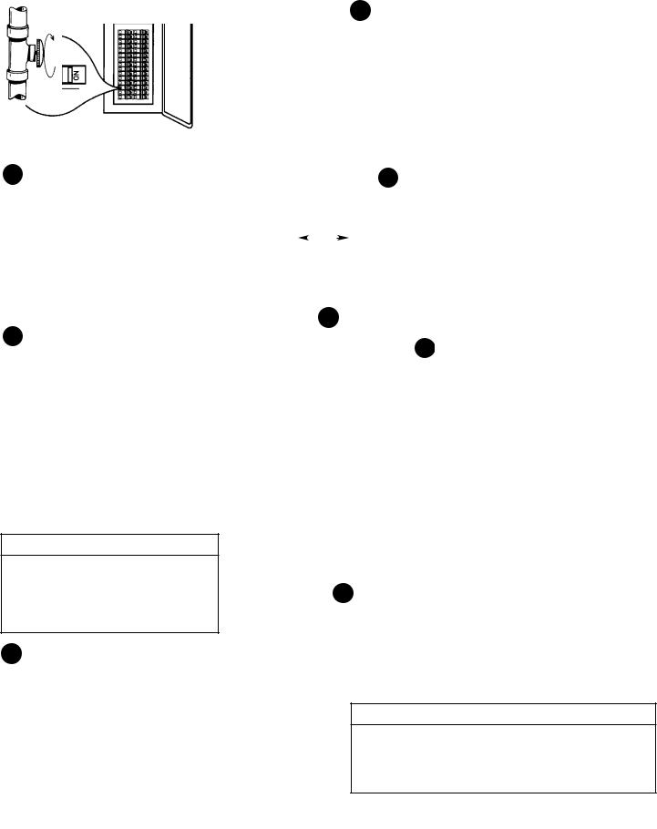
Typical Installation
CHECK ALL CONNECTIONS FOR LEAKS. CONSULT THE LOCAL UTILITY COMPANY TO EXAMINE INSTALLATION FOR PROPRIETY AND SAFETY.
* WARNING
HOTTER WATER CAN SCALD: Water heaters are intended to produce hot water. Water heated to a temperature which will satisfy clothes washing, dish washing, and other sanitizing needs can scald and permanently injure you upon contact. Some people are more likely to be permanently injured by hot water than others. These include the elderly, children, the infirm, or physically/mentally handicapped. If anyone using hot water in your home fits into one of these groups or if there is a local code or state law requiring a certain temperature water at the hot water tap, then you must take special precautions. In addition to using the lowest possible temperature setting that satisfies your hot water needs, a means such as a mixing valve, should be used at the hot water taps used by these people or at the water heater. Mixing valves are available at plumbing supply or hardware stores. Follow manufacturers instructions for installation of the valves. Before changing the factory setting on the thermostat, read the “Temperature Regulation” section in this manual.
VACUUM RELIEF REQUIRED BY SOME CODES (REFER TO LOCAL CODES) 
|
|
|
|
HOT WATER |
COLD WATER INLET |
||||||
|
|
|
|
OUTLET |
|||||||
|
|
|
|
|
ELBOW |
|
|
|
|
|
|
UNION |
|
|
|
UNION |
|
|
|||||
|
|
|
|
|
|
|
|
|
|
|
|
|
|
|
|
|
|
|
|
|
|
||
TEMPERED |
|
|
|
3/4” THREADED |
|||||||
|
|
|
CONNECTORS |
||||||||
WATER |
|
|
|
|
|
|
|||||
|
|
|
|
|
|
||||||
OUTLET |
*MIXING VALVE |
|
|
|
|
|
|
|
|||
|
|
|
|
|
|
|
|
|
|
|
|
|
|
|
ELECTRICAL |
|
|
|
|
|
|
||
|
|
JUNCTION BOX |
|
|
|
TEMPERATURE- |
|||||
|
|
|
|||||||||
|
|
|
|
|
|
|
|
|
PRESSURE |
||
|
|
|
|
|
ACCESS COVER |
|
|
|
RELIEF VALVE |
||
|
|
|
|
|
|
|
|
|
|
|
|
|
|
|
|
|
|
|
|
|
|
|
|
|
|
|
|
|
|
|
|
|
DISCHARGE |
|
|
|
|
|
|
|
|
|
|
|
|
||
|
|
|
|
|
|
|
|
|
PIPE |
|
|
|
|
|
|
|
|
|
|
|
(Do not cap |
|
|
|
|
|
|
|
|
|
|
|
or plug) |
|
|
|
|
|
|
|
ACCESS COVER |
|
|
|
DRAIN VALVE |
||
|
|
|
|
|
|
|
|
|
|||
 6” AIR GAP
TO SUITABLE DRAIN
10
Instructions for Installation (cont’d)
Water Piping
* WARNING
HOTTER WATER CAN SCALD: Water heaters are intended to produce hot water. Water heated to a temperature which will satisfy clothes washing, dish washing, and other sanitizing needs can scald and permanently injure you upon contact. Some people are more likely to be permanently injured by hot water than others. These include the elderly, children, the infirm, or physically/mentally handicapped. If anyone using hot water in your home fits into one of these groups or if there is a local code or state law requiring a certain temperature water at the hot water tap, then you must take special precautions. In addition to using the lowest possible temperature setting that satisfies your hot water needs, a means such as a mixing valve, should be used at the hot water taps used by these people or at the water heater. Mixing valves are available at plumbing supply or hardware stores. Follow manufacturers instructions for installation of the valves. Before changing the factory setting on the thermostat, read the “Temperature Regulation” section in this manual.
*See illustration on page 10 for mixing valve usage.
The illustration shows the attachment of the water piping to the water heater. The water heater is equipped with 3/4 inch water connections.
If a water heater is installed in a closed water supply system; such as one having a back-flow preventer, check valve, water meter with a check valve, etc. in the cold water supply; means shall be provided to control thermal expansion. Contact the local utility or call Maytag Customer Service at 1-800-788-8899 for an authorized servicer on how to control this situation.
NOTE: Your water heater is super insulated to minimize heat loss from the tank. Further reduction in heat loss can be accomplished by insulating the hot water lines from the water heater.
HOT OUTLET |
SHUT-OFF |
COLD INLET |
||
TO HOUSE |
VALVE |
WATER LINE |
||
|
|
|
|
|
THREADED TO |
|
|
|
|
THREADED TO |
|
SWEAT COUPLING |
|
|
|
SWEAT COUPLING |
||
3/4” THREADED |
|
|
|
|
3/4” THREADED |
|
|
|
|
|
|||
NIPPLE |
|
HOT |
COLD |
|
|
NIPPLE |
|
|
|
|
|
|
|
|
|
|
|
|
|
TEMPERATURE- |
|
|
|
|
|
|
PRESSURE |
|
|
|
|
|
|
RELIEF VALVE |
|
|
|
|
|
|
|
DISCHARGE PIPE (Do not cap or plug)
6” AIR GAP
FLOOR DRAIN
NOTE: If using copper tubing, solder tubing to an adapter before attaching the adaptor to the cold water inlet connection. Do not solder the cold water supply line directly to the cold water inlet. It will harm the dip tube and damage the tank.
NOTE: To protect against untimely corrosion of hot and cold water fittings, it is strongly recommended that di-electric unions or couplings be installed on this water heater when connected to copper pipe.
1.Look at the top cover of the water heater. The water outlet is marked hot. Connect the hot water pipe to the hot water outlet of the water heater.
2.Look at the top cover of the water heater. The cold water inlet is marked cold. Connect the cold water pipe to the cold water inlet of the water heater.
T&P Valve and Pipe Insulation
Remove insulation for T&P Valve and pipe connections from carton.
Fit pipe insulation over the incoming cold water line and the hot water line. Make sure that the insulation is against the top cover of the heater.
Fit T&P Valve insulation over valve. Make sure that the insulation does not interfere with the lever of the T&P valve.
Secure all insulation using tape.
11
 Loading...