


Service
This manual is to be used by qualified appliance technicians only. Maytag does not assume any responsibility for property damage or personal injury for improper service procedures done by an unqualified person.
This manual replaces RS2520001 Revision 0.
Electric
Wall Ovens
This Base Manual covers general information
Refer to individual Technical Sheet for information on specific models
This manual includes, but is not limited to the following:
AOES3030*
AOCS3040*
16021875 Revision 0 November 2003
Table of Contents |
|
Important Information ................................................ |
4 |
Important Safety Information |
|
All Appliances ..................................................... |
5 |
Ovens ................................................................. |
5 |
Self-Cleaning ...................................................... |
5 |
In Case of Fire .................................................... |
5 |
General Information |
|
Oven Operation ................................................... |
6 |
Cooking Guide .................................................... |
6 |
Convection Broiling Rack ..................................... |
7 |
Oven Rack Placement ......................................... |
7 |
Spacesaver™ Convection Rack ............................ |
7 |
Convection Pan Placement .................................. |
7 |
Pan Placement ................................................... |
7 |
Slow-Cook™ Roasting Rack ................................ |
7 |
Removing Oven Door ........................................... |
8 |
Replacing Oven Door ........................................... |
8 |
Replacing Oven Light ........................................... |
8 |
Titling Control Panel ............................................ |
8 |
Care and Cleaning |
|
Cleaning Oven Parts ............................................ |
9 |
Component Testing Information ............................... |
10 |
Testing Procedures |
|
Oven Door Switch.............................................. |
14 |
Oven High Limit/Fan Switch ............................... |
14 |
Oven Temperature Sensor .................................. |
14 |
Blower Motor .................................................... |
14 |
Auto Latch Motor .............................................. |
15 |
Convection Fan Motor ........................................ |
15 |
Convection Element Testing ............................... |
15 |
Broil Element Testing ........................................ |
15 |
Bake Element Testing ....................................... |
15 |
Disassembly Procedures |
|
Removing and Replacing Oven ........................... |
16 |
Control Panel .................................................... |
16 |
ERC/P.C. Board ................................................ |
16 |
Transformer/Relay Board .................................... |
16 |
Oven High Limit/Fan Control Switch .................... |
16 |
Oven Sensor ..................................................... |
17 |
Bake Element ................................................... |
17 |
Broil Element/Broil Element Reflector ................. |
17 |
Convection Heating Element .............................. |
17 |
Convection Fan Blade ........................................ |
17 |
Convection Fan Motor ........................................ |
17 |
Automatic Oven Door Latch Assembly ................ |
17 |
Door Plunger Light Switch.................................. |
17 |
Oven Light Bulb/Oven Light Socket ..................... |
18 |
Oven Tank Removal ........................................... |
18 |
Oven Door Removal ........................................... |
18 |
Frameless Door Disassembly ............................ |
18 |
Oven Door Hinge ............................................... |
19 |
Blower Motor .................................................... |
19 |
Vent Assembly/Smoke Eliminator ...................... |
19 |
Outer Trim Assembly ......................................... |
19 |
Appendix A |
|
Installation Instructions |
|
Packing Material ......................................... |
A-2 |
Oven Dimensions ........................................ |
A-2 |
Oven Location ............................................. |
A-2 |
Line Voltage Requirements .......................... |
A-2 |
Connecting Wiring ....................................... |
A-3 |
Wall Oven and Cooktop Combination |
|
Installation Specifications ............................ |
A-4 |
AKED3060 or AKES3060 Downdraft Cooktop |
|
above AOES3030 or AOCS3040 Wall Oven ... |
A-4 |
AKED3060 or AKES3060 Downdraft Cooktop |
|
above AOES3030 or AOCS3040 Wall Oven |
|
in an Island Application ................................ |
A-5 |
AK2H36, AK2T36, 36" Electric Cooktop |
|
Installed above AOES3030 or AOCS3040 |
|
Wall Oven .................................................. |
A-5 |
30" Electric Cooktop AK2H30, AK2T30, |
|
AKR3000, AKT3000, CAK2H30, CAK2T30 |
|
Installed above AOES3030 or AOCS3040 |
|
Wall Oven .................................................. |
A-6 |
AOES3030 or AOCS3040 Wall Oven |
|
Stacked Installation ..................................... |
A-6 |
AOES3030 or AOCS3040 Wall Oven |
|
Installed Side-by-Side .................................. |
A-7 |
Tilting Control Panel .................................... |
A-7 |
2 |
16021875 Rev. 0 |
©2003 Maytag Appliances Company |
Table of Contents
Appendix B |
|
Programming Instructions—ERC for |
|
AOES3030 |
|
Electronic Oven Control Options ................... |
B-2 |
Special Oven Control Functions .................... |
B-2 |
Quick Reference Instructions ....................... |
B-3 |
Bake .......................................................... |
B-4 |
Timed Bake ................................................ |
B-4 |
Delayed Bake ............................................. |
B-4 |
Broiling ....................................................... |
B-4 |
Self-Cleaning .............................................. |
B-5 |
Interrupt Self-Cleaning Cycle ........................ |
B-5 |
Delayed Self-Cleaning .................................. |
B-5 |
Interrupt Self-Cleaning Cycle ........................ |
B-5 |
Adjusting Oven Temperature ........................ |
B-6 |
Service Tones and Codes ............................. |
B-6 |
Testing Procedures |
|
Service Information ...................................... |
B-7 |
Quick Test Procedure .................................. |
B-7 |
ERC Warnings and Failure Codes ................ |
B-8 |
Temperature Calibration Offset ..................... |
B-8 |
Function Switch Connection |
|
Check Procedure ........................................ |
B-8 |
Transformer/Relay Module ............................ |
B-8 |
Double Line Break—K6................................ |
B-8 |
Bake Relay—K4 ......................................... |
B-8 |
Broil Relay—K5 .......................................... |
B-8 |
Oven Light Relay—K10 ................................ |
B-9 |
Door Lock Relay—K3 .................................. |
B-9 |
Display (Filament) Voltage ........................... |
B-9 |
Appendix C |
|
Programming Instructions—ERC for |
|
AOCS3040 |
|
Electronic Oven Control Options ................... |
C-2 |
Special Oven Control Functions .................... |
C-2 |
Quick Reference Instructions ....................... |
C-3 |
Bake and Convection Bake .......................... |
C-4 |
Timed Bake or Convection Bake ................... |
C-4 |
Delayed Bake or Convection Bake ................ |
C-4 |
Convection .................................................. |
C-4 |
Timed Convection ........................................ |
C-4 |
Delayed Convection ..................................... |
C-5 |
Broil and Convection Broil ............................ |
C-5 |
Convection Dehydration ............................... |
C-5 |
Dehydration Tips ......................................... |
C-5 |
Self-Cleaning .............................................. |
C-6 |
Interrupt Self-Cleaning Cycle ........................ |
C-6 |
Delayed Self-Cleaning .................................. |
C-6 |
Canceling Self-Cleaning Cycle ...................... |
C-6 |
Adjusting Oven Temperature ........................ |
C-6 |
Testing Procedures |
|
Service Information ...................................... |
C-7 |
Quick Test Procedure .................................. |
C-7 |
ERC Warnings and Failure Codes ................ |
C-8 |
Temperature Calibration Offset ..................... |
C-8 |
Function Switch Connection |
|
Check Procedures ....................................... |
C-8 |
Transformer/Relay Module ............................ |
C-8 |
Double Line Break—K6................................ |
C-8 |
Bake Relay—K4 ......................................... |
C-8 |
Broil Relay—K5 .......................................... |
C-8 |
Convection Element Relay—K2 .................... |
C-9 |
Convection Fan Relay—K1........................... |
C-9 |
Oven Light Relay—K10 ................................ |
C-9 |
Door Lock Relay—K3 .................................. |
C-9 |
©2003 Maytag Appliances Company |
16021875 Rev. 0 |
3 |
Important Information
Pride and workmanship go into every product to provide our customers with quality products. It is possible,
however, that during its lifetime a product may require service. Products should be serviced only by a qualified
Important Information
service technician who is familiar with the safety procedures required in the repair and who is equipped with the proper tools, parts, testing instruments and the appropriate service manual. REVIEW ALL SERVICE
INFORMATION IN THE APPROPRIATE SERVICE MANUAL BEFORE BEGINNING REPAIRS.
Important Notices for Consumers and Servicers
!WARNING
To avoid risk of serious injury or death, repairs should not be attempted by an unauthorized person, dangerous conditions (such as exposure to electrical shock) may result.
!CAUTION
Amana will not be responsible for any injury or property damage from improper service procedures. If performing service on your own product, assume responsibility for any personal injury or property damage which may result.
To locate an authorized servicer, consult your telephone book or the dealer from whom you purchased this product. For further assistance, contact: 1 (800) 628-5782 first, if no answer call number listed below.
CONSUMER AFFAIRS DEPT. |
OR |
1 (800) 843-0304 |
AMANA REFRIGERATION, INC. |
CALL |
|
AMANA, IOWA 52204 |
|
|
If outside the United States contact:
AMANA
ATTN: CONSUMER AFFAIRS DEPT
AMANA, IOWA 52204, USA
Telephone: |
(319) 622-5511 |
Facsimile: |
(319) 622-2180 |
TELEX: 4330076 AMANA
CABLE: "AMANA", AMANA, IOWA, USA
Recognize Safety Symbols, Words, and Labels
!DANGER
DANGER—Immediate hazards which WILL result in severe personal injury or death.
!WARNING
WARNING—Hazards or unsafe practices which COULD result in severe personal injury or death.
!CAUTION
CAUTION—Hazards or unsafe practices which COULD result in minor personal injury or product or property damage.
4 |
16021875 Rev. 0 |
©2003 Maytag Appliances Company |

Important Safety Information
 Recognize this symbol as a safety precaution
!WARNING
This appliance contains or produces a chemical or chemicals which can cause death or serious illness and which are known to the state of California to cause cancer, birth defects or other reproductive harm. To reduce the risk from substances in the fuel or from fuel combustion make sure this appliance is installed, operated, and maintained according to the instructions in this booklet.
To avoid personal injury, do not sit, stand or lean on oven door.
To avoid risk of electrical shock, personal injury, or death, make sure your oven has been properly grounded and always disconnect it from main power supply before any servicing.
To avoid risk of fire, do not store combustible materials, gasoline or other flammable vapors and liquids near or in the oven.
To avoid burns caused by steam, do not use a wet sponge or cloth to wipe up spills on a hot cooking area.
Oven
Use care when opening door
Let hot air or steam escape before removing or replacing food.
Do not heat unopened food containers
Build-up of pressure may cause container to burst and result in injury.
Keep oven vent ducts unobstructed. Placement of oven racks
Always place oven racks in desired location while oven is cool. If rack is removed while oven is hot, do not let potholder contact hot heating element in oven.
Do not use aluminum foil to line the oven bottom
Aluminum foil can cause fire, damage oven interior, and will seriously affect baking results.
Do not touch interior surfaces of oven during or immediately after use
Do not let clothing or other flammable materials contact elements. Although these surfaces may be dark in color they can still be hot enough to burn.
Use caution when touching oven while in use
Other areas of the oven can become hot enough to cause burns, such as vent openings, window, oven door and oven racks.
All Appliances
Proper installation
Be sure your appliance is properly installed and grounded by a qualified technician.
Never use your appliance for warming or heating the room.
Do not leave children alone
Children should not be alone or unattended in the area where the appliance is in use. They should never be allowed to sit or stand on any part of the appliance.
Wear proper apparel
Loose fitting or hanging garments should never be worn while using appliance.
User servicing
Do not repair or replace any part of the appliance unless specifically recommended in this manual. All other servicing should be referred to a qualified technician.
Storage in or on appliance
Flammable materials should not be stored in an oven or near surface units.
Do not use water on grease fires
Smother fire or flame, or use dry chemical or foam-type extinguisher.
Use only dry potholders
Moist or damp potholders on hot surfaces may result in burns from steam. Do not let potholder touch elements. Do not use a towel or other bulky cloth.
Do not leave oven unattended
Boilovers can cause smoke and may ignite.
Self-Cleaning
Do not clean door gasket
The door gasket is essential for a good seal. Care should be taken not to rub, move, or damage the gasket.
Do not use oven cleaners
No commercial oven cleaner or oven liner protective coating of any kind should be used in or around any part of the liner.
Clean only parts listed in manual. Before self-cleaning the oven
Remove broiler pan, oven racks, and other utensils.
In Case of Fire
Fires can occur as a result of over cooking or excessive grease. Though a fire is unlikely, if one occurs, proceed as follows.
1.If you see smoke from oven, do not open oven door.
2.Turn oven control to OFF.
3.As an added precaution, turn off power at main circuit breaker or fuse box.
4.Turn on vent to remove smoke.
5.Allow food or grease to burn itself out in oven.
6.If smoke and fire persist, call fire department.
7.If there is any damage to components, call an authorized servicer before using oven.
©2003 Maytag Appliances Company |
16021875 Rev. 0 |
5 |
General Information
Oven Operation
Bake
Top and bottom elements operate during bake. Bake can be used to cook foods which are normally baked. Oven must be preheated.
ON
Broil
Top element operates during broil. Broil can be used to cook foods which are normally broiled. Preheating is not required when using broil. All foods should be turned at least once except fish, which does not need to be turned.
ON
Convection Bake
Upper element, lower element, and fan operate during convection bake. Convection bake should be used for cooking casseroles and roasting meats. Oven should be preheated for best results when using convection bake. Pans do not need to be staggered. Cooks approximately 25% quicker than bake.
ON
Convection Broil
Top element and fan operate when using convection broil. Convection broil can be used to cook foods that are normally broiled. Oven does not require preheating when using convection broil. Food does not need to be turned during cooking. Cooks approximately 25% quicker than broil.
ON
Convection
Rear element and fan operate during convection. Convection should be used for cooking pastries, souffles, yeast bread, cakes and cookies. Oven should be preheated for best results when using convection. Pans do not need to be staggered. Cooks approximately 25% quicker than bake. Broil is on during preheat conditions.
ON
Cooking Guide
Refer to owners manual, for following recommendations only as a guide for times and temperature. Times, rack position, and temperatures may vary depending on conditions and food type. For best results, always check food at minimum time. When roasting, choose rack position based on size of food item.
6 |
16021875 Rev. 0 |
©2003 Maytag Appliances Company |
General Information
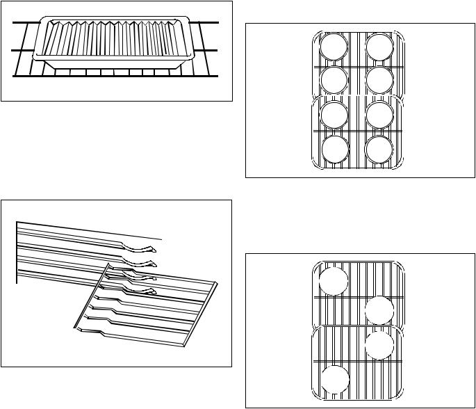
Convection Broiling Rack
Oven includes a special broiling rack. This rack should be placed on top of broiler pan and grid. This allows air to circulate around food and cook evenly without turning. If convection broiling rack is not used, foods must be turned at least once during cooking.
Oven Rack Placement
Position oven rack before turning oven on.
1.Pull rack forward to stop position.
2.Raise front edge of rack and pull until rack is out of oven.
3.Place rack in new rack position.
•Curved edge of rack must be toward rear of oven.
Spacesaver™ Convection Rack
Spacesaver™ convection rack sets 1/2" off the oven floor when in lowest rack postion to allow air to circulate around food and cook evenly. This rack provides more usable oven space for cooking large items or several food items at once.
Position oven rack before turning oven on. To remove rack:
1.Pull rack forward to stop position.
2.Raise front edge of rack and pull until rack is out of oven.
3.Place rack in new rack position.
•Curved edge of rack must be toward rear of oven.
Convection Pan Placement
Baking pans and cookie sheets should not touch side or rear walls of oven. If pans are placed on different racks, they can be placed directly over each other. Convection cooking circulates air around oven providing even browning on all rack positions. When using convection, oven can be loaded on all racks with excellent cooking results.
Pan Placement
•Keep pans and cookie sheets 2 inches from oven walls.
•Stagger pans placed on different racks so one is not directly over the other.
Slo-Cook™ Roasting Rack
Oven includes a Slo-Cook™ roasting rack. This rack should be placed in pan or roaster. Slo-Cook™ roasting rack elevates food keeping it out of grease and fat.
©2003 Maytag Appliances Company |
16021875 Rev. 0 |
7 |
General Information
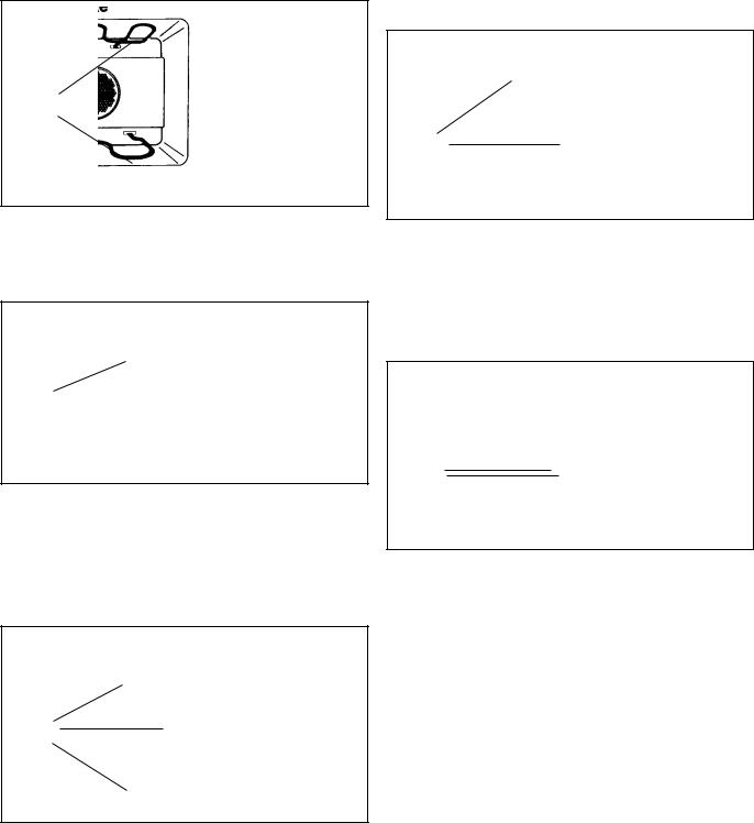
Removing Oven Door
The oven door can be removed for ease in cleaning large spills.
!CAUTION
To avoid personal injury or property damage, handle oven door with care. Door is heavy and can be damaged if dropped.
Do not place hands in hinge area when door is removed. Hinge can snap closed and pinch your hands.
Door contains tempered glass. If glass is scratched, chipped, impacted or twisted it may break suddenly. If door glass appears damaged it should be replaced immediately.
1.Open door to first stop.
2.Remove screws in door liner.
3.Grasp door firmly on each side and lift it upward off hinges. Do not push hinges closed once oven door is removed.
• Do not lift door using door handle.
remove
screw here remove
 screw here
Replacing Oven Door
1.Make sure the hinges are open to the first stop position. If hinges have been accidentally closed, carefully pull them open to first stop. Align door with hinge arms.
2.Slide door down and into place. Be sure door is completely down on hinges.
3.Replace screws in door liner.
Replacing Oven Light
Protective gloves must be worn when changing light bulb.
1.Disconnect electrical supply by turning off power at fuse box.
2.Remove oven door.
3.Remove light cover by inserting a screwdriver, blade end covered in masking tape, into slot at front of lens cover and prying lens cover downward.
4.Unscrew bulb from receptacle.
•Replacement bulbs are available through your local Amana service or parts center.
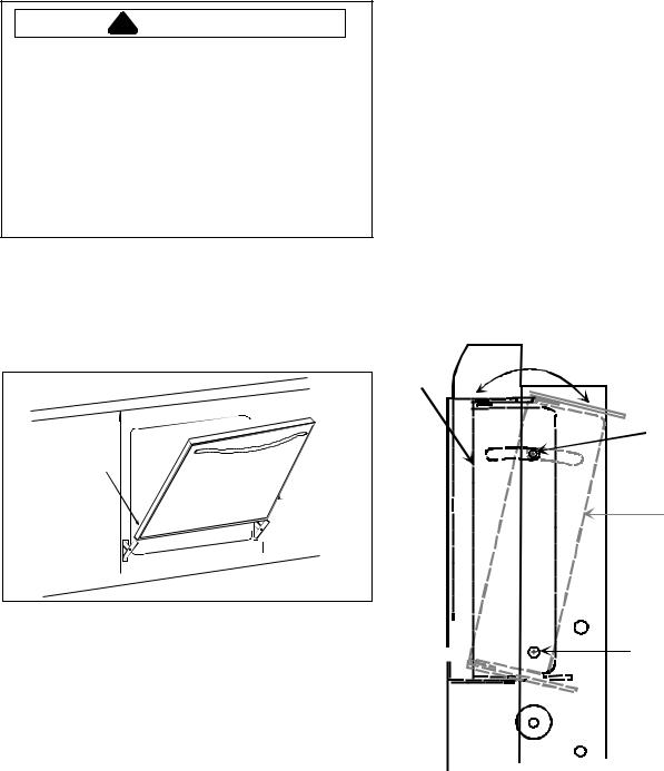
Tilting Control Panel
Control panel can be adjusted to tilt from 0° to 12° to make more visible.
1.Loosen screws on top, and sides of control panel and pivot screw on bottom, sides of control panel before installing oven, or while oven partially pulled from opening.
2.Adjust control panel to desired angle and retighten screws.
0° tilt
Loosen screw
12° tilt
Pivot screw
8 |
16021875 Rev. 0 |
©2003 Maytag Appliances Company |
Care and Cleaning
Cleaning Oven Parts
Oven Part |
Cleaning Materials |
General Directions |
Broil element |
|
Do not clean broil element. Any soil will |
|
|
burn off during cooking. |
Broiler pan and grid |
Soap, a nonabrasive plastic scouring |
Drain fat. Cool pan and grid slightly. (Do |
|
pad and water |
not let soiled pan and grid stand in oven |
|
|
to cool.) Sprinkle with soap. Fill pan with |
|
|
warm water. Let pan and and grid stand |
|
|
for a few minutes. Wash and scour if |
|
|
necessary. Rinse and dry. Broiler pan and |
|
|
grid may also be cleaned in the |
|
|
dishwasher. |
Interior oven door, outside |
Soap and water |
Cool before cleaning. Frequent wiping |
door gasket |
|
with mild soap and water will prolong the |
|
|
time between major cleanings. Be sure to |
|
|
rinse thoroughly. For extra dried on soil a |
|
|
mild abrasive can be used. Never use |
|
|
strong abrasives, gritty cleaners, |
|
|
commercial oven cleaners or steel wool. |
Oven door gasket |
Do not clean |
Gaskets should not be cleaned. Care |
|
|
should be taken not to wet or rub the |
|
|
gasket. |
Oven racks |
Soap and water |
For heavy soil, clean by hand and rinse |
|
|
thoroughly. Remove oven racks for ease |
|
|
in cleaning. |
Outside of oven |
Soap and water |
Wash all glass with cloth dampened in |
|
|
soapy water. Rinse and polish with a dry |
|
|
cloth. Do not use cleaning products |
|
|
containing ammonia. |
©2003 Maytag Appliances Company |
16021875 Rev. 0 |
9 |

Component Testing Information
!WARNING
To avoid risk of electrical shook, personal injury or death: disconnect power to oven before servicing, unless testing requires it.
Illustration |
Component |
Test Procedure |
Results |
|
|
|
Oven light socket |
Test continuity of receptacle terminals. |
Indicates continuity with bulb screwed in. |
|
|
|
Measure voltage at oven light. |
120 VAC, see wiring diagram for terminal |
|
|
|
|
identification. |
|
|
|
|
If no voltage is present at oven light |
|
|
|
|
check wiring. |
|
|
Bake element |
Test continuity of terminals. |
Indicates continuity. |
|
|
|
Test voltage to terminals. |
240 VAC |
|
|
Broil element |
Test continuity of terminals. |
Indicates continuity. |
|
|
|
Test voltage to terminals. |
240 VAC |
|
|
Convection element |
Test continuity of terminals. |
Indicates continuity. |
|
|
|
Test voltage to terminals. |
240 VAC |
|
|
Convection motor fan |
Verify supply voltage. |
120 VAC |
|
|
|
Check continuity of terminals, and |
Continuity |
|
|
|
verify terminals are not shorted to |
Convection fan will stay ON, when |
|
|
|
chassis. |
|
|
|
|
|
oven door is opened. |
|
|
Blower motor |
Verify supply voltage. |
120 VAC |
|
|
|
Check continuity of terminals, and |
Continuity |
|
|
|
verify terminals are not shorted to |
|
|
|
|
chassis. |
|
|
|
Heraeus sensor |
Measure resistance. |
Approximately 1100 Ω at room |
|
|
|
|
temperature 75ºF. |
|
|
Hinge |
Carefully open the hinge fully, and |
|
|
|
|
insert a wooden dowel or screwdriver |
! CAUTION |
Opening |
|
bit into opening. |
Do not place hands in hinge area when |
|
|
Remove top and bottom screws |
|||
|
oven door is removed. Hinge can snap |
|||
|
|
|
securing hinge. |
|
|
|
|
closed and pinch hands or fingers. |
|
|
|
|
Slide hinge top towards rear of unit |
|
|
|
|
|
|
|
|
|
and guide hinge out through frame |
|
|
|
|
opening or storage drawer. |
|
|
|
Door lock switch |
Switch connection in following |
COM-NO=Open, COM-NC=Closed |
|
|
|
positions: |
|
|
NC |
|
Unlocked |
COM-NO=Closed, COM-NC=Open |
|
NO |
|
Locked |
|
|
COM |
|
|
|
|
|
Controls |
Verify proper operation. |
|
|
|
|
31–308417–02–0 Fan control |
Open at 115°F, Closes at 155°F |
|
|
|
31–31751801–0 Control limit |
Open at 260°F, Closes at 220°F |
|
|
Door plunger switch |
Remove switch from unit and measure |
|
|
|
|
the following points: |
|
|
|
|
C-NC |
Plunger in infinite, Plunger out continuity. |
C |
NC |
|
C NO |
Plunger in continuity, Plunger out infinite. |
|
NO |
|
|
|
10 |
16021875 Rev. 0 |
©2003 Maytag Appliances Company |
Component Testing Information
!WARNING
To avoid risk of electrical shook, personal injury or death: disconnect power to oven before servicing, unless testing requires it.
ERC mylar touch system
AOES3030
|
HR |
|
P |
3 5 0 ° |
+ |
TIMER |
STOP |
|
|
|
LIGHT |
: |
ER |
TIME |
BAKE |
BROIL CLEAN |
|||||
|
|
|
BROIL |
O |
ON / OFF |
|
|
|||
|
|
|
|
DELAY BAKE |
N |
|
|
|
|
|
OVEN |
DELAY BAKE CLN STOP TIME |
|
CLEAN LOCKED |
- |
|
COOK |
|
|
||
TIME CONTROL |
|
CLOCK |
|
|
||||||
CANCEL |
|
TIME |
OVEN CONTROL |
|||||||
|
|
|
||||||||
AOCS3040
|
|
|
AM |
|
HR |
|
|
|
|
P |
|
TIMER |
STOP |
|
|
|
|
|
|
|
CONV |
|
CONV |
|
|
||
|
|
|
|
: |
|
|
° ER 3 5 0 |
+ |
|
|
BAKE |
|
|
|
|
|
|
||||||||||
|
|
LIGHT |
|
|
|
|
|
|
|
|
ON / OFF |
TIME |
|
|
BROIL |
CONV |
CLEAN |
|
|||||||||
|
|
|
PM |
|
|
|
|
|
|
|
CONV BR OIL PRE- |
|
|
|
|
|
|
|
|
BAKE |
|
BROIL |
|
|
|||
|
|
|
|
|
|
|
|
|
|
|
DELAY TIMED BAKE |
|
|
|
|
|
|
THERMAL |
|
|
|
|
CONVECTION |
|
|
|
|
|
|
|
CLEAN OVEN |
|
|
|
|
|
|
|
|
|
|
|
|
|
|||||||||||
|
|
|
|
STOP ON TIMER CLEAN LOCK ON |
|
|
COOK |
|
|
|
|
|
|
|
|
|
|
||||||||||
|
|
OVEN |
|
|
|
|
|
|
|
|
- |
CLOCK |
|
|
|
|
|
|
|
|
|
|
|
|
|
||
|
CANCEL |
TIME CONTROL |
TIME |
|
|
|
|
|
MULTI-MODE OVEN |
|
|
||||||||||||||||
|
|
|
|
|
|
|
|
|
|
||||||||||||||||||
|
|
|
|
|
|
|
|
|
|
|
|
|
|
|
|
|
|
|
|
|
|
|
|
|
|
||
|
|
|
|
|
|
|
|
|
|
|
|
|
|||||||||||||||
Illustration |
|
Component |
|
Test Procedure |
|
|
|
|
|
|
|
Results |
|||||||||||||||
See illustrations |
|
Mylar touch system |
F1 - Control malfuction. |
|
|
|
|
|
Replace ERC. |
||||||||||||||||||
above. |
|
ERC4800 |
|
|
|
|
|
F2 - Oven over temperature. |
|
|
|
|
|
Check sensor wiring, sensor , and |
|||||||||||||
|
|
|
|
|
|
|
|
|
|
|
|
F3 - Open sensor or sensor circuit. |
|
temperature limiter. |
|||||||||||||
|
|
|
|
|
|
|
|
|
|
|
|
|
Check sensor resistance and wiring. |
||||||||||||||
|
|
|
|
|
|
|
|
|
|
|
|
F4 - Shorted sensor or sensor circuit. |
|
Check sensor resistance and wiring. |
|||||||||||||
|
|
|
|
|
|
|
|
|
|
|
|
F7 - Shorted input key. |
|
|
|
|
|
Verify glass to adaptor board connection, |
|||||||||
|
|
|
|
|
|
|
|
|
|
|
|
F9 - Door lock or door lock circuitry |
|
replace glass panel. |
|||||||||||||
|
|
|
|
|
|
|
|
|
|
|
|
|
Check latch switch. |
||||||||||||||
|
|
|
|
|
|
|
|
|
|
|
|
malfuction. |
|
|
|
|
|
|
|
|
|
|
|
|
|
|
|
|
|
|
|
|
|
|
|
|
|
|
|
FF - door lock circuitry malfuction at |
|
Check latch switch and door motor. |
|||||||||||||
|
|
|
|
|
|
|
|
|
|
|
|
clean temperature. |
|
|
|
|
|
|
|
|
|
||||||
|
|
|
|
|
|
|
|
|
|
|
|
DOOR - Lock status is not sensed |
|
Verify operation of door latch switches. |
|||||||||||||
|
|
|
|
|
|
|
|
|
|
|
|
within 90 seconds of energizing door |
|
|
|
|
|
||||||||||
|
|
|
|
|
|
|
|
|
|
|
|
lock relay. |
|
|
|
|
|
|
|
|
|
|
|
|
|
|
|
ERC4800 Controlled |
|
Oven temperature |
Press BAKE. |
|
|
|
|
|
|
|
|
|
|
While increasing or decreasing oven |
|||||||||||||
|
|
adjustment |
Press + slew pad until an oven |
|
temperature, this does not affect self- |
||||||||||||||||||||||
|
|
|
|
|
|
|
|
|
|
|
|
temperature greater than 500° shows |
|
cleaning temperature. |
|||||||||||||
|
|
|
|
|
|
|
|
|
|
|
|
on display. |
|
|
|
|
|
|
|
|
|
|
|
|
|
|
|
|
|
|
|
|
|
|
|
|
|
|
|
Immediately press and hold BAKE |
|
|
|
|
|
||||||||||
|
|
|
|
|
|
|
|
|
|
|
|
until “00” appears in display, |
|
|
|
|
|
|
|
|
|
||||||
|
|
|
|
|
|
|
|
|
|
|
|
approximately 5 seconds. |
|
|
|
|
|
|
|
|
|
||||||
|
|
|
|
|
|
|
|
|
|
|
|
To decrease oven temperature (for a |
|
|
|
|
|
||||||||||
|
|
|
|
|
|
|
|
|
|
|
|
cooler oven), press - slew pad until |
|
|
|
|
|
||||||||||
|
|
|
|
|
|
|
|
|
|
|
|
negative numbers appear.Oven can |
|
|
|
|
|
||||||||||
|
|
|
|
|
|
|
|
|
|
|
|
be adjusted from -5 to -35 degrees |
|
|
|
|
|
||||||||||
|
|
|
|
|
|
|
|
|
|
|
|
lower. To avoid overadjusting oven |
|
|
|
|
|
||||||||||
|
|
|
|
|
|
|
|
|
|
|
|
move temperature -5 degrees each |
|
|
|
|
|
||||||||||
|
|
|
|
|
|
|
|
|
|
|
|
time. |
|
|
|
|
|
|
|
|
|
|
|
|
|
|
|
|
|
|
|
|
|
|
|
|
|
|
|
To increase oven temperature (for |
|
|
|
|
|
||||||||||
|
|
|
|
|
|
|
|
|
|
|
|
warmer oven), press + slew pad until |
|
|
|
|
|
||||||||||
|
|
|
|
|
|
|
|
|
|
|
|
positive numbers appear. Oven can be |
|
|
|
|
|
||||||||||
|
|
|
|
|
|
|
|
|
|
|
|
adjusted 5 to 35 degrees higher. To |
|
|
|
|
|
||||||||||
|
|
|
|
|
|
|
|
|
|
|
|
avoid overadjusting oven move |
|
|
|
|
|
||||||||||
|
|
|
|
|
|
|
|
|
|
|
|
temperature 5 degrees each time. |
|
|
|
|
|
||||||||||
|
|
|
|
|
|
|
|
|
|
|
|
Press OVEN CANCEL. Temperature |
|
|
|
|
|
||||||||||
|
|
|
|
|
|
|
|
|
|
|
|
adjustment will be retained even |
|
|
|
|
|
||||||||||
|
|
|
|
|
|
|
|
|
|
|
|
though power failure. |
|
|
|
|
|
|
|
|
|
||||||
ERC4800 Controlled |
|
Twelve hour off |
Control will automatically cancel any |
|
|
|
|
|
|||||||||||||||||||
|
|
|
|
|
|
|
|
|
|
|
|
cooking operation and remove all relay |
|
|
|
|
|
||||||||||
|
|
|
|
|
|
|
|
|
|
|
|
drives 12 hours after the last pad |
|
|
|
|
|
||||||||||
|
|
|
|
|
|
|
|
|
|
|
|
touch. |
|
|
|
|
|
|
|
|
|
|
|
|
|
|
|
©2003 Maytag Appliances Company |
16021875 Rev. 0 |
11 |
Component Testing Information
!WARNING
To avoid risk of electrical shook, personal injury or death: disconnect power to oven before servicing, unless testing requires it.
|
|
Illustration |
Component |
Test Procedure |
Results |
||||||||||||||||
ERC4800 Controlled |
Child lock out |
This is a safety feature that can be |
|
||||||||||||||||||
|
|
|
|
|
|
|
|
|
|
|
|
|
|
|
|
|
|
|
|
used to prevent children from |
|
|
|
|
|
|
|
|
|
|
|
|
|
|
|
|
|
|
|
|
|
accidentally programming the oven. It |
|
|
|
|
|
|
|
|
|
|
|
|
|
|
|
|
|
|
|
|
|
disables the electronic oven control. |
|
|
|
|
|
|
|
|
|
|
|
|
|
|
|
|
|
|
|
|
|
Press and hold Bake and Cook Time |
|
|
|
|
|
|
|
|
|
|
|
|
|
|
|
|
|
|
|
|
|
for 10 seconds. “OFF” will display |
|
|
|
|
|
|
|
|
|
|
|
|
|
|
|
|
|
|
|
|
|
where the temperature normally |
|
|
|
|
|
|
|
|
|
|
|
|
|
|
|
|
|
|
|
|
|
appears. |
|
|
|
|
|
|
|
|
|
|
|
|
|
|
|
|
|
|
|
|
|
To reactivate the control, press and |
|
|
|
|
|
|
|
|
|
|
|
|
|
|
|
|
|
|
|
|
|
hold Bake and Cook Time for 10 |
|
|
|
|
|
|
|
|
|
|
|
|
|
|
|
|
|
|
|
|
|
seconds. Child lockout features must |
|
|
|
|
|
|
|
|
|
|
|
|
|
|
|
|
|
|
|
|
|
be reset after a power failure. |
|
|
|
|
|
|
|
|
|
|
|
|
|
|
|
|
|
|
|
|
Relay board |
Listen for relay to actuate. |
If relay does not actuate, verify power to |
|
|
|
|
|
|
|
|
|
|
|
|
E1 |
|
|
|
|
Verify input and output power. |
relay. |
|||
|
|
|
|
|
|
|
|
|
|
|
|
|
|
|
|
||||||
|
|
|
|
|
|
|
|
|
|
|
|
|
|
|
|
|
|
|
|
||
|
|
|
|
|
|
|
|
|
|
|
|
|
|
|
|
|
|
|
|
||
|
|
|
|
|
|
|
|
|
|
|
|
|
|
|
|
|
E3 |
|
|||
|
|
|
|
|
|
|
|
|
|
|
|
|
|
|
|
|
|
|
|
|
|
|
|
|
|
|
|
|
|
|
|
|
|
|
|
|
|
|
|
|
|
|
|
|
|
|
|
|
|
|
|
|
|
|
|
|
|
|
|
|
E2 |
|
|
|
|
|
|
|
|
|
|
|
|
|
|
|
|
|
|
|
|
|
|
|
|
|
|
|
|
|
|
K10 |
K11 |
|
|
|
|
|
|
||||||||||
|
|
|
|
|
|
|
|
|
|
|
|
|
|
|
|
|
|||||
|
|
|
|
|
|
|
|
|
|
|
E14 |
|
|
|
|||||||
E17 |
|
|
|
|
|
|
|
|
|
|
|||||||||||
Oven |
|
|
|
|
|
|
Panel |
|
|
|
|
||||||||||
|
|
|
|
Light |
|
|
|
|
|
|
Light |
|
|
|
|
|
|
|
|||
E16 |
|
|
|
|
|
|
|
|
|
|
|
|
|
||||||||
|
|
|
|
|
|
|
|
E15 |
|
|
|
||||||||||
|
|
|
|
|
|
|
|
|
|
|
|
|
|
|
|
|
|
|
|
||
|
|
|
|
|
|
|
|
|
|
|
|
|
|
|
|
|
|
|
|
|
|
|
|
|
|
K4 |
|
|
|
|
|
|
K2 |
|
|
|
|
|
|
||||
|
|
|
|
|
|
|
|
|
|
|
|
|
|
||||||||
|
|
|
|
|
|
|
|
|
|
|
E6 |
|
|
|
|||||||
E11 |
|
|
|
|
|
|
|
|
|
||||||||||||
|
|
|
|
Bake |
|
|
|
|
|
|
Conv. |
|
|
|
|
|
|
||||
|
|
|
|
|
|
|
|
|
|
Element |
|
|
|
|
|
|
|||||
|
E10 |
|
|
|
|
|
|
|
|
|
|
|
|
|
|
|
|
||||
|
|
|
|
|
|
|
|
|
|
|
|
E7 |
|
|
|
||||||
|
|
|
|
|
|
|
|
|
|
|
|
|
|
||||||||
|
K5 |
|
|
|
|
|
|
K3 |
|
|
|
|
|
|
|
||||||
|
|
|
|
|
|
|
|
|
|
|
|
|
|
|
|
||||||
|
|
|
|
|
|
|
|
|
|
|
|
E8 |
|
|
|
||||||
E13 |
|
|
|
|
|
|
|
|
|
|
|||||||||||
|
|
|
|
Broil |
|
|
|
|
|
|
Door |
|
|
|
|
|
|
|
|||
|
|
|
|
|
|
|
|
|
|
Lock |
|
|
|
|
|
|
|
||||
|
|
|
|
|
|
|
|
|
|
|
|
|
|
|
E9 |
|
|
|
|||
E12 |
|
|
|
|
E19 |
|
|
|
|
|
|||||||||||
|
|
|
|
|
|
|
|
|
|
|
|||||||||||
K6 |
|
|
|
|
|
|
|
|
|||||||||||||
|
|
|
|
|
|
|
|
|
|
|
K1 |
|
|
|
|
|
|
|
|||
|
|
|
|
|
|
|
|
|
|
|
|
|
|
|
|
|
|
||||
|
|
|
|
|
|
|
|
|
|
|
|
|
E4 |
|
|
|
|||||
|
|
|
|
Double |
|
|
|
|
|
Conv. |
|
|
|
|
|
|
|
||||
|
|
|
|
Line Brk |
|
|
|
|
|
Fan |
|
|
|
|
|
|
|
||||
|
|
|
|
|
|
|
|
|
|
|
|
|
|
|
|
|
E5 |
|
|
|
|
|
|
|
|
|
|
|
|
|
|
|
|
|
|
|
|
|
|
|
|||
|
|
|
|
|
|
|
|
|
|
|
|
|
|
|
|
|
|
|
|
|
|
E18 |
|
|
|
|
|
|
|
|
|
|
|
|
|
|
|
|
|
|
|||
|
|
|
|
|
|
|
|
|
|
|
|
|
|
|
|
|
|
|
|
|
|
|
|
|
|
|
|
|
|
|
|
|
|
|
|
|
|
|
|
|
ERC/Adapter board |
F1 - Control malfuction. |
Replace ERC. |
|
|
|
|
|
|
|
|
|
|
|
|
|
|
|
|
|
|
|
assembly |
|
|
|
|
|
|
|
|
|
|
|
|
|
|
|
|
|
|
|
|
|
|
|
|
|
|
|
|
|
|
|
|
|
|
|
|
|
|
|
|
|
|
|
|
|
|
|
|
|
|
|
|
|
|
|
|
|
|
|
|
|
|
|
|
|
|
|
|
|
|
|
|
|
|
|
|
|
|
|
|
|
|
|
|
|
|
|
|
|
|
|
|
|
|
|
|
|
|
|
|
|
|
|
|
|
|
|
|
|
|
|
|
|
|
|
|
|
|
|
|
|
|
|
|
|
|
|
|
|
|
|
|
|
|
|
|
|
|
|
|
|
|
|
|
|
|
|
|
|
|
|
|
|
|
|
|
|
|
|
|
|
|
|
|
|
|
|
|
|
|
|
|
|
|
|
|
|
|
Field Selectable Options
Standard: The standard setup is 8. This is a 12 hour type of clock, 60 Hz line frequency and an oven with a convection fan.
Clock Time Format 12 or 24 hour format
The time of day and the stop time can be displayed in either a 12 or 24 hour format. The control will come in a 12 hour format and can be changed to a 24 hour format from the front control panel.
Clock Time Base 60 or 50 Hz input line frequency
This is a time reference for the clock, timer, and internal timing of the control. The control will select the frequency automatically when the control is powered up.
Selecting Options
In order to select the field selectable options, Press and hold the CLOCK pad on power up of the control. To change the options press one of the slew pads until the desired option appears and in approximately 9 seconds the control will change to the normal operation or once selected press the CANCEL pad. The right time digit will indicate the current options selected as listed in the table below. (Standard setting is 8.)
Code Number |
24 Hour Clock |
50 Hz |
No Convection Fan |
8 |
|
|
|
9 |
X |
|
|
H |
|
X |
|
r |
X |
X |
|
o |
|
|
X |
d |
X |
|
X |
− |
|
X |
X |
Blank |
X |
X |
X |
X = indicates Selected = indicates Not Selected
12 16021875 Rev. 0 ©2003 Maytag Appliances Company
Component Testing Information
!WARNING
To avoid risk of electrical shook, personal injury or death: disconnect power to oven before servicing, unless testing requires it.
Element Conditions
Relay drive requirements are defined as a percentage of on time based on a 60 second cycle.
Bake ....................... |
First rise to temperature = 100% bake, 50% broil, then 100% bake, 25% broil |
Broil........................ |
100% broil, 0% bake |
Clean ...................... |
100% broil, 25% bake |
Convection ............ |
First rise to temperature = 100% bake, 50% broil, then 100% Convection element |
|
For convection bake or convection broil refer to bake and broil specifications |
|
|
|
|
Continuity is indicated as 100Ω and below. Each pad must be pressed to perform the following test.
J1-19 |
J1-18 |
J1-16 |
J1-8 |
J1-9 |
J1-10 |
J1-11 |
J1-12 |
J1-13 |
J1-14 |
|
||||||||||||
|
|
|
|
|
|
|
|
|
|
|
|
|
|
|
|
|
|
|
|
|
J1 |
- 2 |
|
|
|
|
|
|
|
BAKE |
|
BROIL |
CLEAN |
|
|
|
|
|
|
|
|||||
|
|
|
|
|
|
|
|
|
|
|
|
|
|
|
|
|
|
|||||
|
|
|
|
|
|
|
|
|
|
|
|
|
|
|
|
|
|
|
|
|
J1 |
- 3 |
|
|
|
|
|
|
|
TIMER |
|
CLOCK |
STOP |
|
OVEN |
|
|
|
|
|
|
||||
|
|
|
|
|
|
|
|
|
|
|
|
|
|
|
|
|
|
|||||
|
|
|
|
|
|
|
|
|
|
|
TIME |
|
LIGHT |
|
|
|
|
|
|
|
J1 |
- 4 |
|
|
|
|
|
|
|
|
|
COOK |
|
|
|
|
|
|
|
|
|
|
|||
|
|
|
|
|
|
|
|
|
|
|
|
|
|
|
|
|
|
|
|
|
||
|
|
|
|
|
|
|
|
|
TIME |
|
|
|
|
|
|
|
|
|
|
|
J1 |
- 5 |
|
|
|
|
|
|
|
|
|
|
|
|
|
|
|
|
|
|
|
|
|
||
|
|
|
|
|
|
|
|
|
|
|
|
|
|
|
|
|
|
|
|
|
J1 |
- 7 |
|
|
|
|
|
CANCEL |
|
|
|
|
|
|
|
|
|
|
|
|
|
||||
|
|
|
|
|
|
|
|
|
|
|
|
|
|
|
|
|
|
|
|
|
||
|
|
|
|
|
|
|
|
|
|
|
|
|
|
|
|
|
|
|
|
|
J1 |
- 6 |
|
|
|
|
|
|
|
|
|
|
|
|
|
|
|
|
|
|
|
|
|
||
|
|
|
|
|
|
|
|
|
|
|
|
|
|
|
|
|
|
|
|
|
J1 |
- 1 |
|
|
|
|
|
|
|
|
|
|
|
|
|
|
|
|
|
|
|
|
|
||
|
|
|
|
|
|
|
|
|
|
|
|
|
|
|
|
|
|
|
|
|
J1 |
- 20 |
|
SLEW |
|
SLEW |
|
|
|
|
|
|
|
|
|
|
|
|
|
|
|
|
|
||
|
|
|
|
|
|
|
|
|
|
|
|
|
|
|
|
|
|
|
|
|
||
|
UP |
|
DOWN |
|
|
|
|
|
|
|
|
|
|
|
|
|
|
|
|
|
||
Switch Matrix for AOES3030
J1-19 |
J1-18 |
J1-16 |
J1-8 |
J1-9 |
J1-10 |
J1-11 |
J1-12 |
J1-13 |
J1-14 |
|
||||||||||||
|
|
|
|
|
|
|
|
|
|
|
|
|
|
|
|
|
|
|
|
|
J1 - 2 |
|
|
|
|
|
|
|
|
BAKE |
|
BROIL |
CLEAN |
CONV |
|
CONV |
|
CONV |
|
|
|||||
|
|
|
|
|
|
|
1 |
|
1 |
|
1 |
|
BAKE |
|
BROIL |
1 |
|
|
|
|
|
|
|
|
|
|
|
|
|
|
|
|
1 |
|
1 |
|
|
|
|
J1 |
- 3 |
||||
|
|
|
|
|
|
|
TIMER |
CLOCK |
STOP |
|
OVEN |
|
PANEL |
|
|
|
|
|||||
|
|
|
|
|
|
|
|
|
|
|
TIME |
|
LIGHT |
|
LIGHT |
|
|
|
|
|
J1 |
- 4 |
|
|
|
|
|
|
|
|
|
COOK |
|
|
|
|
|
|
|
|
|
|
|
||
|
|
|
|
|
|
|
|
|
TIME |
|
|
|
|
|
|
|
|
|
|
|
|
|
|
|
|
|
|
|
|
|
|
1 |
|
|
|
|
|
|
|
|
|
|
|
J1 |
- 5 |
|
|
|
|
|
|
|
|
|
|
|
|
|
|
|
|
|
|
|
|
|
||
|
|
|
|
|
|
|
|
|
|
|
|
|
|
|
|
|
|
|
|
|
J1 |
- 7 |
|
|
|
|
|
CANCEL |
|
|
|
|
|
|
|
|
|
|
|
|
|
||||
|
|
|
|
|
|
|
|
|
|
|
|
|
|
|
|
|
|
|
|
|
||
|
|
|
|
|
|
1 |
|
|
|
|
|
|
|
|
|
|
|
|
|
|
J1 |
- 6 |
|
|
|
|
|
|
|
|
|
|
|
|
|
|
|
|
|
|
|
|
|
||
|
|
|
|
|
|
|
|
|
|
|
|
|
|
|
|
|
|
|
|
|
J1 |
- 1 |
|
|
|
|
|
|
|
|
|
|
|
|
|
|
|
|
|
|
|
|
|
||
|
|
|
|
|
|
|
|
|
|
|
|
|
|
|
|
|
|
|
|
|
J1 |
- 20 |
|
SLEW |
|
SLEW |
|
|
|
|
|
|
|
|
|
|
|
|
|
|
|
|
|
||
|
|
|
|
|
|
|
|
|
|
|
|
|
|
|
|
|
|
|
|
|
||
|
UP |
|
DOWN |
|
|
|
|
|
|
|
|
|
|
|
|
|
|
|
|
|
||
Switch Matrix for AOCS3040
Top
Control
Panel
Bottom
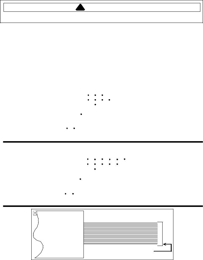
Ribbon Cable
Pin 1 is located at the bottom of the connector.
©2003 Maytag Appliances Company |
16021875 Rev. 0 |
13 |
Testing Procedures
!WARNING
To avoid risk of electrical shock, personal injury or death; disconnect power to unit before servicing.
Oven Door Switch
Clean Safety/Light Switch (Power Off)
1.The switch has NO (normally open), NC (normally closed), and C (common) contacts.
2.Check the switch with an ohmmeter between C and NC with the plunger out. Continuity should exist. With the plunger in, no continuity.
3.Check the switch with an ohmmeter between C and NO with the plunger in. Continuity should exist. With the plunger out, no continuity.
C NC
NO
NOTE: When facing the range, the switch is on the left.
Oven High Limit/Fan Switch
Oven high limit is located on the rear of insulation retainer and connecting to the L2 side of electric supply, this switch is normally closed but will open if external temperature exceeds 260°F or 115°F, see chart below. Fan limit switch is located on the right side of insulation retainer.
|
Part Number |
Open |
Close |
|
|
31751801 |
260°F |
220°F |
|
|
308417 |
115°F |
155°F |
|
|
|
|
|
|
|
|
|
|
|
1.Turn off power to range.
2.Remove oven from wall cutout.
3.Remove screws securing outer cabinet top shield to outer cabinet wrapper shield.
4.Disconnect wires from switch terminal connections.
5.Attach ohmmeter leads to switch terminals. At ambient room temperature (70°F.) continuity should be indicated.
Oven Temperature Sensor
The oven temperature sensor can be checked by using the "Quick Test Mode" covered in this section of manual or detail testing can be accomplished as follows.
The oven temperature sensor is mounted in the oven cavity and electrically connected to the ERC. Following is approximate resistance.
75°F—1082 ohms 350°F—1656 ohms 550°F—2056 ohms 880°F—2686 ohms
Sensor resistance can be checked by removing the sensor interconnect harness plug from the ERC and inserting ohmmeter leads into the harness connector plug. A resistance reading of approximately 1100 ohms should be indicated at ambient room temperature (75°F.). If a higher resistance is indicated then remove sensor from oven, disconnect sensor from harness at plug, and recheck sensor resistance to assure that the problem is in the sensor and not in the interconnect harness or due to a bad connection.
NOTE: Sensor resistance will increase if held in your hand.
Blower Motor
Fan may come on at any time to cool components down.
1.Turn off power to oven.
2.Remove oven from wall cutout.
3.Remove screws securing outer cabinet top shield to outer cabinet wrapper shield.
4.Disconnect wires from motor terminal connectors.
5.Attach ohmmeter leads to terminal tabs on motor.
6.A resistance of ohms should be indicated but may vary with each motor tested. This test is to check the motor winding for an open or shorted winding. If zero or infinite ohms is indicated, the motor winding has failed and the motor must be replaced.
14 |
16021875 Rev. 0 |
©2003 Maytag Appliances Company |
Testing Procedures
!WARNING
To avoid risk of electrical shock, personal injury or death; disconnect power to unit before servicing.
Auto Latch Motor
Do not remove latch motor from latch assembly. If latch motor is defective, replace latch assembly.
1.Disconnect power.
2.Slide oven out from wall cutout approximately 6 inches to gain access to control panel screws.
3.Remove screws securing control panel to unit, and pull control panel out of unit to gain access to latch assembly.
4.Disconnect lead wires from latch motor.
5.Connect jumper cord leads to latch motor.
6.Connect jumper cord to 110 AC power source.
7.Replace if latch motor fails to operate.
8.Reverse procedure to reconnect.
Convection Fan Motor
1.Turn off power to oven.
2.Remove oven from wall cutout.
3.Remove access fan plate to gain access to convection fan motor.
4.Disconnect wires from motor terminal connectors.
5.Attach ohmmeter leads to terminal tabs on motor.
6.A resistance reading of 15-30 ohms should be indicated but may vary with each motor tested. This test is to check the motor winding for an open or shorted winding. If zero or infinite ohms is indicated, the motor winding has failed and the motor must be replaced.
Door Latch Assembly
Auto Latch Switches
Both unlock and lock door latch switches may be replaced.
1.Perform steps 1 through 3, from “Auto Latch Motor”.
2.Disconnect lead wires from door latch switch (unlock).
3.Set ohmmeter to the RX1 scale.
4.Attach meter leads to door latch switch (unlock).
5.Depress actuator arm. The meter should read continuity.
6.Reverse procedure to reconnect.
7.Use the same procedure to test the door latch switch (lock).
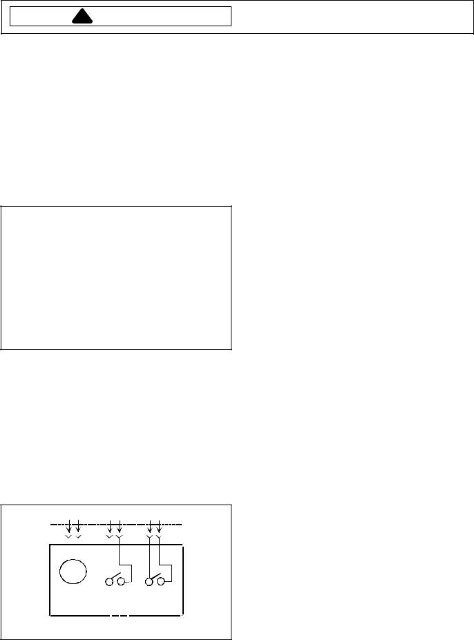
L1 L2 COM NO COM NO
|
M |
|
|
|
|
|
|
|
|
|
|
Unlock |
|
120 VAC |
Lock |
|||||
Switch |
Switch |
|||||
Motor |
||||||
S.P.N.O. |
S.P.N.O. |
|||||
|
|
|
||||
Convection Element Testing
1.Disconnect power to oven.
2.Remove screws securing oven door to hinges and remove door.
3.Remove screws securing fan cover to gain access to convection element.
4.Remove screws securing convection element, and pull gentally outward to gain access to wire terminals.
5.Remove wire connector from element.
6.Attach ohmmeter leads to each of the element terminals. Set ohmmeter to RX1 or RX10 scale.
7.Low ohms or continuity should be indicated.
Broil Element Testing
1.Disconnect power to oven.
2.Remove screws securing oven door to hinges and remove door.
3.Remove screws securing broil element reflector.
4.Gentally pull downward and out to gain access to wire terminals.
5.Remove wire connector from element.
6.Attach ohmmeter leads to each of the element terminals. Set ohmmeter to RX1 or RX10 scale.
7.Low ohms or continuity should be indicated.
Bake Element Testing
1.Disconnect power.
2.Remove oven from wall cutout.
3.Remove screws securing element panel.
4.Remove screws securing element access plate.
5.Remove wire connector from element.
6.Attach ohmmeter leads to each of the element terminals. Set ohmmeter to RX1 or RX10 scale.
7.Low ohms or continuity should be indicated.
Double Switch
©2003 Maytag Appliances Company |
16021875 Rev. 0 |
15 |
 Loading...