


Model PMD325 User Guide
CD Player
R
CLASS 1 LASER PRODUCT
LUOKAN 1 LASERLAITE
KLASS 1 LASERAPPARAT
TEXT
CAUTION |
RISK OF ELECTRIC SHOCK |
DO NOT OPEN |
CAUTION: TO REDUCE THE RISK OF ELECTRIC SHOCK, |
DO NOT REMOVE COVER (OR BACK) |
NO USER-SERVICEABLE PARTS INSIDE |
REFER SERVICING TO QUALIFIED SERVICE PERSONNEL |
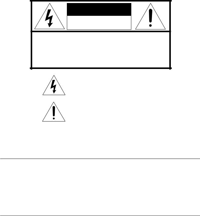
The lightning flash with arrowhead symbol within an equilateral triangle is intended to alert the user to the presence of uninsulated “dangerous voltage” within the product’s enclosure that may be of sufficient magnitude to constitute a risk of electric shock to persons.
The exclamation point within an equilateral triangle is intended to alert the user to the presence of important operating and maintenance (servicing) instructions in the literature accompanying the product.
WARNING
TO REDUCE THE RISK OF FIRE OR ELECTRIC SHOCK, DO NOT EXPOSE THIS APPLIANCE TO RAIN OR MOISTURE.
CAUTION: TO PREVENT ELECTRIC SHOCK, MATCH WIDE BLADE OF PLUG TO WIDE SLOT, FULLY INSERT.
ATTENTION: POUR ÉVITER LES CHOCS ÉLECTRIQUES, INTRODUIRE LA LAME LA PLUS LARGE DE LA FICHE DANS LA BORNE CORRESPON-DANTE DE LA PRISE ET POUSSER JUSQU’AU FOND.
LASER SAFETY
This unit employs a laser. Only a qualified service person should remove the cover or attempt to service this device, due to possible eye injury.
CAUTION : USE OF CONTROLS OR ADJUSTMENTS OR PERFORMANCE OF PROCEDURE OTHER THAN THOSE SPECIFIED HEREIN MAY RESULT IN HAZARDOUS RADIATION EXPOSURE.
IMPORTANT SAFETY
INSTRUCTIONS
READ BEFORE OPERATING EQUIPMENT
This product was designed and manufactured to meet strict quality and safety standards. There are, however, some installation and operation precautions which you should be particularly aware of.
1.Read Instructions – All the safety and operating instructions should be read before the product is operated.
2.Retain Instructions – The safety and operating instructions should be retained for future reference.
3.Heed Warnings – All warnings on the product and in the operating instructions should be adhered to.
4.Follow Instructions – All operating and use instructions should be followed.
5.Cleaning – Unplug this product from the wall outlet before cleaning. Do not use liquid cleaners or aerosol cleaners. Use a damp cloth for cleaning.
6.Attachments – Do not use attachments not recommended by the product manufacturer as they may cause hazards.
7.Water and Moisture – Do not use this product near water-for example, near a bath tub, wash bowl, kitchen sink, or laundry tub, in a wet basement, or near a swimming pool, and the like.
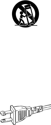
8.Accessories – Do not place this product on an unstable cart, stand, tripod, bracket, or table. The product may fall, causing serious injury to a child or adult, and serious damage to the product. Use only with a cart, stand, tripod, bracket, or table recommended by the manufacturer, or sold with the product. Any mounting of the product should follow the manufacturer’s instructions, and should use a mounting accessory recommended by the manufacturer.
9.A product and cart combination should be moved with care. Quick stops, excessive force, and uneven surfaces may cause the product and cart combination to overturn.
10.Ventilation – Slots and openings in the cabinet are provided for ventilation and to ensure reliable operation of the product and to protect it from overheating, and these openings must not be blocked or covered. The openings should never be blocked by placing the product on a bed, sofa, rug, or other similar surface. This product should not be placed in a built-in installation such as a bookcase or rack unless proper ventilation is provided or the manufacturer’s instructions have been adhered to.
11.Power Sources – This product should be operated only from the type of power source indicated on the marking label. If you are not sure of the type of power supply to your home, consult your product dealer or local power company. For products intended to operate from battery power, or other sources, refer to the operating instructions.
12.Grounding or Polarization – This product may be equipped with a polarized alternating-current line plug (a plug having one blade wider than the other). This plug will fit into the power outlet only one way. This is a safety feature. If you are unable to insert the plug fully into the outlet, try reversing the plug. If the plug should still fail to fit, contact your electrician to replace your obsolete outlet. Do not defeat the safety purpose of the polarized plug.
AC POLARIZED PLUG
13.Power-Cord Protection – Power-supply cords should be routed so that they are not likely to be walked on or pinched by items placed upon or against them, paying particular attention to cords at plugs, convenience receptacles, and the point where they exit from the product.
14.Protective Attachment Plug – The product is equipped with an attachment plug having overload protection. This is a safety feature. See Instruction Manual for replacement or resetting of protective device. If replacement of the plug is required, be sure the service technician has used a replacement plug specified by the manufacturer that has the same overload protection as the original plug.
15.Outdoor Antenna Grounding – If an outside antenna or cable system is connected to the product, be sure the antenna or cable system is grounded so as to provide some protection against voltage surges and built-up static charges. Article 810 of the National Electrical Code, ANSI/NFPA 70, provides information with regard to proper grounding of the mast and supporting structure, grounding of the lead-in wire to an antenna discharge unit, size of grounding conductors, location of antenna-discharge unit, connection to grounding electrodes, and requirements for the grounding electrode. See Figure 1.
16.Lightning – For added protection for this product during a lightning storm, or when it is left unattended and unused for long periods of time, unplug it from the wall outlet and disconnect the antenna or cable system. This will prevent damage to the product due to lightning and power-line surges.
17.Power Lines – An outside antenna system should not be located in the vicinity of overhead power lines or other electric light or power circuits, or where it can fall into such power lines or circuits. When installing an outside antenna system, extreme care should be taken to keep from touching such power lines or circuits as contact with them might be fatal.
18.Overloading – Do not overload wall outlets, extension cords, or integral convenience receptacles as this can result in a risk of fire or electric shock.
19.Object and Liquid Entry – Never push objects of any kind into this product through openings as they may touch dangerous voltage points or short-out parts that could result in a fire or electric shock. Never spill liquid of any kind on the product.
20.Servicing – Do not attempt to service this product yourself as opening or removing covers may expose you to dangerous voltage or other hazards. Refer all servicing to qualified service personnel.
21.Damage Requiring Service – Unplug this product from the wall outlet and refer servicing to qualified service personnel under the following conditions:
a.When the power-supply cord or plug is damaged.
b.If liquid has been spilled, or objects have fallen into the product.
c.If the product has been exposed to rain or water.
d.If the product does not operate normally by following the operating instructions. Adjust only those controls that are covered by the operating instructions as an improper adjustment of other controls may result in damage and will often require extensive work by a qualified technician to restore the product to its normal operation.
e.If the product has been dropped or damaged in any way, and
f.When the product exhibits a distinct change in performance – this indicates a need for service.
22.Replacement Parts – When replacement parts are required, be sure the service technician has used replacement parts specified by the manufacturer or have the same characteristics as the original part. Unauthorized substitutions may result in fire, electric shock, or other hazards.
23.Safety Check – Upon completion of any service or repairs to this product, ask the service technician to perform safety checks to determine that the product is in proper operating condition.
24.Wall or Ceiling Mounting – The product should be mounted to a wall or ceiling only as recommended by the manufacturer.
25.Heat – The product should be situated away from heat sources such as radiators, heat registers, stoves, or other products (including amplifiers) that produce heat.
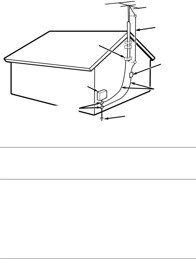
FIGURE 1
EXAMPLE OF ANTENNA GROUNDING AS PER
NATIONAL ELECTRICAL CODE, ANSI/NFPA 70
ANTENNA
LEAD IN
WIRE
GROUND
CLAMP
ANTENNA DISCHARGE UNIT (NEC SECTION 810-20)
ELECTRIC |
GROUNDING CONDUCTORS |
|
SERVICE |
||
(NEC SECTION 810-21) |
||
EQUIPMENT |
||
|
GROUND CLAMPS
POWER SERVICE GROUNDING ELECTRODE SYSTEM
(NEC ART 250, PART H)
NEC - NATIONAL ELECTRICAL CODE
NOTE TO CATV SYSTEM INSTALLER:
This reminder is provided to call the CATV (Cable-TV) system installer's attention to Article 820-40 of the NEC, which provides guidelines for proper grounding and, in particular, specifies that the cable ground shall be connected to the grounding system of the building, as close to the point of cable entry as practical.
NOTE:
This equipment has been tested and found to comply with the limits for a Class B digital device, pursuant to Part 15 of the FCC Rules. These limits are designed to provide reasonable protection against harmful interference in a residential installation. This equipment generates, uses and can radiate radio frequency energy and, if not installed and used in accordance with the instructions, may cause harmful interference to radio communications. However, there is no guarantee that interference will not occur in a particular installation. If this equipment does cause harmful interference to radio or television reception, which can be determined by turning the equipment off and on, the user is encour-
aged to try to correct the interference by one or more of the following measures:
–Reorient or relocate the receiving antenna.
–Increase the separation between the equipment and receiver.
–Connect the equipment into an outlet on a circuit different from that to which the receiver is connected.
–Consult the dealer or an experienced radio/TV technician for help.
NOTE:Changes or modifications may cause this unit to fail to comply with Part 15 of the FCC Rules and may void the user's authority to operate the equipment.
This Class B digital apparatus complies with Canadian ICES-003.
Cet appareil numérique de la Classe B est conforme á la norme NMB-003 du Canada.
FOREWORD
This section must be read before any connection is made to the mains supply.
Warnings
Do not expose the equipment to rain or moisture. Do not remove the cover from the equipment.
Do not insert anything into the equipment through the ventilation holes.
Do not handle the mains lead with wet hands.
Do not cover the ventilation with any items such as tablecloths, newspapers,curtains,etc.
No naked flame sources,such as lighted candles,should be placed on the equipment.
When disposing of used batteries, please comply with governmental regulations or environmental public instruction’s rules that apply in your country or area.
CE marking (only EU version)
This product is in conformity with the EMC directive and low-voltage directive.
EQUIPMENT MAINS WORKING SETTING
Your Marantz product has been prepared to comply with the household power and safety requirements that exist in your area. PMD325 product can be powered by 120 V AC only.
COPYRIGHT
Recording and playback of any material may require consent. For further information refer to the following:
—Copyright Act 1956
—Dramatic and Musical Performers Act 1958
—Performers Protection Acts 1963 and 1972
—any subsequent statutory enactments and orders
INSTALLATION
Remember the following important points when installing the player:
•Do not expose the player to rain or moisture, as this may cause damage to the player.
•All players produce some heat during operation and this heat must be allowed to disperes freely. Do not close any ventilation openings and insure that there is adequate ventilation space behind, beside and above the player.
•Prevent extra heat from reaching the unit. Never put the player in the full glare of the sun or near a heat source.
PRECAUTIONS
The following precautions should be taken when operating the equipment.
GENERAL PRECAUTIONS
When installing the equipment ensure that:
–the ventilation holes are not covered.
–air is allowed to circulate freely around the equipment.
–it is placed on a vibration-free surface.
–it will not be exposed to excessive heat, cold, moisture or dust.
–it will not be exposed to direct sunlight.
–it will not be exposed to electrostatic discharges.
In addition, never place heavy objects on the equipment.
If a foreign object or water does enter the equipment, contact your nearest dealer or service center.
Do not pull out the plug by pulling on the mains lead; grasp the plug. It is advisable when leaving the house for an extended period, or during a thunderstorm, to disconnect the equipment from the mains supply.
PRECAUTIONS IN CONNECTION
•Be sure to unplug the power cable from the AC outlet or turn off the POWER switch before proceeding with any connection.
•Connect one cable at a time observing the “input” and “output”. This will avoid any cross connection between channels and signal inputs and outputs.
•Insert the plugs securely. Incomplete connection may result in noise.
•Prior to connecting other audio and video equipment to the PMD325, please read their owner’s manuals.
ENGLISH
1

CONTENTS
ENGLISH
1. |
BEFORE USING.................................................................................................... |
3 |
2. |
ACCESSORIES ..................................................................................................... |
5 |
3. |
FEATURES ............................................................................................................ |
6 |
4. |
CONNECTIONS .................................................................................................... |
7 |
5. |
NAMES AND FUNCTIONS.................................................................................... |
9 |
|
Front panel ........................................................................................................................................................ |
9 |
|
Display ............................................................................................................................................................ |
10 |
|
Remote control unit ......................................................................................................................................... |
11 |
|
Rear panel ...................................................................................................................................................... |
12 |
6. |
BASIC OPERATIONS .......................................................................................... |
14 |
|
Playing CDs .................................................................................................................................................... |
14 |
|
Playing a specific track ................................................................................................................................... |
15 |
|
Playing a specific part of a specific track ........................................................................................................ |
16 |
7. |
ADVANCED OPERATIONS ................................................................................. |
17 |
|
Repeat play (playing the same tracks repeatedly) .......................................................................................... |
17 |
|
Random play (Playing tracks in a random sequence) .................................................................................... |
18 |
|
AMS play (Searching for a specific track) ....................................................................................................... |
18 |
|
Program play (playing tracks in the preferred sequence) ............................................................................... |
19 |
|
Delete program play (play with undesired tracks skipped) ............................................................................. |
21 |
|
Pitch control (changing the play speed) .......................................................................................................... |
24 |
|
Setting the position to start listening to play (manual cue) ............................................................................. |
25 |
8. |
SETTING THE PLAY FUNCTIONS ..................................................................... |
26 |
|
Using EASY JOG ............................................................................................................................................ |
26 |
|
Various play functions (play modes) ............................................................................................................... |
28 |
9. |
OTHER FUNCTIONS .......................................................................................... |
38 |
|
Last memory ................................................................................................................................................... |
38 |
|
CD-TEXT ........................................................................................................................................................ |
38 |
|
CD-R/RW disc play ......................................................................................................................................... |
39 |
|
MP3 ................................................................................................................................................................ |
39 |
|
Fader start ...................................................................................................................................................... |
42 |
|
How to use the RS-232C connector ............................................................................................................... |
43 |
|
Installing the rack-mounting kit ....................................................................................................................... |
44 |
10. SPECIFICATIONS AND DIMENSIONS ............................................................... |
45 |
|
11. |
TROUBLESHOOTING......................................................................................... |
46 |
2
1. BEFORE USING
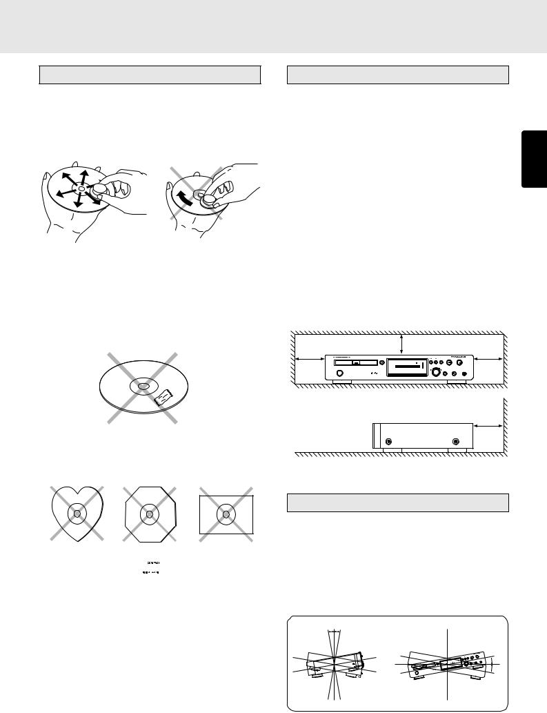
Notes about the discs
*Handle the discs carefully so as not to scratch their surfaces.
*Keep the surfaces of the discs clean at all times.
When cleaning the surfaces of discs, always be sure to use the special cleaner and wipe the surfaces in the directions shown in the figure below.
• Wipe the surface radially |
• Do not wipe the surface in |
from the center. |
the circumferential direction. |
*Do not attach pieces of paper or stickers to the label surfaces of the discs.
When a disc has a piece of plastic tape or rental CD label with paste protruding from the edge or when a disc still bears traces of sticky tape or adhesive labels, do not attempt to play it. If such a disc is played on the CD player, you may find that you cannot remove it or that some other kind of malfunctioning may occur.
*Do not use discs which come in special shapes.
Do not attempt to play heart-shaped or octagonal discs or discs with any other special shapes. You may find that you cannot remove them or that some other kind of malfunctioning may occur in the player.
Inappropriate places for installation
To keep your player in perfect working order for the longest possible time, avoid installing the player in the following locations.
•Wherever it will be exposed to direct sunlight
•Wherever it will be close to a heater or other heat-radiating appliance
•Wherever the humidity is high or ventilation is poor
•Wherever it is very dusty
•Wherever it will be subject to vibration
•On top of a rickety stand or in an unstable location which is tilted at an angle
•On top of an amplifier or other component which dissipates a great deal of heat
•In an audio rack with little space at the top and bottom or other location where the heat dissipation will be obstructed To ensure proper heat dissipation, install the player while leaving clearances between the player and wall or other components, as shown in the figure below.
2 cm or more |
|
10 cm or more |
|
10 cm or more |
|
|
|
|
STOP |
CUE |
PLAY/PAUSE |
— |
+ |
|
|
|
EASY JOG |
|
|
POWER ON/OFF |
|
|
|
|
|
- |
+ |
5 cm or more
ENGLISH
*Use discs which satisfy the CD standards such as those with the “CD logo” or “
 ” mark on their disc label
surfaces.
No guarantees are made for playback if discs which do not satisfy the appropriate CD standards are used. Similarly, no guarantees are made for their sound quality even if it is possible to play such discs.
*To protect your discs from damage, avoid placing them in the following locations.
•Where they will be exposed to direct sunlight or where they will be close to a heater or other heat-radiating appliance
•Where the humidity level is high or it is very dusty
•Near a window or other such location where they may be exposed to rain
*Get into the habit of putting the discs back in their cases after use.
Installation precautions
In order to ensure that the unit will operate correctly, install and operate it within +/-10 degrees from the horizontal plane. If the unit tilts too far in one direction, its disc may be pinched or it may not be possible to open and close the disc holder properly.
When the unit is to be installed in a 19-inch rack for use, secure it firmly in four places.
Refer to page 45 for the outline drawing.
10°10°
 10° 10°
3

ENGLISH
BEFORE USING
Do not place objects on top
• Refrain from placing any objects on top of the player.
Cautions on handling power cord
•Do not touch the power cord with wet hands.
•When disconnecting the power cord, always make sure that you take hold of the plug. Yanking out or bending the cord can damage it and/or cause electric shocks or a fire.
•Get into the habit of disconnecting the power plug before leaving home.
Do not attempt repairs yourself
•Refrain from lubricating the player: doing so can cause malfunctioning.
•Only qualified engineers with specialized expertise are authorized to repair the pick-up and parts inside the player.
Precautions
•In winter, droplets of water form on the insides of the windows of a heated room: this is called condensation. This CD player uses an optical lens, so the condensation may form in the following cases.
-In a room immediately after the heating has been turned on
-In a room where the humidity level is high
-When the player has been suddenly brought from a cold location into a warm room
Since, in cases like this, the track numbers may not be read and the player is prevented from operating properly, wait about 30 minutes, and then operate the player.
•This player may cause interference on a tuner or TV set. If this is the case, place it further away from the tuner or TV set.
•Compact discs have much less noise than analog records and hardly any noise is heard before play starts. Bear in mind, therefore, that if the volume control on the amplifier is set too high, you will risk damaging other audio components.
•This player is designed to play music CDs only. It cannot play CD-ROMs used with personal computers, game CDs, video CDs or DVDs (video/audio).
Cautions on handling batteries
Misuse of the batteries can result in electrolyte leakage, rupturing, corrosion, etc.
Bear in mind the following points when using batteries.
•Remove the batteries from the remote control unit if the unit is not going to be used for a prolonged period (a month or more).
•Do not use an old battery together with a new one.
•Insert the batteries while ensuring that their  and
and  poles are properly aligned with the corresponding markings on
the remote control unit.
•Batteries with the same shape may have different voltages. Do not use different types of batteries together.
•If electrolyte has leaked, thoroughly wipe the inside of the battery compartment, and then insert new batteries.
4
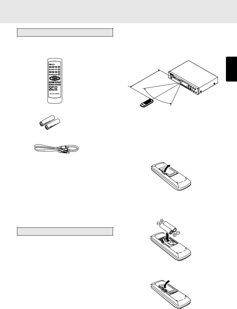
2. ACCESSORIES
Checking the accessories
After opening the cover of the packing box, check that the following accessories are included.
• Remote control unit (RC7300CD)
OPEN/CLOSE |
DISPLAY |
|
|
1 |
2 |
3 |
REPEAT |
4 |
5 |
6 |
AMS |
7 |
8 |
9 |
RANDOM |
PROGRAM |
0 |
CANCEL |
A-B |
|
|
|
TIME |
TEXT |
MENU |
ENTER |
SCROLL/ |
RECALL |
|||
INDEX - |
INDEX + |
Q. REPLAY |
|
- |
PITCH |
+ |
|
|
RESET |
|
|
REMOTE CONTROLLER
RC7300CD
•Size “AA” batteries x 2
•Audio connecting cord (1 meter long)
•User Guide
•Warranty card
Usage of REMOTE CONTROL UNIT
•Precautions
-Do not allow direct sunlight, an inverter fluorescent light or other strong source of light to shine onto the player’s infrared signal reception window (remote sensor). Otherwise, the operation of the remote control unit may be disabled.
-Bear in mind that operating the remote control unit may cause other devices operated by infrared rays to be operated by mistake.
-The remote control unit cannot be operated if the space between the controller and the player’s remote sensor is obstructed.
-Do not place any objects on top of the remote control unit. Doing so may cause one or more buttons to be held down which will cause the batteries to run down.
• Operational range
As shown in the figure below, the player can be operated by the remote control unit in a range which of about 5 meters from the player’s remote sensor and over an angle up to 30 degrees to the left and 30 degrees to the right of the position directly in front.
5m |
ENGLISH |
60°
• Loading batteries
Before using the supplied remote control unit for the first time, load the batteries in the remote control unit. The batteries provided are used to verify the operations of the remote control unit only.
1Take hold of the tab on the battery cover which is found on the back side of the remote control unit, and pull it up.
2Load the two new size “AA” batteries inside the battery compartment while taking care to align their polarities
correctly with the polarity markings ( with
with  and
and  with
with  ).
).
Size “AA” (SUM-3) batteries x 2
3Push the battery cover down in the direction of the arrow to close it.
5

3. FEATURES
ENGLISH
•Play of unfinalized CD-R and CD-RW discs supported
The PMD325 can play even partially once-written CD-R and CD-RW discs that could not be played by conventional CD players. Since unfinalized discs which have some recording time left can be played, even partially edited discs can be played.
•MP3 play and ID3 tag display supported
The PMD325 supports not only the play of CD-R and CDRW discs recorded with MP3 files but also the ID3 tags which are the text information of MP3 files so that text giving the track information or artists’ names can be displayed. (Japanese characters cannot be displayed.)
•CD-TEXT displays supported
•Pitch control function
The PMD325 comes with a pitch control function that enables the play speed (pitch) to be varied in a -12% to +12% range. This is useful when practicing to play a musical instrument.
•Quick replay function
By means of a single-touch action, the quick replay function returns play to a position, which is a number of seconds (setting range: 1 to 30 seconds) that has been set, before the position of the track now playing. This enables you to return and listen again to the section a little before the position where the track is now playing.
•End monitor function
By means of a single-touch action, the end monitor function plays the end part of the track now playing for the duration (setting range: 1 to 30 seconds) which has been set. This makes it easy to check the end part of the track which is now being played.
•Auto cue function
This enables play to start automatically from the position where the sound begins.
•Manual cue function
By setting the play start position in advance, play can always be started at the preset position.
•End warning function
When the end of the track being played is approached, the end warning indicator starts flashing to signal that the end of the track now playing is near.
•Wide range of play modes
Among the many play modes featured by the PMD325 are single play (STOP, NEXT, RECUE), programmed play, repeat play (ALL, 1-track, A-B) and auto pause.
•External control interfaces
The PMD325 features RS-232C, parallel control I/O and remote I/O as external control interfaces.
•Timer play supported
•CS4396 high-performance D/A converter (made by Cirrus Logic)
High-linearity play is achieved by oversampling the PCM signals to 128fs inside the D/A converter and combining dynamic element matching (DEM) with multi-element switched capacitors.
•Digital and analog areas configured separately
The digital area consisting of the servo, decoder and microcomputer circuitry is mounted en bloc on the CD mechanism PCB away from the analog (audio circuitry) area.
This keeps out the pulsive noise generated from the digital area and yield a pure sound reproduction.
6
4. CONNECTIONS
This CD player is connected to an amplifier, CD recorder and other components for use. To ensure that the components are connected properly, refer to the instruction manuals that come with the components to be connected.
Before connecting the components, be absolutely sure to turn off their power.
Connecting to an amplifier
•Connecting the analog unbalanced output connectors
Use the audio connecting cord to connect the player with a stereo amplifier or AV amplifier. Do not connect the player to the PHONO input connectors on the amplifier.
When making the connections, insert the plugs securely into the connectors. Failure to insert the plugs securely may result in noise.
BALANCED |
|
|
|
|
|
|
R |
L |
|
|
|
|
|
OUTPUT LEVEL |
|
CONTROL I/O |
RS232C |
|
|
|
|
|
|
|
|
|
|
L |
|
|
IN |
|
|
|
|
|
|
|
|
DIGITAL OUT |
|
|
|
|
|
|
(SPDIF) |
|
R |
|
|
OUT |
|
CONNECTION |
|
|
|
|
|
|
1 |
GND |
|
|
|
EXTERNAL |
INTERNAL |
3 |
HOT (+) |
|
COAX. |
OPT. |
2 1 2 |
|||
ANALOG OUT |
DIGITAL OUT |
REMOTE CONTROL |
3 |
COLD (-) |
||
(Red) 


 (White)
|
Audio connecting cord (supplied) |
|
|||
(Red) |
(White) |
|
|
Signal flow |
|
|
|
|
|
||
|
|
|
|
|
R |
PHONO |
|
|
|
|
|
GND |
|
|
|
|
SPEA |
|
|
|
|
|
|
|
|
|
|
|
S P E A K E R S I M P E |
L |
|
|
L |
L |
IN |
R |
|
|
R |
R |
OUT |
PHONO |
CD TUNER AUX |
PLAY REC |
PLAY REC |
PRE OUT |
REMOTE |
|
/DVD |
CD-R |
MD/TAPE |
||
|
|
CONTROL |
|||
Amplifier
•Connecting the ANALOG BALANCED OUT (analog balanced output) connectors
Connect the unit to the stereo amplifier or AV amplifier using XLR connector cables.
When making the connections, insert the plugs firmly into the connectors. Failure to insert them securely gives rise to noise.
BALANCED |
|
|
|
|
|
ENGLISH |
R |
L |
|
|
|
|
|
OUTPUT LEVEL |
|
CONTROL I/O |
RS232C |
|
|
|
|
|
|
|
|
|
|
L |
|
|
IN |
|
|
|
|
|
|
|
|
DIGITAL OUT |
|
|
|
|
|
|
(SPDIF) |
|
R |
|
|
OUT |
|
CONNECTION |
|
|
|
|
|
|
1 |
GND |
|
|
|
EXTERNAL |
INTERNAL |
3 |
HOT (+) |
|
COAX. |
OPT. |
2 1 2 |
|||
ANALOG OUT |
DIGITAL OUT |
REMOTE CONTROL |
3 |
COLD (-) |
||
XLR connector cable
(available on the market)
|
|
|
|
|
|
|
|
Signal flow |
|
|
|
PUSH |
|
PUSH |
HOT(+) |
ANALOG |
|
PUSH |
|
DIGITAL |
|
|
|
|
|
|
|
|
|
|
|||||
|
|
|
|
2 |
GROUND |
|
|
|
|
|
|
NEUTRIK |
|
NEUTRIK |
1 |
|
NEUTRIK |
|
|
|
|
||
|
|
|
|
|
3 |
|
|
|
LOOP |
|
|
|
|
|
|
COLD(-) IN |
OUT |
|
|
|
REMOTE |
||
|
|
|
|
|
|
OUT |
|
(RC5) |
|||
R |
|
L |
|
|
|
IN |
|
|
OUT |
|
|
|
BALANCED |
|
L |
|
|
|
|
|
|||
|
|
|
|
|
|
|
|
||||
|
|
IN |
|
|
|
|
|
|
|
|
|
R |
-TRIM- |
L |
|
|
|
AES/EBU |
|
|
|
EXT. |
|
|
|
|
|
|
R |
|
|
|
|
||
0 |
+22 |
0 |
+22 |
|
|
|
|
|
|
|
|
|
|
|
|
|
|
|
|
||||
(REF=+16dBu/0dBFS) |
INPUT |
|
|
SPDIF |
IN |
OUT |
IN |
INT.(IR) |
|||
SELECT |
|
|
|||||||||
(SPDIF)
Amplifier, CD recorder, etc.
7

CONNECTIONS
Connecting to a digital audio component
|
This unit comes with three different digital output connectors: |
|||||
|
OPTICAL (x1), COAXIAL (x1) and DIGITAL OUT (SPDIF) |
|||||
|
(digital balanced). |
|
|
|
||
|
You can enjoy digital recording when the player is connected |
|||||
ENGLISH |
to a CD recorder or other digital recording component. |
|||||
• Connecting the optical output connector |
||||||
|
||||||
|
Use an optical digital connecting cable available on the |
|||||
|
market. Insert the plug firmly in until it clicks into place. Do |
|||||
|
not bend or bundle the optical digital connecting cable. |
|||||
|
BALANCED |
|
|
|
|
|
|
R |
L |
|
|
|
|
|
OUTPUT LEVEL |
CONTROL I/O |
RS232C |
|
||
|
|
|
|
|
||
|
L |
|
IN |
|
|
|
|
|
|
|
|
DIGITAL OUT |
|
|
|
|
|
|
(SPDIF) |
|
|
R |
|
OUT |
|
CONNECTION |
|
|
|
|
|
|
1 GND |
|
|
|
|
EXTERNAL |
INTERNAL |
3 |
|
|
|
COAX. OPT. |
2 1 2 HOT (+) |
|||
|
ANALOG OUT |
DIGITAL OUT |
REMOTE CONTROL |
3 COLD (-) |
||
Optical digital connecting cable (available on market)
Signal flow
ALOG IN/OUT |
DIGITAL IN/OUT |
|
REMOTE |
|
|
COAXIAL |
OPTICAL |
CONTROL |
|||
L |
|
|
|
IN |
|
R |
|
|
|
OUT |
|
OUTPUT |
OUTPUT |
INPUT |
OUTPUT |
EXTERNAL |
INTERNAL |
INPUT |
|
|
|||
CD recorder, MD deck, AV amplifier, etc.
• Connecting the coaxial output connector
Use a coaxial digital connecting cable available on the market.
BALANCED |
|
|
|
|
|
|
R |
L |
|
|
|
|
|
OUTPUT LEVEL |
|
CONTROL I/O |
RS232C |
|
|
|
|
|
|
|
|
|
|
L |
|
|
IN |
|
|
|
|
|
|
|
|
DIGITAL OUT |
|
|
|
|
|
|
(SPDIF) |
|
R |
|
|
OUT |
|
CONNECTION |
|
|
|
|
|
|
1 |
GND |
|
|
|
EXTERNAL |
INTERNAL |
3 |
HOT (+) |
|
COAX. |
OPT. |
2 1 2 |
|||
ANALOG OUT |
DIGITAL OUT |
REMOTE CONTROL |
3 |
COLD (-) |
||
Coaxial digital connecting cable
(available on market)
Signal flow
|
ANALOG IN/OUT |
DIGITAL IN/OUT |
|
REMOTE |
|
|
|
COAXIAL |
OPTICAL |
CONTROL |
|||
|
|
|
||||
|
L |
|
|
|
IN |
|
|
R |
|
|
|
OUT |
|
INPUT |
OUTPUT |
OUTPUT |
INPUT |
OUTPUT |
EXTERNAL |
INTERNAL |
|
INPUT |
|
|
|||
CD recorder, MD deck, AV amplifier, etc.
• DIGITAL OUTPUT (SPDIF)
(digital balanced output) connector
Use an XLR connector cable available on the market to connect this connector.
ONTROL I/O |
RS232C |
|
|
|
|
IN |
|
|
|
|
|
|
DIGITAL OUT |
|
|
|
|
(SPDIF) |
|
|
OUT |
|
CONNECTION |
|
|
|
|
1 |
GND |
|
EXTERNAL |
INTERNAL |
3 |
HOT (+) |
. |
2 1 2 |
|||
|
REMOTE CONTROL |
3 |
COLD (-) |
|
XLR connector cable (available on the market)
Signal flow
|
|
PUSH |
HOT(+) |
ANALOG |
PUSH |
|
DIGITAL |
|
|
|
|
|
|
|
|
|
|
|
|||
|
|
|
2 |
1 |
GROUND |
|
|
|
|
|
|
|
NEUTRIK |
|
NEUTRIK |
|
|
|
|
||
|
|
|
|
3 |
|
|
|
LOOP |
|
|
|
|
|
COLD(-) IN |
OUT |
|
|
|
REMOTE |
||
|
|
|
|
|
OUT |
|
(RC5) |
|||
|
|
L |
|
|
|
IN |
|
|
OUT |
|
BALANCED |
|
L |
|
|
|
|
IN |
|||
|
|
|
|
|
|
|||||
|
IN |
|
|
|
|
|
|
|
|
|
TRIM- |
L |
|
|
|
AES/EBU |
|
|
|
EXT. |
|
|
|
|
|
R |
|
|
|
|
||
22 |
0 |
+22 |
|
|
|
|
|
|
OUT |
|
|
|
|
|
|
|
|
|
|||
dBu/0dBFS) |
INPUT |
|
|
SPDIF |
IN |
OUT |
IN |
INT.(IR) |
||
SELECT |
|
|
||||||||
|
|
|
|
|
|
|
|
|
|
|
(SPDIF)
CD recorder, MD deck, AV amplifier, etc.
8
5. NAMES AND FUNCTIONS
Front panel
CD PLAYER PMD325
POWER ON/OFF
OPEN/CLOSE |
|
|
|
|
|
|
|
|
|
|
|
|
|
|
|
|
|
|
STOP |
CUE |
PLAY/PAUSE |
|
|
|
|
|
|
|
|
|
|
|
|
|
|
|
|
|
|
|
|
|
|
|
TIMER |
|
|
RNDM |
PROG |
|
|
A — B |
RPT |
1 |
S.PLAY |
|
|
|
|
|
|
|
|||
END |
DISC |
TTL |
|
|
TRK |
|
|
INDX |
|
|
|
|
TTL |
TIME |
— ALBUM |
+ |
|
|
|||
WARNING |
|
|
|
|
|
|
|
|
|
|
|
|
|
|
|
|
|
|
|
||
|
|
|
|
|
|
|
|
|
|
|
|
|
|
|
|
|
MP3 |
EASY JOG |
|
|
|
|
TEXT |
1 |
2 |
3 |
4 |
5 |
6 |
7 |
8 |
9 |
10 |
11 12 |
13 14 |
15 16 |
17 18 |
19 20 |
|
|
|
|
|
|
|
|
|
|
|
|
|
|
|
|
|
|
|
|
|
|
|
|
QUICK REPLAY |
LEVEL |
PHONES |
1 |
2 |
3 |
|
|
|
4 |
|
|
|
5 |
|
|
6 |
7 |
|
8 |
9 |
0 |
|
|
|
|
|
|
|
|
|
|
|
|
|
|
|
|
|
|
|
|
|
|
|
- |
+ |
ENGLISH
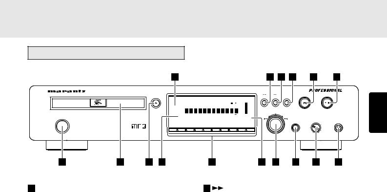
POWER ON/OFF switch |
(search forward) button |
This is used to turn the player’s power ON and OFF. When it is pressed, the display lights and the power is turned on; when it is pressed again, the power is turned off.
This is used to search forward during play.
It also serves as the album selector button when playing discs with MP3 files recorded on them.
 Disc tray
This is where the CD to be played is placed.
 OPEN/CLOSE
  button
This is used to open and close the disc tray. When it is pressed, the disc tray opens; when it is pressed again, it closes.
 Remote sensor
This senses the infrared control signals sent from the remote control unit.
 END WARNING indicator
This starts flashing 15 seconds before the end of the track now playing is reached.
 Numeric buttons (0 to 9)
These are used to specify the numbers of the tracks to be played.
 Display
This shows the settings, play status, text information, etc.

 (search backward) button
This is used to search backward during play.
It also serves as the album selector button when playing discs with MP3 files recorded on them.
 STOP
STOP  button
This is used to stop play.
 EASY JOG/push enter button
Preceding or subsequent tracks can be searched (tracks can be skipped) by turning the jog dial clockwise or counterclockwise. In addition, the play functions (play modes) can be set using the jog dial.
 QUICK REPLAY button
This is used to search backward from the current play position for the time equivalent to the setting and resume play.
The button is operated by the play setting function as the end monitor. In the case of the end monitor, play is resumed from the position which is before the end position of the track now playing by the duration which has been set.
 CUE
CUE  button
This button is used to move to and start set cue points.
 PLAY/PAUSE
  button
This is used to start play or temporarily suspend play.
 PHONES LEVEL control
This is used to adjust the headphones volume level. The level increases when it is turned clockwise.
 PHONES jack
The headphones are connected to this jack. Use headphones that come with a standard plug.
9
NAMES AND FUNCTIONS
Display
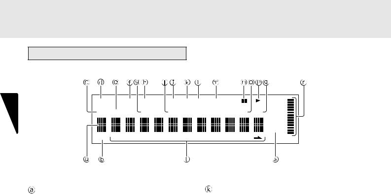
ENGLISH |
TIMER |
|
|
RNDM |
PROG |
|
|
A — B |
RPT |
1 |
S.PLAY |
|
|
|
|||
|
|
|
|
|
|
|
|
||||||||||
|
DISC |
TTL |
|
|
TRK |
|
|
INDX |
|
|
|
|
TTL |
TIME |
|||
|
|
|
|
|
|
|
|
|
|
|
|
|
|
|
|
|
MP3 |
|
TEXT |
1 |
2 |
3 |
4 |
5 |
6 |
7 |
8 |
9 |
10 |
11 12 |
13 14 |
15 16 |
17 18 |
19 20 |
|
Main display |
RPT (repeat) indicator |
This displays the time information and text information of the disc played, the setting menus, etc.
This lights during repeat play.
 TEXT indicator
This lights when a disc supporting CD-TEXT has been loaded.
 DISC indicator
This flashes during readout of the table of contents (TOC) information on the disc.
 TIMER indicator
This lights when timer play has been set.
 TTL (total track) indicator
This lights above the display of the total number of tracks recorded on the disc.
 RNDM (random) indicator
This lights during random play.
 TRK (track) indicator
This lights above the display of the number of the track being played, etc.
 PROG (program) indicator
This lights during program play.
 INDX (index) indicator
This lights above the display of the index number being played, etc.
 A-B (A-B repeat) indicator
This lights during A-B repeat play.
 1 (1-track repeat) indicator
This lights during 1-track repeat play.
 S.PLAY (single track play) indicator
This lights during single track play.

 (pause) indicator
This lights when play is temporarily suspended.
 TTL (total time) indicator
When the total remaining time or total program time is displayed, this lights above that display.

 (play) indicator
This lights during play.
 TIME indicator
This lights while the elapsed time or other such time is displayed.
 Pitch control indicator
This displays the pitch control setting.
 MP3 indicator
This lights when a disc on which MP3 files have been recorded is loaded.
 1 - 20,
  (music calendar)
This displays the track numbers recorded on the disc, the track numbers still to be played, and the track numbers programmed for program play. During MP3 file play, the album is displayed.
10
NAMES AND FUNCTIONS
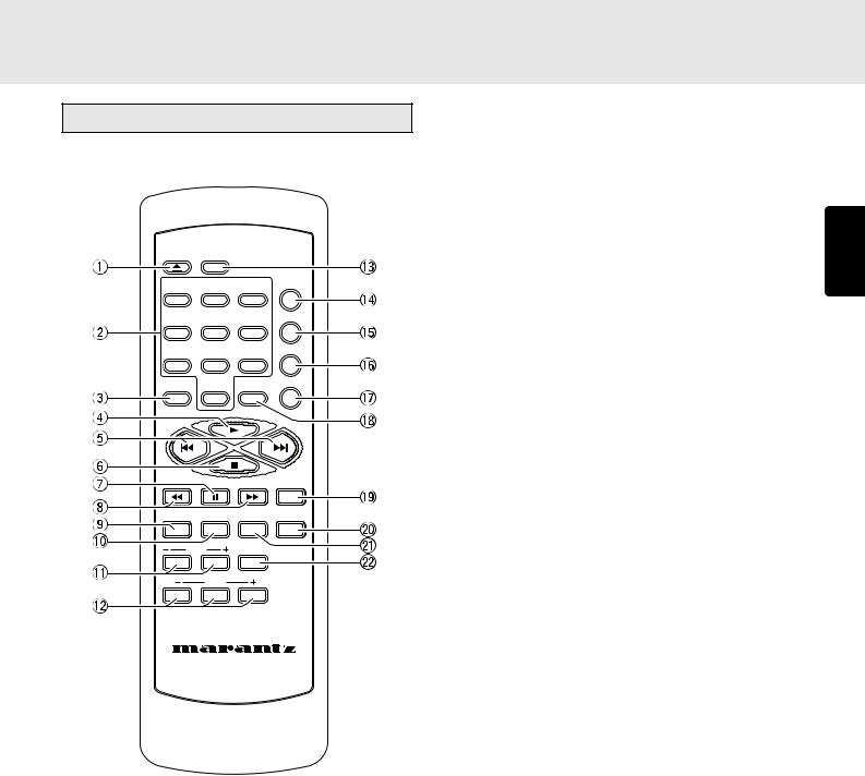
Remote control unit
OPEN/ |
|
|
|
CLOSE |
DISPLAY |
|
|
1 |
2 |
3 |
REPEAT |
|
|||
4 |
5 |
6 |
AMS |
|
|||
7 |
8 |
9 |
RANDOM |
|
|||
PROGRAM |
0 |
CANCEL |
A-B |
|
|||
|
|
|
TIME |
TEXT |
MENU |
ENTER |
SCROLL/ |
RECALL |
|||
INDEX |
Q. REPLAY |
|
|
|
PITCH |
|
|
|
RESET |
|
|
REMOTE CONTROLLER |
|||
|
RC7300CD |
|
|
 OPEN/CLOSE
  button
This is used to open and close the disc tray.
When it is pressed, the disc tray opens; when it is pressed again, it closes.
 Numeric buttons (0 to 9)
These are used to specify the numbers of the tracks to be played.
 PROGRAM button
This is pressed to initiate program play.

 (play) button
This is used to start play.

 ,
,  (track skip) buttons
 : Use this to return to the start of the track now playing or return to the start of the previous track.
 : Use this to advance to the start of the subsequent track.

 (stop) button
This is used to stop the play.

 (pause) button
This is used to temporarily suspend play.

 ,
,  (search) buttons
 : This button is used to search backward when it is held down during play.
 : This button is used to search forward when it is held down during play.
These buttons also serve as the album selector buttons when playing discs with MP3 files recorded on them.
 TEXT button
This is used to switch the main display from the time display to the text display.
 MENU button
This is used to switch to the play function (play mode) setting menu.
 INDEX -/+ (index down/up) buttons
These are used to skip and search indexes. They can be used with discs on which index numbers have been recorded.
 PITCH -/RESET/+ (pitch control down/reset/ up) buttons
These are used to adjust the play speed (pitch) with a
± 12% range.
 DISPLAY button
This button is used to select the brightness of the display window.
 REPEAT button
This is used to play one track or all the tracks on the disc repeatedly.
 AMS (auto music scan) button
This is used to play the intros of all the tracks in sequence starting from the first track for the duration equivalent to the setting.
 RANDOM button
This is used to play the tracks in a random sequence.
ENGLISH
11
ENGLISH
NAMES AND FUNCTIONS
 A-B (A-B repeat) button
This is used to set start point (A) and end point (B) when a particular section is to be played repeatedly.
 CANCEL button
This is used to cancel the programmed tracks.
 TIME button
This switches the main display from the text display to the time display. It can also switch the time display during play.
It can display how much time has elapsed and how much play time remains for the current track as well as how much time has elapsed and how much play time remains for the whole disc.
During MP3 file play, it displays the elapsed time only.
 SCROLL/RECALL button
This is used to scroll the text display when text is displayed. When it is pressed during program play, it is possible to check which tracks have been programmed.
 ENTER button
This is used to enter the play function settings.
 Q.REPLAY (quick replay) button
This is used to search backward from the current play position for the time equivalent to the setting and resume play.
Furthermore, operation is performed as the end monitor using one of the play setting functions. In the case of the end monitor, play is resumed from the position, which is a number of seconds that has been set, before the end position of the track now playing.
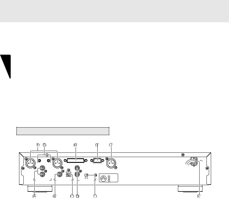
Rear panel
BALANCED |
|
|
|
|
|
|
R |
L |
|
|
|
|
|
OUTPUT LEVEL |
|
CONTROL I/O |
RS232C |
|
|
|
|
|
|
|
|
|
|
L |
|
|
IN |
|
|
|
|
|
|
|
|
DIGITAL OUT |
|
|
|
|
|
|
(SPDIF) |
|
R |
|
|
OUT |
|
CONNECTION |
|
|
|
|
|
|
1 |
GND |
|
|
|
EXTERNAL |
INTERNAL |
3 |
HOT (+) |
|
COAX. |
OPT. |
2 1 2 |
|||
ANALOG OUT |
DIGITAL OUT |
REMOTE CONTROL |
3 |
COLD (-) |
||
 ANALOG OUT (analog output) connectors
The music signals during play are output from these connectors.
 DIGITAL OUT COAX. (digital coaxial output) connector
The music signals during play are output digitally from this coaxial output connector.
*Digital signals are not output during MP3 file play or pitch control play.
 DIGITAL OUT OPT. (digital optical output) connector
The music signals during play are output digitally from this optical output connector.
*Digital signals are not output during MP3 file play or pitch control play.
 REMOTE CONTROL IN and OUT connectors
Using the remote control connecting cable, these connectors enable this player to be connected to a Marantz component equipped with remote control connectors. These connections make it possible to control an entire system that centers on the amplifier or other such component.
 EXTERNAL/INTERNAL switch
Before the player was shipped from the factory, this switch was set to INTERNAL to enable the remote sensor built into the player to be used.
Before using the connecting cable to make the connection between the player and the remote control connectors on a Marantz equipment, set the switch to EXTERNAL.
Note:
*Signals cannot be received from the remote control unit if the switch is kept at EXTERNAL when the player is to be used on its own.
12
 Loading...