


Slide Compound Saw
Equipped with Electric Blade Brake 305 mm (12”)
MODEL LS1212
DOUBLE
INSULATION
I N S T R U C T I O N M A N U A L
 WARNING:
For your personal safety, READ and UNDERSTAND before using. SAVE THESE INSTRUCTIONS FOR FUTURE REFERENCE.
w w w . m a k i t a t o o l s . c o m

SPECIFICATIONS
Blade diameter : ............................................................................................. |
305 mm (12”) |
Hole diameter : ................................................................................................ |
25.4 mm (1”) |
Max. Miter angle : ................................................................................... |
Left 47° , Right 60° |
Max. Bevel angle : ................................................................................... |
Left and Right 45° |
Max. Cutting capacities (H x W)
Miter angle |
|
|
Bevel angle |
|
|
|||
|
|
|
|
|
|
|
||
45° (left) |
0° |
|
45° (right) |
|||||
|
|
|||||||
|
|
|
|
|||||
|
* 69 mm x 230 mm |
* 120 mm x 230 mm |
* 49 mm x 230 mm |
|||||
|
(2-3/4” x 9”) |
(4-3/4” x 9”) |
(1-15/16” x 9”) |
|||||
0° |
61 mm x |
298 mm |
107 mm x |
298 mm |
40 mm x |
298 mm |
||
(2-3/8” x |
11-3/4”) |
(4-1/4” x |
11-3/4”) |
(1-9/16” x 11-3/4”) |
||||
|
||||||||
|
55 mm x |
310 mm |
98 mm x |
310 mm |
35 mm x |
310 mm |
||
|
(2-3/16” x 12-1/4”) |
(3-7/8” x |
12-1/4”) |
(1-3/8” x |
12-1/4”) |
|||
|
|
|
|
|||||
|
* 69 mm x 162mm |
* 120 mm x 162 mm |
* 49 mm x 162 mm |
|||||
|
(2-3/4” x 6-3/8”) |
(4-3/4” x |
6-3/8”) |
(1-15/16” x 6-3/8”) |
||||
45° (left and right) |
61 mm x |
211 mm |
107 mm x |
211 mm |
40 mm x |
211 mm |
||
(2-3/8” x 8-1/4”) |
(4-1/4” x |
8-1/4”) |
(1-9/16” x 8-1/4”) |
|||||
|
||||||||
|
55 mm x |
220 mm |
98 mm x |
220 mm |
35 mm x |
220 mm |
||
|
(2-3/16” x 8-5/8”) |
(3-7/8” x |
8-5/8”) |
(1-3/8” x 8-5/8”) |
||||
|
|
|
|
|
|
|||
|
|
|
* 120 mm x 115 mm |
|
|
|||
|
|
|
(4-3/4” x |
4-1/2”) |
|
|
||
60° (right) |
- |
|
107 mm x |
149 mm |
- |
|
||
|
(4-1/4” x |
5-7/8”) |
|
|||||
|
|
|
|
|
||||
|
|
|
98 mm x |
155 mm |
|
|
||
|
|
|
(9-7/8” x |
6-1/8”) |
|
|
||
|
|
|
|
|
|
|
|
|
(Note)
* mark indicates that a wood facing with the following thickness is used.
Miter angle |
|
Thickness of wood |
|
|
|
0° |
|
34 mm (1-5/16”) |
|
|
|
45° (left and light) |
|
24 mm (15/16”) |
|
|
|
60° (right) |
|
17 mm (11/16”) |
|
|
|
No load speed (RPM) : ........................................................................................ |
|
3,200/min. |
Dimensions (L x W x H) : ......... |
800 mm x 590 mm x 690 mm (31-1/2” x 23-1/4” x 27-1/4”) |
|
Net weight : ............................................................................................... |
|
22.0 kg (48.4 lbs) |
•Manufacturer reserves the right to change specifications without notice.
•Specifications may differ from country to country.
2

For Your Own Safety Read Instruction Manual
Before Operating Tool |
|
Save it for future reference |
|
GENERAL SAFETY PRECAUTIONS |
USA007-1 |
(For All Tools)
1.KNOW YOUR POWER TOOL. Read the owner’s manual carefully. Learn the tool’s applications and limitations, as well as the specific potential hazards peculiar to it.
2.KEEP GUARDS IN PLACE and in working order.
3.REMOVE ADJUSTING KEYS AND WRENCHES. Form habit of checking to see that keys and adjusting wrenches are removed from tool before turning it on.
4.KEEP WORK AREA CLEAN. Cluttered areas and benches invite accidents.
5.DON’T USE IN DANGEROUS ENVIRONMENT. Don’t use power tools in damp or wet locations, or expose them to rain. Keep work area well lighted. Don’t use tool in presence of flammable liquids or gases.
6.KEEP CHILDREN AWAY. All visitors should be kept safe distance from work area.
7.MAKE WORKSHOP KID PROOF with padlocks, master switches, or by removing starter keys.
8.DON’T FORCE TOOL. It will do the job better and safer at the rate for which it was designed.
9.USE RIGHT TOOL. Don’t force tool or attachment to do a job for which it was not designed.
10.WEAR PROPER APPAREL. Do not wear loose clothing, gloves, neckties, rings,
bracelets, or other jewelry which may get caught in moving parts. Nonslip footwear is recommended. Wear protective hair covering to contain long hair.
11.ALWAYS USE SAFETY GLASSES. Also use face or dust mask if cutting operation is dusty. Everyday eyeglasses only have impact resistant lenses, they are NOT safety glasses.
12.SECURE WORK. Use clamps or a vise to hold work when practical. It’s safer than using your hand and it frees both hands to operate tool.
13.DON’T OVERREACH. Keep proper footing and balance at all times.
14.MAINTAIN TOOLS WITH CARE. Keep tools sharp and clean for best and safest performance. Follow instructions for lubricating and changing accessories.
15.DISCONNECT TOOLS before servicing; when changing accessories such as blades, bits, cutters, and the like.
16.REDUCE THE RISK OF UNINTENTIONAL STARTING. Make sure switch is in off position before plugging in.
17.USE RECOMMENDED ACCESSORIES. Consult the owner’s manual for recommended accessories. The use of improper accessories may cause risk of injury to persons.
18.NEVER STAND ON TOOL. Serious injury could occur if the tool is tipped or if the cutting tool is unintentionally contacted.
3

19.CHECK DAMAGED PARTS. Before further use of the tool, a guard or other part that is damaged should be carefully checked to determine that it will operate properly and perform its intended function - check for alignment of moving parts, binding of moving parts, breakage of parts, mounting, and any other conditions that may affect its operation. A guard or other part that is damaged should be properly repaired or replaced.
20.DIRECTION OF FEED. Feed work into a blade or cutter against the direction of rotation of the blade or cutter only.
21.NEVER LEAVE TOOL RUNNING UNATTENDED. TURN POWER OFF. Don’t leave tool until it comes to a complete stop.
22.REPLACEMENT PARTS. When servicing use only identical replacement parts.
23.POLARIZED PLUGS. To reduce the risk of electric shock, this equipment has a polarized plug (one blade is wider than the other). This plug will fit in a polarized outlet only one way. If the plug does not fit fully in the outlet, reverse the plug. If it still does not fit, contact a qualified electrician to install the proper outlet. Do not change the plug in any way.
VOLTAGE WARNING: Before connecting the tool to a power source (receptacle, outlet, etc.) be sure the voltage supplied is the same as that specified on the nameplate of the tool. A power source with voltage greater than that specified for the tool can result in SERIOUS INJURY to the user - as well as damage to the tool. If in doubt, DO NOT PLUG IN THE TOOL. Using a power source with voltage less than the nameplate rating is harmful to the motor.
USE PROPER EXTENSION CORD. Make sure your extension cord is in good condition. When using an extension cord, be sure to use one heavy enough to carry the current your product will draw. An undersized cord will cause a drop in line voltage resulting in loss of power and overheating. Table 1 shows the correct size to use depending on cord length and nameplate ampere rating. If in doubt, use the next heavier gage. The smaller the gage number, the heavier the cord.
Table 1: Minimum gage for cord
Ampere Rating |
Volts |
|
Total length of cord in feet |
|
||||
120 V |
25 ft. |
|
50 ft. |
100 ft. |
|
150 ft. |
||
|
|
|
|
|||||
|
|
|
|
|
|
|
|
|
More Than |
Not More Than |
|
|
|
AWG |
|
|
|
|
|
|
|
|
|
|
|
|
0 |
6 |
|
18 |
|
16 |
16 |
|
14 |
|
|
|
|
|
|
|
|
|
6 |
10 |
|
18 |
|
16 |
14 |
|
12 |
|
|
|
|
|
|
|
|
|
10 |
12 |
|
16 |
|
16 |
14 |
|
12 |
|
|
|
|
|
|
|
|
|
12 |
16 |
|
14 |
|
12 |
Not Recommended |
||
|
|
|
|
|
|
|
|
|
4

ADDITIONAL SAFETY RULES |
USB036-2 |
DO NOT let comfort or familiarity with product (gained from repeated use) replace strict adherence to slide compound saw safety rules. If you use this tool unsafely or incorrectly, you can suffer serious personal injury.
1.Wear eye protection.
2.Keep hands out of path of saw blade. Avoid contact with any coasting blade. It can still cause severe injury.
3.Do not operate saw without guards in place. Check blade guard for proper closing before each use. Do not operate saw if blade guard does not move freely and close instantly. Never clamp or tie the blade guard into the open position.
4.Do not perform any operation freehand. The workpiece must be secured firmly against the turn base and guide fence with a vise during all operations. Never use your hand to secure the workpiece.
5.Never reach around saw blade.
6.Turn off tool and wait for saw blade to stop before moving workpiece or changing settings.
7.Unplug tool before changing blade or servicing.
8.To reduce the risk of injury, return carriage to the full rear position after each crosscut operation.
9.Always secure all moving portions before carrying the tool.
10.Stopper pin which locks the cutter head down is for carrying and storage purposes only and not for any cutting operations.
11.Do not use the tool in the presence of flammable liquids or gases.
12.Check the blade carefully for cracks or damage before operation. Replace cracked or damaged blade immediately. Gum and wood pitch hardened on blades slows saw and increases potential for kickback. Keep blade clean by first removing it from tool, then cleaning it with gum and pitch remover, hot water or kerosene. Never use gasoline to clean blade.
13.While making a slide cut, KICKBACK can occur. KICKBACK occurs when the blade binds in the workpiece during a cutting operation and the saw blade is driven back rapidly towards the operator. Loss of control and serious personal injury can result. If blade begins to bind during a cutting operation, do not continue to cut and release switch immediately.
14.Use only flanges specified for this tool.
15.Be careful not to damage the arbor, flanges (especially the installing surface) or bolt. Damage to these parts could result in blade breakage.
16.Make sure that the turn base is properly secured so it will not move during operation. Use the holes in the base to fasten the saw to a stable work platform or bench. NEVER use tool where operator positioning would be awkward.
17.For your safety, remove the chips, small pieces, etc. from the table top before operation.
18.Avoid cutting nails. Inspect for and remove all nails from the workpiece before operation.
5

19.Make sure the shaft lock is released before the switch is turned on.
20.Be sure that the blade does not contact the turn base in the lowest position.
21.Hold the handle firmly. Be aware that the saw moves up or down slightly during start-up and stopping.
22.Make sure the blade is not contacting the workpiece before the switch is turned on.
23.Before using the tool on an actual workpiece, let it run for a while. Watch for vibration or wobbling that could indicate poor installation or a poorly balanced blade.
24.Wait until the blade attains full speed before cutting.
25.Stop operation immediately if you notice anything abnormal.
26.Do not attempt to lock the trigger in the on position.
27.Be alert at all times, especially during repetitive, monotonous operations. Do not be lulled into a false sense of security. Blades are extremely unforgiving.
28.Always use accessories recommended in this manual. Use of improper accessories
such as abrasive wheels may cause an injury.
29.NEVER hold workpiece on right side of blade with left hand or vice versa. This is called cross-armed cutting and exposes user to risk of SERIOUS PERSONAL INJURY as shown in the figure. ALWAYS use vise to secure workpiece.
30.Do not abuse cord. Never yank cord to disconnect it from the receptacle. Keep cord away from heat, oil, water and sharp objects.
31.NEVER stack workpieces on the table top to speed cutting operations. Cut only one piece at a time.
32.Some material contains chemicals which may be toxic. Take caution to prevent dust inhalation and skin contact. Follow material supplier safety data.
SAVE THESE INSTRUCTIONS
 WARNING:
MISUSE or failure to follow the safety rules stated in this instruction manual may cause serious personal injury.
6
INSTALLATION
001564 |
Bench mounting |
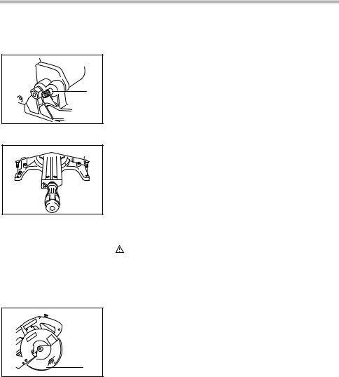
When the tool is shipped, the handle is locked in the lowered position by the stopper pin. Release the stopper pin by lower-
ing the handle slightly and pulling the stopper pin.
1
1. Stopper pin
002224 This tool should be bolted with four bolts to a level and stable
1 |
surface using the bolt holes provided in the tool’s base. This |
|
|
|
will help prevent tipping and possible injury. |
1. Bolt
FUNCTIONAL DESCRIPTION
CAUTION:
•Always be sure that the tool is switched off and unplugged before adjusting or checking function on the tool.
001535
1
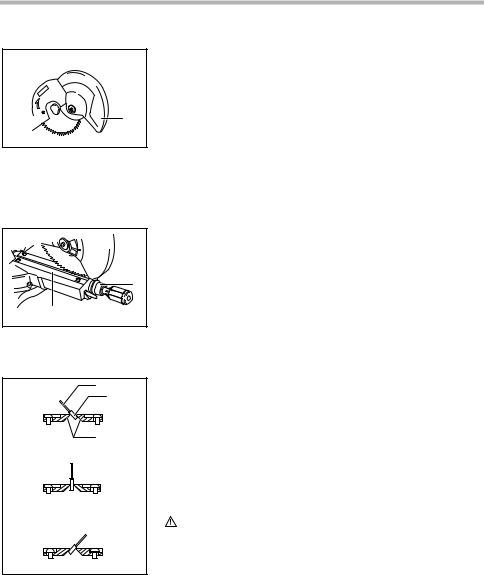
1. Blade guard
Blade guard
When lowering the handle, the blade guard rises automatically. The guard is spring loaded so it returns to its original position when the cut is completed and the handle is raised. NEVER DEFEAT OR REMOVE THE BLADE GUARD OR THE SPRING WHICH ATTACHES TO THE GUARD.
In the interest of your personal safety, always maintain the blade guard in good condition. Any irregular operation of the blade guard should be corrected immediately. Check to assure spring loaded return action of guard. NEVER USE THE TOOL IF THE BLADE GUARD OR SPRING ARE DAMAGED, FAULTY OR REMOVED. DOING SO IS HIGHLY DANGEROUS AND CAN CAUSE SERIOUS PERSONAL INJURY.
If the see-through blade guard becomes dirty, or sawdust adheres to it in such a way that the blade is no longer easily visible, unplug the saw and clean the guard carefully with a damp cloth. Do not use solvents or any petroleum-based
cleaners on the plastic guard. |
7 |
001782
1
1. Blade guard
If the blade guard is especially dirty and vision through the guard is impaired, use the supplied socket wrench to loosen the hex bolt holding the center cover. Loosen the hex bolt by turning it counterclockwise and raise the blade guard and center cover. With the blade guard so positioned, cleaning can be more completely and efficiently accomplished. When cleaning is complete, reverse procedure above and secure bolt. Do not remove spring holding blade guard. If guard becomes discolored through age or UV light exposure, contact a Makita service center for a new guard. DO NOT DEFEAT OR REMOVE GUARD.
002225 |
Positioning kerf board |
|
|
This tool is provided with the kerf boards in the turn base to |
|
|
minimize tearing on the exit side of a cut. The kerf boards are |
|
2 |
factory adjusted so that the saw blade does not contact the |
|
kerf boards. Before use, adjust the kerf boards as follows: |
||
1 |
First, unplug the tool. Loosen all the screws (2 each on left |
|
and right) securing the kerf boards. Re-tighten them only to |
||
|
||
1. Kerf board |
the extent that the kerf boards can still be easily moved by |
|
2. Knob |
hand. Lower the handle fully and push in the stopper pin to |
|
001538 |
lock the handle in the lowered position. Loosen the knob |
|
which secures the slide poles. Pull the carriage toward you |
||
1 |
||
fully. Adjust the kerf boards so that the kerf boards just con- |
||
2 |
||
|
tact the sides of the blade teeth. Tighten the front screws (do |
|
|
not tighten firmly). Push the carriage toward the guide fence |
|
3 |
fully and adjust the kerf boards so that the kerf boards just |
|
4 |
contact the sides of blade teeth. Tighten the rear screws (do |
|
|
||
|
not tighten firmly). |
|
|
After adjusting the kerf boards, release the stopper pin and |
|
5 |
raise the handle. Then tighten all the screws securely. |
|
|
CAUTION:
•Before and after changing the bevel angle, always adjust
the kerf boards as described above.
6
1.Saw blade
2.Blade teeth
3.Kerf board
4.Left bevel cut
5.Straight cut
6.Right bevel cut
8
002226
1
2
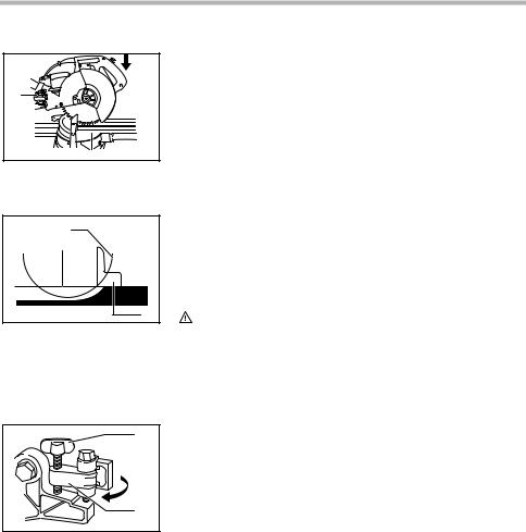
1.Adjusting bolt
2.Turn Base
001540 |
2 |
1 |
3 |
1.Top surface ot turn base
2.Periphery of blade
3.Guide fence
Maintaining maximum cutting capacity
This tool is factory adjusted to provide the maximum cutting capacity for a 305 mm (12”) saw blade.
When installing a new blade, always check the lower limit position of the blade and if necessary, adjust it as follows:
First, unplug the tool. Push the carriage toward the guide fence fully and lower the handle completely. Use the socket wrench to turn the adjusting bolt until the periphery of the blade extends slightly below the top surface of the turn base at the point where the front face of the guide fence meets the top surface of the turn base.
With the tool unplugged, rotate the blade by hand while holding the handle all the way down to be sure that the blade does not contact any part of the lower base. Re-adjust slightly, if necessary.
CAUTION:
•After installing a new blade, always be sure that the blade does not contact any part of the lower base when the handle is lowered completely. Always do this with the tool unplugged.
001562 |
Stopper arm |
1 |
The lower limit position of the blade can be easily adjusted |
|
|
|
with the stopper arm. To adjust it, move the stopper arm in |
|
the direction of the arrow as shown in the figure. Adjust the |
|
adjusting screw so that the blade stops at the desired posi- |
2 |
tion when lowering the handle fully. |
|
1.Adjusting screw
2.Stopper arm
9
|
|
002227 |
|
|
5 |
1 |
2 |
4 |
|
|
3 |
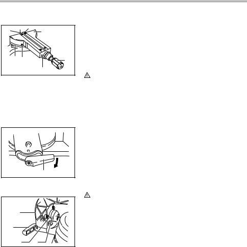
1.Miter scale
2.Pointer
3.Lock lever
4.Grip
5.Turn base
001542
1
1. Lever
001543
1
2
3 4
1.Arm
2.Lever
3.Pointer
4.Bevel scale
Adjusting the miter angle
Loosen the grip by turning counterclockwise. Turn the turn base while pressing down the lock lever. When you have moved the grip to the position where the pointer points to the desired angle on the miter scale, securely tighten the grip clockwise.
CAUTION:
•When turning the turn base, be sure to raise the handle fully.
•After changing the miter angle, always secure the turn base by tightening the grip firmly.
Adjusting the bevel angle
To adjust the bevel angle, loosen the lever at the rear of the tool counterclockwise. Unlock the arm by pushing the handle somewhat strongly in the direction that you intend to tilt the saw blade.
Tilt the saw blade until the pointer points to the desired angle on the bevel scale. Then tighten the lever clockwise firmly to secure the arm.
CAUTION:
•When tilting the saw blade, be sure to raise the handle fully.
•After changing the bevel angle, always secure the arm by tightening the lever clockwise.
•When changing bevel angles, be sure to position the kerf boards appropriately as explained in the “Positioning kerf boards” section.
10
001551
 1 2
1 2
3
1.Lock-off button
2.Handle
3.Switch trigger
Switch action
CAUTION:
•Before plugging in the tool, always check to see that the switch trigger actuates properly and returns to the “OFF” position when released.
•When not using the tool, remove the lock-off button and store it in a secure place. This prevents unauthorized operation.
•Do not pull the switch trigger hard without pressing in the lock-off button. This can cause switch breakage.
To prevent the switch trigger from being accidentally pulled, a lock-off button is provided. To start the tool, press in the lockoff button and pull the switch trigger. Release the switch trigger to stop.
WARNING:
•NEVER use tool without a fully operative switch trigger. Any tool with an inoperative switch is HIGHLY DANGEROUS and must be repaired before further usage.
•For your safety, this tool is equipped with a lock-off button which prevents the tool from unintended starting. NEVER use the tool if it runs when you simply pull the switch trigger without pressing the lock-off button. Return tool to a Makita service center for proper repairs BEFORE further usage.
•NEVER tape down or defeat purpose and function of lock-off button.
Electric brake
This tool is equipped with an electric blade brake. If the tool consistently fails to quickly stop blade after switch trigger release, have tool serviced at a Makita service center.
The blade brake system is not a substitute for blade guard. NEVER USE TOOL WITHOUT A FUNCTIONING BLADE GUARD. SERIOUS PERSONAL INJURY CAN RESULT.
11
 Loading...