


Owner`s Manual
26MF605W/32MF605W Series LCD TV
NEED HELP?CALL US!
MAGNAVOX REPRESENTATIVES ARE READY TO HELP YOU WITH ANY QUESTIONS ABOUT YOUR NEW PRODUCT. WE CAN GUIDE YOU THROUGH CONNECTIONS, FIRST-TIME SETUP, AND ANY OF THE FEATURES. WE WANT YOU TO START ENJOYING YOUR NEW PRODUCT RIGHT AWAY.
CALL US BEFORE YOU CONSIDER RETURNING THE PRODUCT. 1-800-705-2000
OR VISIT US ON THE WEB AT WWW.USASUPPORT.MAGNAVOX.COM
Important!
Return your Warranty Registration Card within 10 days.
3138 155 23445
RETURN YOUR PRODUCT REGISTRATION CARD TODAY
TO GET THE VERY MOST FROM YOUR PURCHASE.
Registering your model with MAGNAVOX makes you eligible for all of the valuable benefits listed below, so don’t miss out. Complete and return your Product Registration Card at once to ensure:
*Proof of |
|
|
*Product Safety |
|
*Additional |
|||||
|
|
|||||||||
Purchase |
|
|
Notification |
|
|
|
Benefits of Product |
|||
Returning the enclosed card |
|
|
By registering your product, you’ll |
|
Ownership |
|||||
guarantees that your date of |
|
|
receive notification - directly from |
|
||||||
purchase will be on file, so no |
|
|
the manufacturer - in the rare case |
|
Registering your product guaran- |
|||||
|
|
|
tees that you’ll receive all of the |
|||||||
additional paperwork will be |
|
|
of a product recall or safety defect. |
|
||||||
|
|
|
privileges to which you’re entitled, |
|||||||
required from you to obtain |
|
|
|
|
|
|
|
|||
|
|
|
|
|
|
|
including special money-saving |
|||
warranty service. |
|
|
|
|
|
|
|
|||
|
|
|
|
|
|
|
offers. |
|||
|
|
|
|
|
|
|
|
|||
|
|
|
|
|
|
|
|
|
|
|
|
|
|
|
|
Know these safety symbols |
|||||
Congratulations on your purchase, |
|
|||||||||
|
|
|
|
|
|
|
||||
and welcome to the“family!” |
|
|
|
|
|
|
|
|
||
Dear MAGNAVOX product owner: |
|
|
|
|
|
|
|
|||
|
|
|
|
|
|
|
||||
Thank you for your confidence in |
|
|
|
This “bolt of lightning” indicates |
||||||
MAGNAVOX.You’ve selected one of the |
|
|
uninsulated material within your unit may |
|||||||
best-built,best-backed products available today. |
|
cause an electrical shock. For the safety of |
||||||||
We’ll do everything in our power to keep you |
|
everyone in your household, please do not |
||||||||
|
remove product covering. |
|||||||||
happy with your purchase for many years to |
|
|||||||||
|
|
|
|
|
|
|
||||
come. |
|
|
|
The “exclamation point” calls attention to |
||||||
As a member of the MAGNAVOX“family,” |
|
|
||||||||
|
|
features for which you should read the |
||||||||
you’re entitled to protection by one of the |
|
enclosed literature closely to prevent |
||||||||
most comprehensive warranties and |
|
operating and maintenance problems. |
||||||||
outstanding service networks in the industry. |
|
WARNING: To reduce the risk of fire or |
||||||||
What’s more,your purchase guarantees you’ll |
|
electric shock, this apparatus should not be |
||||||||
receive all the information and special offers for |
|
exposed to rain or moisture and objects filled with |
||||||||
which you qualify,plus easy access to |
|
liquids, such as vases, should not be placed on this |
||||||||
accessories from our convenient home |
|
apparatus. |
|
|
|
|
||||
shopping network. |
|
|
CAUTION: To prevent electric shock, match |
|||||||
Most importantly,you can count on our |
|
wide blade of plug to wide slot, fully insert. |
||||||||
uncompromising commitment to your total |
|
ATTENTION: Pour éviter les choc |
||||||||
satisfaction. |
|
|
électriques, introduire la lame la plus large de la fiche |
|||||||
All of this is our way of saying welcome - and |
|
dans la borne correspondante de la prise et pousser |
||||||||
thanks for investing in a MAGNAVOX product. |
|
jusqu’au fond. |
|
|
|
|
||||
|
|
|
|
|
|
|||||
P.S.To getthemostfromyourMAGNAVOX |
|
For Customer Use |
||||||||
purchase,you must return yourWarranty |
|
Enter below the Serial No. which is located |
||||||||
Registration Card within 10 days.So |
|
on the rear of the cabinet. Retain this |
||||||||
please mail it to us right now! |
|
|
information for future reference. |
|||||||
|
|
Model No._______________________ |
||||||||
|
|
|
|
|
||||||
|
|
|
|
|
Serial No. _______________________ |
|||||
|
|
|
|
|
||||||
|
|
|
|
|
||||||
Visit our World Wide Web Site at http://www.usasupport.magnavox.com |
||||||||||
2
IMPORTANT SAFETY INSTRUCTIONS
READ BEFORE OPERATING EQUIPMENT
1.Read these instructions.
2.Keep these instructions.
3.Heed all warnings.
4.Follow all instructions.
5.Do not use this apparatus near water.
6.Clean only with a dry cloth.
7.Do not block any of the ventilation openings.
Install in accordance with the manufacturers instructions.
8.Do not install near any heat sources such as radiators, heat registers, stoves, or other apparatus (including amplifiers) that produce heat.
9.Do not defeat the safety purpose of the polarized or grounding-type plug. A polarized plug has two blades with one wider than the other. A grounding type plug has two blades and third grounding prong. The wide blade or third prong are provided for your safety. When the provided plug does not fit into your outlet, consult an electrician for replacement of the obsolete outlet.
10.Protect the power cord from being walked on or pinched particularly at plugs, convenience receptacles, and the point where they exit from the apparatus.
11.Only use attachments/accessories specified by the manufacturer.
12.Use only with a cart, stand, tripod, bracket, or table

 specified by the manufacturer, or sold with the
  apparatus. When a cart is used, use caution when
moving the cart/apparatus combination to avoid injury from tip-over.
13.Unplug this apparatus during lightning storms or when unused for long periods of time.
14.Refer all servicing to qualified service personnel. Servicing is required when the apparatus has been damaged in any way, such as power-supply cord or plug is damaged, liquid has been spilled or objects have fallen into apparatus, the apparatus has been exposed to rain or moisture, does not operate normally, or has been dropped.
15.This product may contain lead and mercury. Disposal of these materials may be regulated due to environmental considerations. For disposal or recycling information, please contact your local authorities or the Electronic Industries Alliance: www.eiae.org
16.Damage Requiring Service - The appliance should be serviced by qualified service personnel when:
A.The power supply cord or the plug has been damaged;
B.Objects have fallen, or liquid has been spilled into the appliance;
C.The appliance has been exposed to rain
D.The appliance does not appear to operate normally or exhibits a marked change in performance;
E.The appliance has been dropped, or the enclosure damaged.
17.Tilt/Stability - All televisions must comply with recommended international global safety standards for tilt and stability properties of its cabinet design.
• Do not compromise these design standards by applying excessive pull force to the front, or top, of the cabinet which could ultimately overturn the product.
• Also, do not endanger yourself, or children, by placing electronic equipment/toys on the top of the cabinet. Such items could unsuspectingly fall from the top of the set and cause product damage and/or personal injury.
18.Wall or Ceiling Mounting - The appliance should be mounted to a wall or ceiling only as recommended by the manufacturer.
19.Power Lines - An outdoor antenna should be located away from power lines.
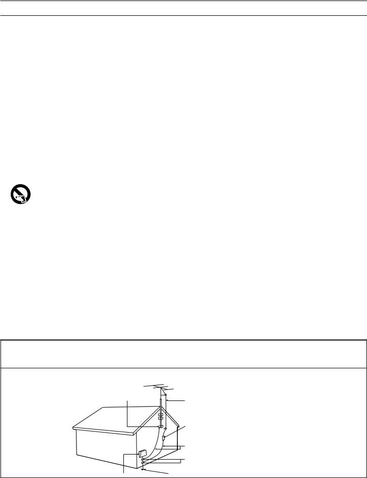
20.Outdoor Antenna Grounding - If an outside antenna is connected to the receiver, be sure the antenna system is grounded so as to provide some protection against voltage surges and built up static charges.
Section 810 of the National Electric Code, ANSI/NFPA No. 70-1984, provides information with respect to proper grounding of the mast and supporting structure, grounding of the lead-in wire to an antenna discharge unit, size of grounding connectors, location of antenna-discharge unit, connection to grounding electrodes, and requirements for the grounding electrode. See Figure below.
21.Object and Liquid Entry - Care should be taken so that objects do not fall and liquids are not spilled into the enclosure through openings.
22.Battery Usage CAUTION - To prevent battery leakage that may result in bodily injury, property damage, or damage to the unit:
• Install all batteries correctly, with + and - aligned as marked on the unit.
• Do not mix batteries (old and new or carbon and alkaline, etc.).
• Remove batteries when the unit is not used for a long time.
Note to the CATV system installer: This reminder is provided to call the CATV system installer’s attention to Article 82040 of the NEC that provides guidelines for proper grounding and, in particular, specifies that the cable ground shall be connected to the grounding system of the building, as close to the point of cable entry as practical.
ExampleofAntennaGroundingasperNEC-NationalElectricCode
GROUND CLAMP |
ANTENNA LEAD IN WIRE |
|
ANTENNA DISCHARGE UNIT (NEC SECTION 810-20)
GROUNDING CONDUCTORS (NEC SECTION 810-21)
GROUND CLAMPS
ELECTRIC SERVICE EQUIPMENT |
POWER SERVICE GROUNDING ELECTRODE SYSTEM (NEC ART 250, PART H) |
|
3
Introduction |
|
Welcome/Registration of Your TV............................................. |
2 |
IMPORTANT SAFETY INSTRUCTIONS................................ |
3 |
Table of Content.............................................................................. |
4 |
Getting Started |
|
Before Installation............................................................. |
5 |
Installing LCD TV on The Wall.................................................... |
6 |
Basic TV and Remote Control Operations............................. |
7 |
Remote Control............................................................................... |
8 |
Antenna Connection....................................................................... |
9 |
Connecting the Power cord......................................................... |
9 |
Basic Cable TV Connection......................................................... |
9 |
Cable Box Connections................................................................. |
10 |
VCR, DVD Player, or other Devices |
|
with RCA Connectors.................................................................... |
11 |
DVD Player or other Video Devices |
|
with Component Video Connectors......................................... |
12 |
Digital TV Receiver, or a Digital Satellite Receiver |
|
with HD (High Definition) Output............................................. |
13 |
Digital Satellite Receiver with DVI connector.......................... |
14 |
PC (Monitor) Connection.............................................................. |
15 |
AV Output.......................................................................................... |
16 |
Install Menu |
|
Language Settings.............................................................. |
17 |
Tuner Mode Control....................................................................... |
18 |
Auto Program (Setting Up Channels)........................................ |
19 |
Channel Edit Control...................................................................... |
20 |
Factory Reset.................................................................................... |
21 |
Smart Picture and Smart Sound |
|
Smart Picture Control................................................... |
22 |
Smart Sound Control.................................................................... |
22 |
Picture Menu |
|
TV Picture Menu Controls........................................... |
23 |
Sound Menu |
|
TV Sound Menu Controls............................................ |
24 |
Features Menu |
|
Auto Lock......................................................................... |
25 |
Auto Lock Access Code................................................................ |
26 |
Auto Lock Program......................................................................... |
27 |
Auto Lock - Movie Ratings............................................................ |
28 |
Auto Lock - TV Ratings................................................................. |
29 |
Using The Picture Format............................................................. |
30 |
Closed Captions............................................................................. |
31 |
PC Mode |
|
PC Picture Controls...................................................... |
32 |
PC Audio Controls........................................................................ |
33 |
Using PC PIP (Picture In Picture) Feature............................... |
34 |
Setting Up The PC Mode............................................................. |
35 |
(Personal Computer Monitor)..................................................... |
35 |
CONTENT |
|
General Information |
|
Trouble Shooting Tips................................................... |
36 |
Care And Cleaning......................................................................... |
37 |
Index.................................................................................................. |
38 |
Regulatory......................................................................................... |
39 |
Regulatory......................................................................................... |
40 |
Factory Service Locations............................................................ |
41 |
Limited Warranty........................................................................... |
42 |
Here are a few of the special features of your new LCD TV. Audio/Video In Jacks: Use to quickly connect other equipment to your LCD TV.
Automatic Channel Programming (Auto Program): Quick and easy setup of available channels.
Closed Captioning: Allows the viewer to read TV program dialog or voice conversations as on-screen text. On-screen Menus: Helpful messages (in English, Spanish or French) for setting TV controls.
Remote Control: Works your LCD TV features.
Sleep Timer: Turns off the LCD TV within an amount of time you specify (15-240 minutes from the current time). AutoLock: Lets you block viewing of certain TV channels if you do not want your children viewing inappropriate material.
Standard broadcast (VHF/UHF) or Cable TV channel capability
Stereo capability: Includes a built-in amplifier and twin-speaker system, allowing reception of TV programs broadcast in stereo. Treble, Bass, and Balance: Enhance the LCD TV’s sound.
NOTE:This manual covers different versions and models.Not all features described in this manual will match those of your LCDTV. This is normal and does not require you contacting your dealer or requesting service.
END-OF-LIFE DISPOSAL
Your new LCD TV and its packaging contain materials that can be recycled and reused. Specialized companies can recycle your product to increase the amount of reusable materials and minimize the amounts that need to be properly disposed.
Your product also uses batteries that should not be thrown away when depleted, but should be handed in and disposed of as small chemical waste.
When you replace your existing equipment, please find out about the local regulations regarding disposal of your old television, batteries, and packing materials.
4
BEFORE INSTALLATION
Positioning the LCD TV.
.Place the LCDTV on a solid,stable surface.Be sure the surface is strong enough to handle the weight of the LCDTV.
.Try to leave at least 6”of space around each side of the LCD TV cabinet to allow for proper ventilation.
.Do not place the LCDTV near a radiator or other source of heat.
.Do not place the LCDTV where it can be exposed to rain or excessive moisture.
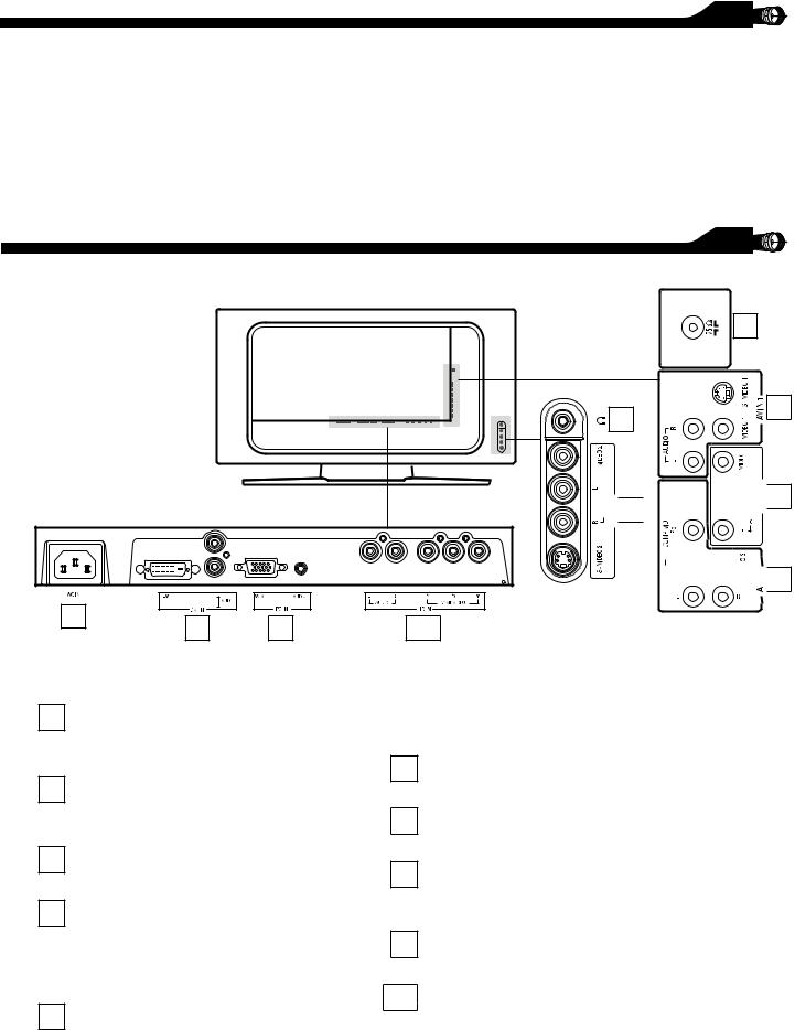
IDENTIFYING ALL CONNECTORS (BACKSIDE)
|
6 |
3 |
1 |
|


 2
2


 5
5


 4
4
7 |
8 |
9 |
10 |
|
1 AV IN 1
Connects to the output jacks of your VCR or other video equipment.
2 AV IN 2
Connects to the output jacks of your VCR or other video equipment.
3 Headphones jack
Connect to your headphones.
4 AV IN 3
Y, Pb, Pr Input jacks
Connects to the component video connectors of your DVD player or other video equipments with SD (Standard Defi nition) video format.
5 AV OUT
Connects to the input jacks of your video and audio equipment.
6
7
8
9
10
Video output through AV OUT jacks is available only when your LCD TV is displaying CVBS or RF signals.
VHF/UHF
Connect to your VHF/UHF antenna or cable
AC IN
Connects the supplied AC power cord.
DVI IN (HDCP)
Connect to your DVD player or other video equipment with DVI/HDCP output connectors.
PC IN
Connect to your PC with VGA type video output.
HD (High Definition) IN
Connect to the Digital Satellite Receiver or other video equipments that supports YPbPr HD (High Defi nition) video format.
5

INSTALLING LCDTV ONTHEWALL
Before you can install your LCD TV on the wall, you must fi rst remove the base using the steps below:
1Place the set facing down on a fl at surface with a protective sheet or cloth beneath the TV.
3 Remove the 2 metal pins.
2Remove 3 screws from the base. Grasp the base and pull it out.
2 1
3
4Attach the supplied base cover. Your LCD TV is now ready for wall mounting.
When installing the LCDTV on the wall,please consult a professional technician for proper installing. The manufacture accepts no liability for installations not performed by professional technician.
100x100mm |
200x100mm |
|
26"
32"
6
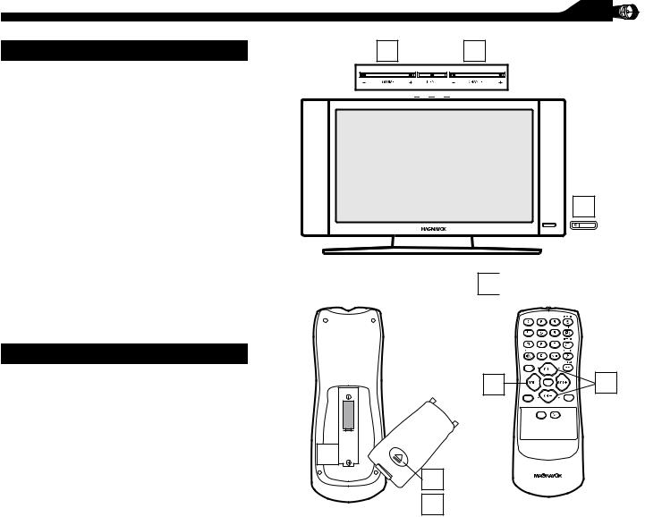
BASICTV AND REMOTE CONTROL OPERATIONS
TELEVISIONAND REMOTE CONTROL |
2 |
3 |
1 Press POWER to turn on the LCD TV. |
|
|
2Press VOLUME + to increase the sound level. Or, press VOLUME– to lower the sound level.
3 |
Press CH+ or CHto select channels. |
|
1 |
|
Point the remote control toward on the |
4 front of the LCD TV when operating the |
|
|
LCD TV with the remote. |
5
6
7
BATTERY INSTALLATION
Remove the battery compartment lid on the back of the remote.
Place two AAA batteries in the remote. Be sure the (+) and (-) ends of the batteries line up as marked inside the battery compartment.
Reattach the battery compartment lid.
4

MENU
2 |
|
OK |
SOURCE |
PIP |
|
|
|
CC |
6 
5
7
3
7
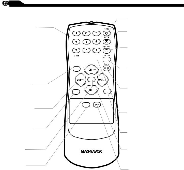
REMOTE CONTROL
Number buttons
Press to select TV channels. When selecting single-digit channels, press the number of the desired channel. The LCD TV will pause for a few seconds then tune to the selected channel.
Mute button


Press to eliminate or restore the
LCD TV sound. Mute will appear MENU on the screen when the sound is
muted.
Menu button |
|
OK |
|
|
|
Press to activate onscreen menu, |
|
PIP |
back to previous level inside the |
SOURCE |
|
onscreen menu, also press to exit |
|
|
the onscreen menu. |
|
|
Volume button |
|
CC |
|
|
Press to increase or decrease the sound level, also press to navigate left/right in onscreen menu.
Source button
Press to select the video input source: PC, DV1, AV1, AV2, AV3, S-V1, S-V2, Component, HD
OK button
Press to confirm the option you selected in the onscreen menu.
C.C button
Press the C.C button to select CC on or CC off.
Standby (Power) button
Press to turn the LCD TV on or off.
Sleep button
Press to set the LCD TV to turn itself off within a certain time.
Smart Picture button
Press repeatedly to select either Personal, Movie, Sports, Weak signal, Multimedia or Night picture setting.
Smart Sound button
Press repeatedly to select among the 4 settings; Personal, News, Music, or Theater.
Picture Format button
Press the FORMAT button repeatedly to toggle among the four screen format sizes; 4:3, SUPERWIDE, ZOOM 16:9 or WIDESCREEN.
Previous Channel button
Press to go to previously selected channel.
PIP button
Press repeatedly to change the size of PIP window in PC mode.
Channel button
Press to adjust the channel up or down. Also press to select or navigate up/down in onscreen menu.
SAP button
Press to select a sound mode if available with the TV programming: Mono, Stereo, or SAP.
8
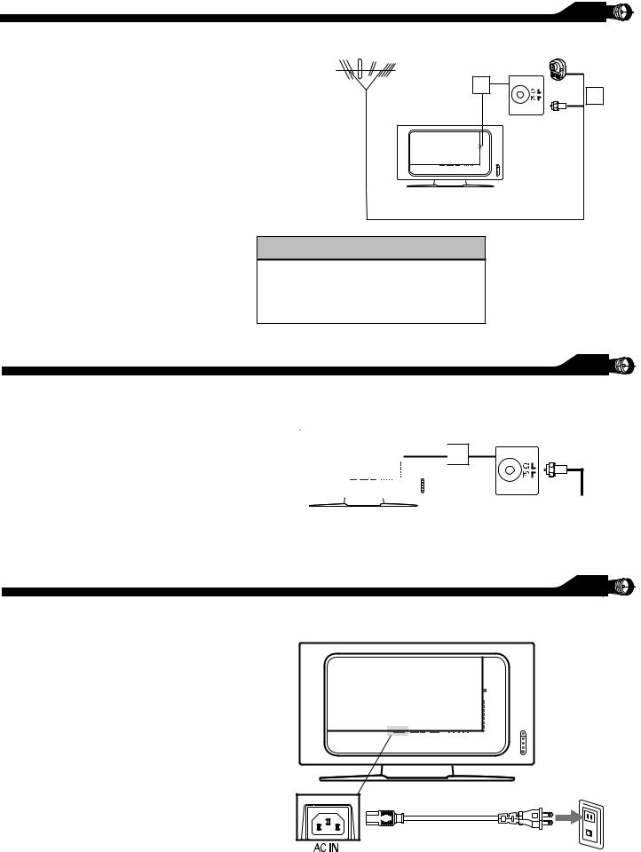
Acombination antenna receives normal broadcast channels (VHF 2–13 and UHF
14–69). Your connection is easy because there is only one 75 Ω antenna jack on the back of your TV, and that’s where the antenna goes.
1If your antenna has a round cable
(75 Ω) on the end, then you’re ready to connect it to the LCD TV. If your antenna has fl at, twin-lead wire (300Ω), you fi rst need to attach the antenna wires to the screws on a 300-75Ω adapter(not supplied).
2Connect the antenna (or adapter) to the TV jack (marked 75 Ω) on the rear of the LCD TV. If the end of the antenna wire is threaded, screw it down fi nger tight.
ANTENNA CONNECTION
Outdoor or Indoor Antenna (Combination VHF/UHF)
2
HELPFUL HINT
Select weak signal mode via the smart picture settings in case your antenna connection is showing a lot of noise or strange patterns.
BASIC CABLETV CONNECTION
Your Cable TV signal into your home may be a single, 75 Ω cable. If so, this connection is very simple. Follow the step below to connect your Cable TV signal to
your new LCD TV.
1Connect the cable TV signal to the TV jack (marked 75 Ω) on the rear of the LCD TV. Screw it down fi nger tight.
 1
1
Rear Jack panel of Television
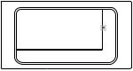
CONNECTING THE POWER CORD
Complete other connections prior to connecting the power cord.
1Connect the power cord to the AC IN connector of the LCD TV.
2Connect the other plug of the power cord to a wall outlet.
Twin-lead wire
to 300-75Ω adpter
or 1
Antenna with 75Ω cable
The Cable TV singal from Cable Company 75Ω coaxial cable
Wall outlet
9

CABLE BOX CONNECTIONS
If you have a Cable Box, follow either set of these steps to complete your connections.
Disconnect all power sources before making any connections.
Cable Box with RF In/Out Jacks
This connection will not supply Stereo sound to the LCD TV.
1Connect the Cable TV signal to the IN jack (or RF IN or CABLE IN) on the Cable Box.
2Connect an RF coaxial cable (not supplied) to the OUT jack (or TO TV or RF OUT) of the Cable Box.
3Connect the other end of the coaxial cable to the TV jack (marked 75 Ω) on the rear of the LCD TV.
4Set the Channel (or Output channel) switch of the Cable Box to 3 or 4. Set the TV to the same channel. When watching TV programming, change channels at the Cable Box, not the LCD TV.
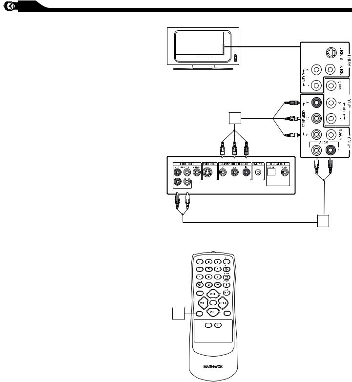
Cable Box with AV (Audio/Video) Out Jacks
This connection will supply Stereo sound to the LCD TV.
1Connect the Cable TV signal to the IN jack (or RF IN or CABLE IN) on the Cable Box.
2Using an RCA-type Video and Audio cable (marked with yellow, red, and white), connect the Cable Box’s Video and Audio Out jacks to the TV’s Video and Audio In jacks.
Note:
1.If your Cable Box is equipped with a S-Video Out Jack, use the S-Video connection for a better picture detail and clarity. Use the S-Video cable to connect the Cable Box’s S-Video Out jacks to the TV’s S-Video In jacks.
2.You can also use the Video and Audio jacks in AV IN 2 and AV IN 3 located on the rear of the TV to connect your Cable Box.
3.Use the SOURCE button on the remote control to select AV 1 (or AV2, AV3, S-Video1, or S-Video2 if you use the different jacks for this hookup) to watch Cable TV (your Cable Box must be turned on).
3
|
2 |
|
|
75Ω coaxial cable |
|
OUTPUT |
4 |
||
|
3 |
CH |
4 |
|
CABLE |
TO |
|
|
|
IN |
TV |
|
|
|
Cable Box
1
The Cable TV singal from Cable Company
2
OUTPUT
CH
|
3 |
4 |
|
|
|
|
CABLE |
TO |
L |
AUDIO |
R |
VIDEO |
|
|
|
OUT |
S VIDEO |
|||
IN |
TV |
|
OUT |
|
||
|
|
|
|
Cable Box
Cable TV singal
1
10
VCR,DVD PLAYER,OR OTHER DEVICES
WITH RCA CONNECTORS
The AV IN jacks on the rear of the LCD TV enable quick connections of other equipment. Connect a DVD player,VCRVideo
Game, Camcorder, etc., to these jacks.To view the material playing on the other equipment, set the LCDTV to its AV mode.
Disconnect all power sources before making any connections.
1Using an RCA-type Video and Audio cable (usually marked yellow, red, and white), connect the VCR’s Video and Audio Out jacks to the TV’s Video and Audio In jacks.
2Use SOURCE button on the remote control to select AV 1 (or AV2, AV3, S-Video1, or S-Video2 if you use the different jacks for this hookup) to watch VCR.
Note:
1.If your VCR equipped with a S-Video Out jack, uses S-Video connection for better picture detail and clarity. Use the S-Video cable to connect the VCR’s S-Video Out jacks to the TV’s S-Video In jacks.
2.You can also use the Video and Audio jacks in AV IN 2 and AV IN 3 located on the rear of the TV to connect your VCR or other Video Devices.
3.If your DVD Player is equipped with Component (Y, Pb, Pr) Output Jacks, please refer to “Connecting a DVD Player or other Video Equipments with Component Video Connectors” section for use of Component Video Connection for highest color and picture resolution in video playback.
HELPFUL HINT
•The Audio jack of AV IN is shared between Video (CVBS) and S-Video signals. If Audio and Video is connected to Video (CVBS) input, you can still hear sound if you select S-Video via Source select, even there appears no image on screen.
•Select weak signal mode via the smart picture settings in case your VCR is showing a lot of noise or strange patterns during play mode.
1
AV Player with A/V connectors
MENU
|
|
OK |
2 |
SOURCE |
PIP |
CC
11
DVD PLAYER OR OTHERVIDEO DEVICES
WITH COMPONENTVIDEO CONNECTORS
ComponentVideo Input (Y, Pb, Pr) provide the highest possible color and picture resolution in
the playback of digital signal source material, such as with DVD player.
Disconnect all power sources before making any connections.
1Using a Component Video cable (not supplied), connect the DVD player’s Y, Pb, Pr jacks to the Y, Pb, Pr jacks on the TV. Use the AV IN 3 connections.
Note: The Component (Y, Pb, Pr) Video Input in AV IN 3 connections can display SD (480i) image only. If your DVD player can output Progressive scanned or HD (High Defi nition) image, please refer to “Digital TV Receiver, or a Digital Satellite Receiver with HD (High Defi nition)
Output” in next section.
2Using an AUDIO cable, connect the DVD player’s AUDIO OUT jacks to the TV’s AUDIO IN jacks in AV IN 3 connections.
3Use Source button on the remote control to select COMPONENT to watch DVD.
Note: 1. The Y, Pb, Pr jacks do not provide audio, so audio cables must be connected to provide sound.
1
Accessory device equipped with component video outputs
2
MENU
|
|
OK |
3 |
SOURCE |
PIP |
CC
12
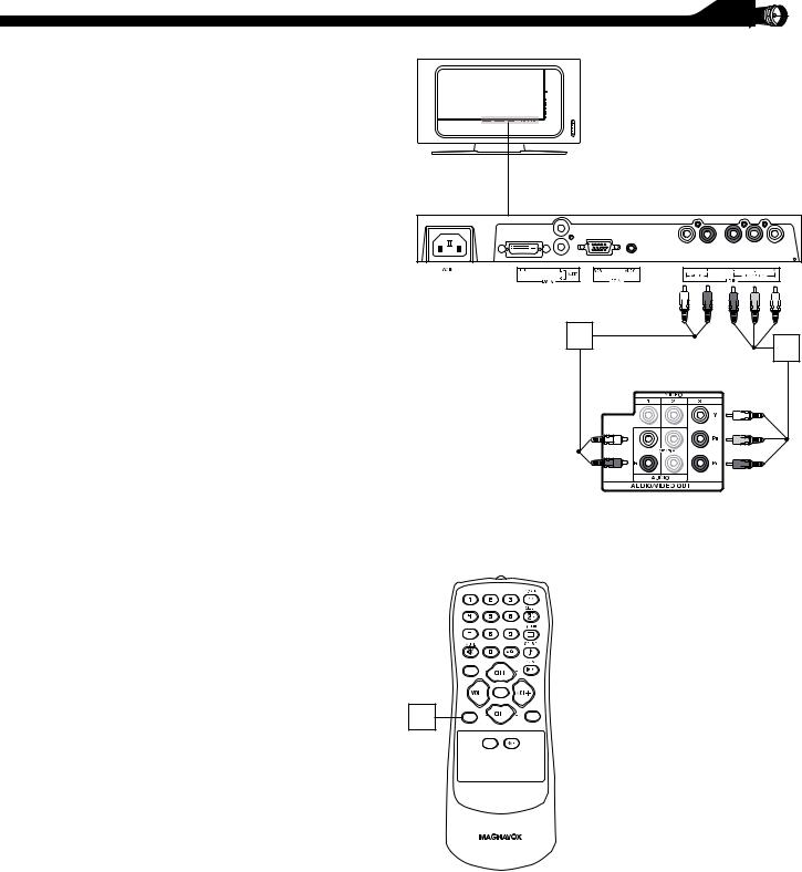
DIGITALTV RECEIVER,OR A DIGITAL SATELLITE RECEIVER
WITH HD (HIGH DEFINITION) OUTPUT
ADigitalTV Receiver or a Digital Satellite Receiver is able to produces HD (High
Definition) video signal with 480p, 720p, and 1080i formats.A Component (Y Pb, Pr) Connection is required for this kind of setup.
Note: This setup also support 480i.
Disconnect all power sources before making any connections.
1 |
Using a Component Video cable, connect |
|
|
|
the Digital TV Receiver’s Y, Pb, Pr jacks to |
|
the Y, Pb, Pr jacks on the TV. Use the HD |
|
IN connections. |
|
Note: Component Video (Y, Pb, Pr) |
2 |
|
|
connections in HD IN connections is |
1 |
|
|
necessary to view 480p, 720p, and 1080i |
|
|
|
formats. Note that the Component Video |
|
|
|
Input in AV IN 3 Connections can only |
|
|
2 |
support 480i format. |
|
|
Using an Audio cable, connect the Digital |
|
|
|
|
|
|
|
|
TV Receiver’s AUDIO OUT jacks to |
|
|
|
the TV’s AUDIO IN jacks in HD IN |
|
|
|
connections. |
Digital Satellite Receiver with HD output |
|
|
|
||
3Use Source button on the remote control to select HD to watch DVD.
Note: 1. The Y, Pb, Pr jacks do not provide audio, so audio cables must be connected to provide sound.
MENU
|
|
OK |
3 |
SOURCE |
PIP |
CC
13
 Loading...