


DFX SERIES OWNER’S MANUAL
DFX•6 AND DFX•12
6- AND 12-CHANNEL MIXERS WITH DIGITAL EFFECTS
DFX12 MIXER
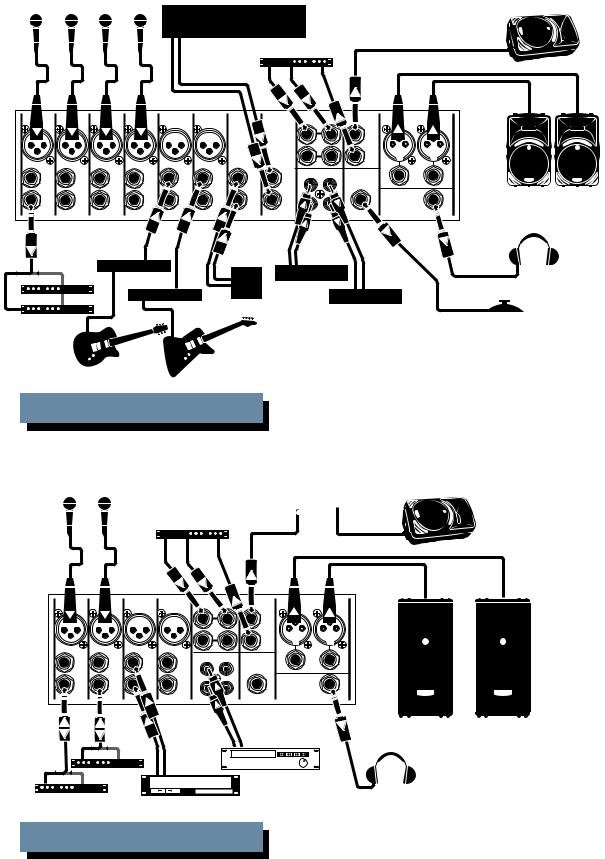
12 CHANNEL COMPACT INTEGRATED LIVE SOUND MIXER
OPTIONAL USES FOR INSERTS
CAUTION
RISK OF ELECTRIC SHOCK
DO NOT OPEN
REPLACE WITH THE SAME TYPE FUSE AND RATING.
DISCONNECT SUPPLY CORD BEFORE CHANGING FUSE
POWER
WARNING: TO REDUCE THE RISK OF FIRE OR ELECTRIC SHOCK, DO NOT |
SERIAL NUMBER |
MANUFACTURING DATE |
MONO PLUG |
STEREO |
EXPOSE THIS EQUIPMENT TO RAIN OR MOISTURE. DO NOT REMOVE COVER. |
|
|
|
PLUG |
NO USER SERVICEABLE PARTS INSIDE. REFER SERVICING TO QUALIFIED PERSONNEL. |
|
|
|
|
AVIS: RISQUE DE CHOC ELECTRIQUE — NE PAS OUVRIR |
|
|
INSERT ALL THE WAY IN TO |
TIP OUT TO EFFECTS DEVICE |
|
|
THE "SECOND CLICK" |
RING RETURN FROM EFFECTS |
|
UTILISE UN FUSIBLE DE RECHANGE DE MÊME TYPE. |
|
|
DIRECT OUT WITH SIGNAL |
FOR USE AS AN EFFECTS LOOP |
DEBRANCHER AVANT DE REMPLACER LE FUSIBLE |
|
|
INTERRUPTION TO MASTER |
(TIP= SEND, RING = RETURN) |
|
|
|
|
|
|
|
|
|
|
|
|
|
|
|
|
CONCEIVED AND DESIGNED BY MACKIE DESIGNS INC • WOODINVILLE • WA • USA • MADE IN CHINA •FABRIQUE AU CHINE • COPYRIGHT ©2001 • THE FOLLOWING |
|
||||||||||||||||
|
|
|
|
|
|
|
|
|
|
|
|
|
|
|
|
|
ARE TRADEMARKS OR REGISTERED TRADEMARKS OF MACKIE DESIGNS INC.: "MACKIE", "EMAC", AND THE "RUNNING MAN" FIGURE • PATENT PENDING |
|
|||||||||||||||
|
|
|
|
|
|
ON |
|
|
|
|
|
|
|
|
|
|
|
|
|
|
|
|
|
|
|
|
|
|
|
|
|
|
|
|
|
|
|
|
|
|
100 240 VAC, 50/60 Hz, |
|
|
|
|
|
|
|
|
|
|
|
|
|
|
|
|
|
|
|
|
|
|
|
|||
|
|
|
|
|
|
|
|
30 WATTS |
|
|
|
|
|
|
|
|
|
|
|
|
|
|
|
|
|
|
|
|
|
|
|
|
|
|
1 |
|
|
2 |
|
|
3 |
|
|
4 |
|
|
5/6 |
|
7/8 |
|
9/10 |
11/12 |
|
RETURN |
|
|
|
MAIN OUT |
|||||||||
|
|
|
|
|
|
|
|
|
|
|
|
|
|
|
|
|
|
|
|
|
|
|
|
|
L |
STEREO AUX |
AUX SEND |
||||||
|
MIC |
|
|
MIC |
|
|
MIC |
|
|
MIC |
|
|
MIC |
|
|
MIC |
|
|
|
|
|
|
|
|
1 |
|
R |
|
|
LEFT |
RIGHT |
||
|
|
|
|
|
|
|
|
|
|
|
|
|
|
|
|
|
|
|
|
|
|
|
1 |
||||||||||
|
|
|
|
|
|
|
|
|
|
|
|
|
|
|
|
|
|
|
|
|
|
|
|
|
|
|
|
|
|
|
|
||
|
|
|
|
|
|
|
|
|
|
|
|
|
|
|
|
|
|
|
|
|
|
|
|
|
|
|
|
|
|
|
|
|
|
|
|
|
|
|
|
|
|
|
|
|
|
|
|
|
|
|
|
|
|
|
|
|
|
|
|
|
|
|
|
|
MON |
|
|
|
|
|
|
|
|
|
|
|
|
|
|
|
|
|
|
|
|
|
|
|
|
|
|
|
(MONO) |
2 |
|
|
|
2 |
|
|
|
|
|
|
|
|
|
|
|
|
|
|
|
|
|
|
|
|
|
|
|
|
|
|
|
|
|
|
|
|
|
|
|
|
|
|
|
|
|
|
|
|
|
|
|
|
|
|
|
|
|
|
|
|
|
|
|
|
|
|
|
|
|
|
|
|
EFX |
|
|
BAL/UNBAL |
|
BAL/UNBAL |
|
BAL/UNBAL |
|
BAL/UNBAL |
|
BAL/UNBAL |
|
BAL/UNBAL |
|
BAL/UNBAL |
|
BAL/UNBAL |
|
|
|
|
|
|
|
|
|
|
|||||||||
|
|
|
|
|
|
|
|
|
|
|
|
|
|
|
|
|
|
|
|
|
|
|
|
|
CD/TAPE |
TAPE |
EFX |
|
|
|
|||
|
|
LINE IN |
|
|
LINE IN |
|
|
LINE IN |
|
|
LINE IN |
|
|
|
L |
|
|
L |
|
|
L |
|
|
L |
|
IN |
|
OUT |
FOOT |
|
|
|
|
|
|
|
|
|
|
|
|
|
|
|
|
|
|
(MONO) |
|
(MONO) |
|
(MONO) |
|
(MONO) |
L |
|
|
|
L |
SWITCH |
BAL/UNBAL |
|
|||||
|
|
|
|
|
|
|
|
|
|
|
|
|
|
LINE IN |
|
LINE IN |
|
LINE IN |
|
LINE IN |
|
|
|
|
|
|
|||||||
|
|
|
|
|
|
|
|
|
|
|
|
|
|
|
|
|
|
|
|
|
|
|
|
|
|
||||||||
|
|
INSERT |
|
|
INSERT |
|
|
INSERT |
|
|
INSERT |
|
|
|
R |
|
|
R |
|
|
R |
|
|
R |
R |
|
|
|
R |
|
|
PHONES |
|
|
|
|
|
|
|
|
|
|
|
|
|
|
|
|
|
|
|
|
|
|
|
|
|
|
|
|
|
|
|
|
|
||
LEVEL |
MIC |
1 |
LEVEL |
MIC |
2 |
LEVEL |
MIC |
3 |
LEVEL |
MIC |
4 |
LEVEL |
MIC |
5/6 |
LEVEL |
MIC |
7/8 |
LEVEL |
9/10 LEVEL |
11/12 |
|
|
|
|
DFX·12 |
|
POWER |
||||||
SET |
|
SET |
|
SET |
|
SET |
|
SET |
|
SET |
|
SET |
U |
|
SET |
U |
|
|
|
|
|
|
|||||||||||
|
U |
|
|
U |
|
|
U |
|
|
U |
|
|
U |
|
|
|
U |
|
|
|
|
|
|
|
|
|
|
|
|||||
|
|
|
|
|
|
|
|
|
|
|
|
|
|
|
|
|
|
|
|
|
|
|
|
|
|
|
|
|
|
|
|||
|
|
|
|
|
|
|
|
|
|
|
|
|
|
|
|
|
|
|
|
|
|
|
|
|
|
|
12 CHANNEL INTEGRATED LIVE SOUND MIXER |
|
|||||
MIN-20dB +30dB +50 |
MIN-20dB +30dB +50 |
MIN-20dB +30dB +50 |
MIN-20dB +30dB +50 |
MIN-20dB |
+20dB +40 |
MIN-20dB +20dB +40 |
-20dB +20dB |
-20dB +20dB |
+12 |
|
|
|
|
|
|
+12 |
|
||||||||||||||||
|
GAIN |
|
GAIN |
|
GAIN |
|
GAIN |
|
GAIN |
|
GAIN |
|
|
GAIN |
|
GAIN |
|
|
|
|
|
|
|
PHANTOM POWER |
|||||||||
|
|
|
|
|
|
|
|
|
|
|
|
|
|
|
|
|
|
|
|
|
|
|
|
|
|
|
|
|
|
|
|
||
LOW CUT |
|
LOW CUT |
|
LOW CUT |
|
LOW CUT |
|
|
|
|
|
|
|
|
|
|
|
|
|
|
|
|
|
|
|
|
|
|
+48V |
||||
|
75 Hz |
|
|
75 Hz |
|
|
75 Hz |
|
|
75 Hz |
|
|
|
|
|
|
|
|
|
|
|
|
|
|
|
|
|
|
|
|
|
|
|
|
U |
EQ |
|
U |
EQ |
|
U |
EQ |
|
U |
EQ |
|
U |
|
EQ |
|
U |
EQ |
|
U |
EQ |
|
U |
EQ |
0 |
|
|
|
|
|
|
0 |
|
|
|
|
|
|
|
|
|
|
|
|
|
|
|
|
|
LEFT RIGHT |
|||||||||||||||||
|
|
HI |
|
|
HI |
|
|
HI |
|
|
HI |
|
|
|
HI |
|
|
HI |
|
|
HI |
|
|
HI |
|
|
|
|
|
|
|
CLIP |
16 |
|
|
12k |
|
|
12k |
|
|
12k |
|
|
12k |
|
|
|
12k |
|
|
12k |
|
|
12k |
|
|
12k |
|
|
|
|
|
|
|
||
-15 |
+15 |
|
-15 |
+15 |
|
-15 |
+15 |
|
-15 |
+15 |
|
-15 |
+15 |
|
|
-15 |
+15 |
|
-15 |
+15 |
|
-15 |
+15 |
|
|
|
|
|
|
|
|
|
12 |
|
|
|
|
|
|
|
|
|
–12 |
|
|
|
|
|
|
–12 |
|
||||||||||||||||
|
U |
|
|
U |
|
|
U |
|
|
U |
|
|
U |
|
|
|
U |
|
|
U |
|
|
U |
|
60 |
|
|
250 |
1K |
3.5K |
8 |
||
|
|
LOW |
|
|
LOW |
|
|
LOW |
|
|
LOW |
|
|
|
LOW |
|
|
LOW |
|
|
LOW |
|
|
LOW |
|
|
|
12K |
4 |
||||
|
|
|
|
|
|
|
|
|
|
|
|
|
|
|
|
|
|
|
|
|
|
|
|
|
|||||||||
|
|
80Hz |
|
|
80Hz |
|
|
80Hz |
|
|
80Hz |
|
|
|
80Hz |
|
|
80Hz |
|
|
80Hz |
|
|
80Hz |
|
|
|
MAIN |
EQ |
BYPASS |
|
0 |
|
|
|
|
|
|
|
|
|
|
|
|
|
|
|
|
|
|
|
|
|
|
|
|
|
|
|
|
|
NORM |
|||||
-15 |
+15 |
|
-15 |
+15 |
|
-15 |
+15 |
|
-15 |
+15 |
|
-15 |
+15 |
|
|
-15 |
+15 |
|
-15 |
+15 |
|
-15 |
+15 |
|
|
|
|
AUX 1 |
|
|
|
4 |
|
|
|
AUX |
|
|
AUX |
|
|
AUX |
|
|
AUX |
|
|
|
AUX |
|
|
AUX |
|
|
AUX |
|
|
AUX |
|
|
|
|
|
DIGITAL STEREO |
BYPASS |
||
|
|
|
|
|
|
|
|
|
|
|
|
|
|
|
|
|
|
|
|
|
|
8 |
|||||||||||
|
|
1 |
|
|
1 |
|
|
1 |
|
|
1 |
|
|
|
1 |
|
|
1 |
|
|
1 |
|
|
1 |
|
|
|
|
EFFECTS PROCESSOR |
LEVEL SET |
|||
|
|
|
|
|
|
|
|
|
|
|
|
|
|
|
|
|
|
|
|
|
|
|
12 |
||||||||||
|
U MON |
|
U MON |
|
U |
MON |
|
U |
MON |
|
|
U MON |
|
U MON |
|
U |
MON |
|
U |
MON |
|
|
|
U |
REVERSE |
|
|
DELAY 1 |
16 |
||||
OO |
+6 |
|
OO |
+6 |
|
OO |
+6 |
|
OO |
+6 |
|
OO |
+6 |
|
|
OO |
+6 |
|
OO |
+6 |
|
OO |
+6 |
|
|
OO |
+6 |
|
GATE |
|
|
DELAY 2 |
|
|
|
|
|
|
|
|
|
|
|
|
CATHEDRAL |
|
|
DELAY 3 |
|
||||||||||||||||||
|
|
|
|
|
|
|
|
|
|
|
|
|
|
|
|
|
|
|
|
|
|
|
|
|
|
(EFFECTS TO |
|
|
20 |
||||
|
|
|
|
|
|
|
|
|
|
|
|
|
|
|
|
|
|
|
|
|
|
|
|
|
|
|
|
|
|
||||
|
|
2 |
|
|
2 |
|
|
2 |
|
|
2 |
|
|
|
2 |
|
|
2 |
|
|
2 |
|
|
2 |
STAGE MONITOR) |
LG. HALL |
|
|
DELAY 4 |
24 |
|||
|
|
|
|
|
|
|
|
|
|
|
|
|
|
|
|
|
|
|
|
|
|
|
|
|
|||||||||
|
U |
EFX |
|
U |
EFX |
|
U |
EFX |
|
U |
EFX |
|
|
U |
EFX |
|
U |
EFX |
|
U |
EFX |
|
U |
EFX |
|
|
|
|
MD. HALL |
|
|
CHORUS |
30 |
OO |
+6 |
|
OO |
+6 |
|
OO |
+6 |
|
OO |
+6 |
|
OO |
+6 |
|
|
OO |
+6 |
|
OO |
+6 |
|
OO |
+6 |
|
|
|
|
|
LG. PLATE |
|
|
FLANGE |
0 = +4dBu |
|
|
|
|
|
|
|
|
|
|
|
|
|
|
|
|
|
|||||||||||||||||
MD. PLATE |
PHASER |
SM. ROOM |
SPRING |
|
|
|
|
|
|
|
|
|
|
|
|
|
|
|
|
|
|
|
|
|
VOCAL |
|
|
|
|
|
|
|
|
|
|
|
|
|
|
|
|
|
|
|
|
|
|
ELIMINATOR |
|
|
|
|
|
|
|
|
|
|
|
|
|
|
|
|
|
|
|
U |
|
U |
|
|
|
|
|
|
|
|
|
|
|
|
|
|
|
|
|
|
|
OO |
+6 |
OO |
+6 |
BREAK |
|
L |
R |
L |
R |
L |
R |
L |
R |
L |
R |
L |
R |
L |
R |
L |
PAN |
R |
SWITCH |
OO MAX |
||||
|
PAN |
|
PAN |
|
PAN |
|
PAN |
|
PAN |
|
PAN |
|
PAN |
|
|
AUX 1/MON SEND |
AUX 2/EFX SEND |
(MUTES ALL MIC CHANNELS) |
PHONES |
|||
1 |
MUTE |
2 |
MUTE |
3 |
MUTE |
4 |
MUTE |
5 |
MUTE |
7 |
MUTE |
9 |
MUTE |
11 |
MUTE |
AUX 1 |
MUTE |
AUX 2/EFX |
MUTE |
CD/TAPE |
MUTE |
MAIN MIX |
|
|
|
|
/6 |
|
/8 |
|
/10 |
|
/12 |
|
RETURN |
|
RETURN |
|
RETURN |
|
LEFT RIGHT |
||||
dB |
|
dB |
|
dB |
|
dB |
|
dB |
|
dB |
|
dB |
|
dB |
|
dB |
|
dB |
|
dB |
|
dB |
10 |
|
10 |
|
10 |
|
10 |
|
10 |
|
10 |
|
10 |
|
10 |
|
10 |
|
10 |
|
10 |
|
10 |
|
OL |
|
OL |
|
OL |
|
OL |
|
OL |
|
OL |
|
OL |
|
OL |
|
|
|
|
|
|
|
5 |
5 |
5 |
5 |
5 |
5 |
5 |
5 |
5 |
5 |
5 |
5 |
U |
U |
U |
U |
U |
U |
U |
U |
U |
U |
U |
U |
5 |
5 |
5 |
5 |
5 |
5 |
5 |
5 |
5 |
5 |
5 |
5 |
10 |
10 |
10 |
10 |
10 |
10 |
10 |
10 |
10 |
10 |
10 |
10 |
20 |
20 |
20 |
20 |
20 |
20 |
20 |
20 |
20 |
20 |
20 |
20 |
30 |
30 |
30 |
30 |
30 |
30 |
30 |
30 |
30 |
30 |
30 |
30 |
40 |
40 |
40 |
40 |
40 |
40 |
40 |
40 |
40 |
40 |
40 |
40 |
50 |
50 |
50 |
50 |
50 |
50 |
50 |
50 |
50 |
50 |
50 |
50 |
60 |
60 |
60 |
60 |
60 |
60 |
60 |
60 |
60 |
60 |
60 |
60 |
OO |
OO |
OO |
OO |
OO |
OO |
OO |
OO |
OO |
OO |
OO |
OO |
CAUTION AVIS
RISK OF ELECTRIC SHOCK
DO NOT OPEN
RISQUE DE CHOC ELECTRIQUE
NE PAS OUVRIR
CAUTION: TO REDUCE THE RISK OF ELECTRIC SHOCK
DO NOT REMOVE COVER (OR BACK)
NO USER-SERVICEABLE PARTS INSIDE
REFER SERVICING TO QUALIFIED PERSONNEL
ATTENTION: POUR EVITER LES RISQUES DE CHOC ELECTRIQUE, NE PAS ENLEVER LE COUVERCLE. AUCUN ENTRETIEN DE PIECES INTERIEURES PAR L'USAGER. CONFIER L'ENTRETIEN AU PERSONNEL QUALIFIE.
AVIS: POUR EVITER LES RISQUES D'INCENDIE OU D'ELECTROCUTION, N'EXPOSEZ PAS CET ARTICLE A LA PLUIE OU A L'HUMIDITE
The lightning flash with arrowhead symbol within an equilateral triangle is intended to alert the user to the presence of uninsulated "dangerous voltage" within the product's enclosure that may be
of sufficient magnitude to constitute a risk of electric shock to persons.
Le symbole éclair avec point de flèche à l'intérieur d'un triangle équilatéral est utilisé pour alerter l'utilisateur de la présence à l'intérieur du coffret de "voltage dangereux" non isolé d'ampleur suffisante pour constituer un risque d'éléctrocution.
The exclamation point within an equilateral triangle is intended to alert the user of the presence of important operating and maintenance (servicing) instructions in the literature accompanying the appliance.
Le point d'exclamation à l'intérieur d'un triangle équilatéral est employé pour alerter les utilisateurs de la présence d'instructions importantes pour le fonctionnement et l'entretien (service) dans le livret d'instruction accompagnant l'appareil.
SAFETY INSTRUCTIONS
1.Read Instructions — All the safety and operation instructions should be read before this Mackie product is operated.
2.Retain Instructions — The safety and operating instructions should be kept for future reference.
3.Heed Warnings — All warnings on this Mackie product and in these operating instructions should be followed.
4.Follow Instructions — All operating and other instructions should be followed.
5.Water and Moisture — This Mackie product should not be used near water
– for example, near a bathtub, washbowl, kitchen sink, laundry tub, in a wet basement, near a swimming pool, swamp or salivating St. Bernard dog, etc.
6.Cleaning — Clean only with a dry cloth.
7.Ventilation — This Mackie product should be situated so that its location or position does not interfere with its proper ventilation. For example, the Component should not be situated on a bed, sofa, rug, or similar surface that may block any ventilation openings, or placed in a built-in installation such as a bookcase or cabinet that may impede the flow of air through ventilation openings.
8.Heat — This Mackie product should be situated away from heat sources such as radiators, or other devices which produce heat.
9.Power Sources — This Mackie product should be connected to a power supply only of the type described in these operation instructions or as marked on this Mackie product.
10.Power Cord Protection — Power supply cords should be routed so that they are not likely to be walked upon or pinched by items placed upon or against them, paying particular attention to cords at plugs, convenience receptacles, and the point where they exit this Mackie product.
11.Object and Liquid Entry — Care should be taken so that objects do not fall on, and liquids are not spilled into, this Mackie product.
12.Damage Requiring Service — This Mackie product should be serviced only by qualified service personnel when:
A.The power-supply cord or the plug has been damaged; or
B.Objects have fallen, or liquid has spilled into this Mackie product; or
C.This Mackie product has been exposed to rain; or
D.This Mackie product does not appear to operate normally or exhibits a marked change in performance; or
E.This Mackie product has been dropped, or its chassis damaged.
13.Servicing — The user should not attempt to service this Mackie product beyond those means described in this operating manual. All other servicing should be referred to the Mackie Service Department.
14.To prevent electric shock, do not use this polarized plug with an extension cord, receptacle or other outlet unless the blades can be fully inserted to prevent blade exposure.
Pour prévenir les chocs électriques ne pas utiliser cette fiche polariseé avec un prolongateur, un prise de courant ou une autre sortie de courant, sauf si les lames peuvent être insérées à fond sans laisser aucune pariie à découvert.
15.Grounding or Polarization — Precautions should be taken so that the grounding or polarization means of this Mackie product is not defeated.
16.Power Precaution — Unplug this Mackie product during lightning storms or when unused for long periods of time.
17.This apparatus does not exceed the Class A/Class B (whichever is applicable) limits for radio noise emissions from digital apparatus as set out in the radio interference regulations of the Canadian Department of Communications.
ATTENTION —Le présent appareil numérique n’émet pas de bruits radioélectriques dépassant las limites applicables aux appareils numériques de class A/de class B (selon le cas) prescrites dans le règlement sur le brouillage radioélectrique édicté par les ministere des communications du Canada.
18. Exposure to extremely high noise levels may cause permanent hearing loss. Individuals vary considerably in susceptibility to noise-induced hearing loss, but nearly everyone will lose some hearing if exposed to sufficiently intense noise for a period of time. The U.S. Government’s Occupational Safety and Health Administration (OSHA) has specified the permissible noise level exposures shown in the following chart.
According to OSHA, any exposure in excess of these permissible limits could result in some hearing loss. To ensure against potentially dangerous exposure to high sound pressure levels, it is recommended that all persons exposed to equipment capable of producing high sound pressure levels use hearing protectors while the equipment is in operation. Ear plugs or protectors in the ear canals or over the ears must be worn when operating the equipment in order to prevent a permanent hearing loss if exposure is in excess of the limits set forth here.
Duration Per Day |
Sound Level dBA, |
Typical |
In Hours |
Slow Response |
Example |
8 |
90 |
Duo in small club |
6 |
92 |
|
4 |
95 |
Subway Train |
3 |
97 |
|
2 |
100 |
Very loud classical music |
1.5 |
102 |
|
1 |
105 |
Patrice screaming at Ron about deadlines |
0.5 |
110 |
|
0.25 or less |
115 |
Loudest parts at a rock concert |
|
|
|
WARNING — To reduce the risk of fire or electric shock, do not expose this appliance to rain or moisture.
2

About this manual:
This manual covers both the DFX•6 and DFX•12 mixers. They share the same design and operate in the same way, except that the DFX•12 has 2 more mono channels than the DFX•6, and it has 2 stereo line-only channels.
Absolutely most important pages:
Before connecting and using your mixer, please read the Safety Instructions on page 2. Before you start mixing, please read the Quick Start section starting on page 4. It’s a list of steps that will familiarize you with the mixer and help you
set up a basic performance.
CONTENTS
SAFETY INSTRUCTIONS ....................... |
page 2 |
MASTER SECTION FEATURES |
|
|
QUICK START ............................................. |
4 |
STEREO GRAPHIC EQ .................. |
page 14 |
|
INTRODUCTION .......................................... |
6 |
MAIN/AUX 1 EQ SWITCH ................... |
|
15 |
APPLICATION DIAGRAMS ............................ |
7 |
BYPASS EQ SWITCH ............................ |
|
15 |
PATCHBAY FEATURES |
|
POWER LED ....................................... |
|
15 |
|
PHANTOM POWER SWITCH AND LED ... |
15 |
||
MIC .................................................... |
8 |
METERS ............................................ |
|
15 |
LINE IN (MONO) .................................. |
8 |
PHONES LEVEL ................................... |
|
15 |
LINE IN (STEREO) ................................. |
8 |
MAIN MIX FADERS ............................. |
|
15 |
INSERT ................................................ |
9 |
CD/TAPE RETURN FADER AND MUTE .... |
15 |
|
EFFECTS: SERIAL OR PARALLEL? ............. |
9 |
BREAK SWITCH .................................. |
|
16 |
MAIN OUTPUTS ................................. |
10 |
VOCAL ELIMINATOR SWITCH ............... |
|
16 |
PHONES ............................................ |
10 |
AUX 2/EFX SEND ............................... |
|
16 |
AUX SEND 1/MON ............................ |
10 |
LEVEL SET LED .................................... |
|
16 |
AUX SEND 2/EFX ............................... |
10 |
AUX 2/EFX RETURN FADER AND MUTE 17 |
||
AUX 1 RETURN .................................. |
11 |
AUX 1/MON SEND ............................ |
|
17 |
AUX 2 RETURN .................................. |
11 |
EFFECTS TO MONITOR ........................ |
|
17 |
CD/TAPE INPUT ................................. |
11 |
AUX 1 RETURN FADER AND MUTE ....... |
|
17 |
TAPE OUTPUT .................................... |
11 |
EMAC EFFECTS PROCESSOR ................. |
|
17 |
EFX FOOTSWITCH ............................... |
11 |
QUICK START .................................. |
|
17 |
AC POWER INPUT .............................. |
11 |
BYPASS LED .................................... |
|
17 |
POWER SWITCH ................................ |
11 |
PRESET SELECTION ........................... |
|
18 |
CHANNEL STRIP FEATURES |
|
APPENDIX A: SERVICE INFO |
|
|
GAIN ................................................ |
12 |
WARRANTY SERVICE .......................... |
|
20 |
LEVEL SET LED .................................... |
12 |
TROUBLESHOOTING ........................... |
|
20 |
LOW CUT .......................................... |
12 |
REPAIR ............................................. |
|
20 |
2-BAND EQ ........................................ |
12 |
APPENDIX B: TECHNICAL INFO |
|
|
HI EQ ............................................. |
12 |
|
|
|
LOW EQ ......................................... |
12 |
SPECIFICATIONS ................................. |
|
21 |
AUXILIARIES ...................................... |
13 |
DIMENSIONS ..................................... |
|
22 |
AUX 1/MON .................................. |
13 |
AC POWER CONSIDERATIONS .............. |
|
22 |
AUX 2/EFX ..................................... |
13 |
BLOCK DIAGRAM ............................... |
|
23 |
PAN .................................................. |
13 |
|
|
|
MUTE ................................................ |
13 |
|
|
|
FADER ............................................... |
13 |
|
|
|
OL OVERLOAD LED ............................. |
13 |
|
|
|
Please visit our website at www.mackie.com
for more information about this and other Mackie products.
3

QUICK START
We know you can’t wait to get the show on the road. Who has time to read a booooring manual? That’s fine — the DFX Mixer is designed to set up quickly and operate intuitively — but please, read the Safety Instructions on page 2, and then read these two pages!
First you will zero the console, then make the connections, set the levels and tweak the mix.
1. ZERO THE CONSOLE:
1.Turn everything off, including the mixer’s POWER switch and PHANTOM POWER switch.
2.Turn down the channel strip GAIN, AUX 1 and AUX 2 knobs, and faders.
3.Center the channel strip EQ and PAN controls.
4.Push the channel strip MUTE switches down.
5.Set the channel strip LOW CUT switches up.
6.Center the STEREO GRAPHIC EQ sliders.
7.Turn down the MASTER AUX SEND knobs, and the AUX RETURN faders.
8.Turn down the MAIN MIX faders.
9.Now you are ready to make the connections, see the next page.
|
1 |
|
|
2 |
|
|
3 |
|
|
4 |
|
|
5/6 |
|
7/8 |
|
9/10 |
11/12 |
|
RETURN |
|
AUX SEND |
MAIN OUT |
||||||||||
|
|
|
|
|
|
|
|
|
|
|
|
|
|
|
|
|
|
|
|
|
|
|
|
|
|
STEREO AUX |
|
|
|||||
|
MIC |
|
|
MIC |
|
|
MIC |
|
|
MIC |
|
|
MIC |
|
|
MIC |
|
|
|
|
|
|
|
|
L |
|
1 |
|
R |
|
|
LEFT |
RIGHT |
|
|
|
|
|
|
|
|
|
|
|
|
|
|
|
|
|
|
|
|
|
|
|
|
1 |
|||||||||
|
|
|
|
|
|
|
|
|
|
|
|
|
|
|
|
|
|
|
|
|
|
|
|
|
|
|
|
|
|
|
|
||
|
|
|
|
|
|
|
|
|
|
|
|
|
|
|
|
|
|
|
|
|
|
|
|
|
|
|
|
|
|
|
|
|
|
|
|
|
|
|
|
|
|
|
|
|
|
|
|
|
|
|
|
|
|
|
|
|
|
|
|
|
|
|
|
|
MON |
|
|
|
|
|
|
|
|
|
|
|
|
|
|
|
|
|
|
|
|
|
|
|
|
|
|
|
(MONO) |
2 |
|
|
|
2 |
|
|
|
|
|
|
|
|
|
|
|
|
|
|
|
|
|
|
|
|
|
|
|
|
|
|
|
|
|
|
|
|
|
|
|
|
|
|
|
|
|
|
|
|
|
|
|
|
|
|
|
|
|
|
|
|
|
|
|
|
|
|
|
|
|
|
|
|
EFX |
|
|
BAL/UNBAL |
|
BAL/UNBAL |
|
BAL/UNBAL |
|
BAL/UNBAL |
|
BAL/UNBAL |
|
BAL/UNBAL |
|
BAL/UNBAL |
|
BAL/UNBAL |
|
|
|
|
|
|
|
|
|
|
|||||||||
|
|
|
|
|
|
|
|
|
|
|
|
|
|
|
|
|
|
|
|
|
|
|
|
|
CD/TAPE |
TAPE |
EFX |
|
|
|
|||
|
|
|
|
|
|
|
|
|
|
|
|
|
|
L |
|
|
L |
|
|
|
L |
|
|
L |
|
IN |
|
OUT |
|
|
|
||
|
|
LINE IN |
|
LINE IN |
|
|
LINE IN |
|
LINE IN |
|
|
|
|
|
|
|
|
|
|
|
FOOT |
|
|
|
|||||||||
|
|
|
|
|
|
|
|
|
|
|
|
|
(MONO) |
|
(MONO) |
|
|
(MONO) |
|
(MONO) |
L |
|
|
|
L |
SWITCH |
BAL/UNBAL |
|
|||||
|
|
|
|
|
|
|
|
|
|
|
|
|
LINE IN |
|
LINE IN |
|
|
LINE IN |
|
LINE IN |
|
|
|
|
|
|
|||||||
|
|
|
|
|
|
|
|
|
|
|
|
|
|
|
|
|
|
|
|
|
|
|
|
|
|
||||||||
|
|
INSERT |
|
|
INSERT |
|
|
INSERT |
|
|
INSERT |
|
|
R |
|
|
R |
|
|
|
R |
|
|
R |
R |
|
|
|
R |
|
|
PHONES |
|
|
|
|
|
|
|
|
|
|
|
|
|
|
|
|
|
|
|
|
|
|
|
|
|
|
|
|
|
|
|
|
|
||
LEVEL |
MIC |
1 |
LEVEL |
MIC |
2 |
LEVEL |
MIC |
3 LEVEL |
MIC |
4 LEVEL |
MIC |
5/6 LEVEL |
MIC |
7/8 LEVEL |
|
9/10 LEVEL |
11/12 |
|
|
|
|
DFX·12 |
|
POWER |
|||||||||
SET |
U |
|
SET |
U |
|
SET |
U |
|
SET |
U |
|
SET |
U |
|
SET |
U |
|
SET |
U |
|
|
SET |
U |
|
|
|
|
|
|
||||
|
|
|
|
|
|
|
|
|
|
|
|
|
|
|
|
|
|
|
|
|
|
|
|
|
|
|
|
|
|
|
|||
|
|
|
|
|
|
|
|
|
|
|
|
|
|
|
|
|
|
|
|
|
|
|
|
|
|
|
12 CHANNEL INTEGRATED LIVE SOUND MIXER |
|
|||||
MIN-20dB +30dB +50 |
MIN-20dB +30dB +50 |
MIN-20dB +30dB +50 |
MIN-20dB +30dB +50 |
MIN-20dB +20dB +40 |
MIN-20dB +20dB +40 |
-20dB |
+20dB |
-20dB +20dB |
+12 |
|
|
|
|
|
|
+12 |
|
||||||||||||||||
|
GAIN |
|
GAIN |
|
GAIN |
|
GAIN |
|
GAIN |
|
GAIN |
|
GAIN |
|
GAIN |
|
|
|
|
|
|
|
PHANTOM POWER |
||||||||||
|
|
|
|
|
|
|
|
|
|
|
|
|
|
|
|
|
|
|
|
|
|
|
|
|
|
|
|
|
|
|
|
||
LOW CUT |
|
LOW CUT |
|
LOW CUT |
|
LOW CUT |
|
|
|
|
|
|
|
|
|
|
|
|
|
|
|
|
|
|
|
|
|
|
+48V |
||||
|
75 Hz |
|
|
75 Hz |
|
|
75 Hz |
|
|
75 Hz |
|
|
|
|
|
|
|
|
|
|
|
|
|
|
|
|
|
|
|
|
|
|
|
|
U |
EQ |
|
U |
EQ |
|
U |
EQ |
|
U |
EQ |
|
U |
EQ |
|
U |
EQ |
|
U |
|
EQ |
|
U |
EQ |
0 |
|
|
|
|
|
|
0 |
|
|
|
|
|
|
|
|
|
|
|
|
|
|
|
|
|
LEFT RIGHT |
|||||||||||||||||
|
|
HI |
|
|
HI |
|
|
HI |
|
|
HI |
|
|
HI |
|
|
HI |
|
|
|
HI |
|
|
HI |
|
|
|
|
|
|
|
CLIP |
16 |
|
|
12k |
|
|
12k |
|
|
12k |
|
|
12k |
|
|
12k |
|
|
12k |
|
|
|
12k |
|
|
12k |
|
|
|
|
|
|
|
||
|
|
|
|
|
|
|
|
|
|
|
|
|
|
|
|
|
|
|
|
|
|
|
|
|
|
||||||||
-15 |
+15 |
|
-15 |
+15 |
|
-15 |
+15 |
|
-15 |
+15 |
|
-15 |
+15 |
|
-15 |
+15 |
|
-15 |
+15 |
|
|
-15 |
+15 |
|
|
|
|
|
|
|
|
|
12 |
|
|
|
|
|
|
|
|
|
–12 |
|
|
|
|
|
|
–12 |
|
||||||||||||||||
|
U |
|
|
U |
|
|
U |
|
|
U |
|
|
U |
|
|
U |
|
|
U |
|
|
|
U |
|
60 |
|
|
250 |
1K |
3.5K |
8 |
||
|
|
LOW |
|
|
LOW |
|
|
LOW |
|
|
LOW |
|
|
LOW |
|
|
LOW |
|
|
|
LOW |
|
|
LOW |
|
|
|
12K |
4 |
||||
|
|
|
|
|
|
|
|
|
|
|
|
|
|
|
|
|
|
|
|
|
|
|
|
|
|||||||||
|
|
80Hz |
|
|
80Hz |
|
|
80Hz |
|
|
80Hz |
|
|
80Hz |
|
|
80Hz |
|
|
|
80Hz |
|
|
80Hz |
|
|
|
MAIN |
EQ |
BYPASS |
NORM |
0 |
|
|
|
|
|
|
|
|
|
|
|
|
|
|
|
|
|
|
|
|
|
|
|
|
|
|
|
|
|
||||||
-15 |
+15 |
|
-15 |
+15 |
|
-15 |
+15 |
|
-15 |
+15 |
|
-15 |
+15 |
|
-15 |
+15 |
|
-15 |
+15 |
|
|
-15 |
+15 |
|
|
|
|
AUX 1 |
|
|
|
|
|
|
|
AUX |
|
|
AUX |
|
|
AUX |
|
|
AUX |
|
|
AUX |
|
|
AUX |
|
|
|
AUX |
|
|
AUX |
|
|
|
|
|
DIGITAL STEREO |
BYPASS |
4 |
|
|
|
|
|
|
|
|
|
|
|
|
|
|
|
|
|
|
|
|
|
|
|
8 |
|||||||||||
|
|
1 |
|
|
1 |
|
|
1 |
|
|
1 |
|
|
1 |
|
|
1 |
|
|
|
1 |
|
|
1 |
|
|
|
|
EFFECTS PROCESSOR |
LEVEL SET |
|||
|
|
|
|
|
|
|
|
|
|
|
|
|
|
|
|
|
|
|
|
|
|
|
12 |
||||||||||
|
|
|
|
|
U |
|
|
|
|
|
|
|
|
U |
|
|
|
|
|
U |
|
|
|
|
|||||||||
|
U MON |
|
U MON |
|
MON |
|
U |
MON |
|
U MON |
|
U MON |
|
|
MON |
|
U |
MON |
|
|
|
REVERSE |
|
|
DELAY 1 |
16 |
|||||||
OO |
+6 |
|
OO |
+6 |
|
OO |
+6 |
|
OO |
+6 |
|
OO |
+6 |
|
OO |
+6 |
|
OO |
+6 |
|
|
OO |
+6 |
|
|
OO |
+6 |
|
GATE |
|
|
DELAY 2 |
|
|
|
|
|
|
|
|
|
|
|
|
CATHEDRAL |
|
|
DELAY 3 |
|
||||||||||||||||||
|
|
|
|
|
|
|
|
|
|
|
|
|
|
|
|
|
|
|
|
|
|
|
|
|
|
(EFFECTS TO |
|
|
20 |
||||
|
|
|
|
|
|
|
|
|
|
|
|
|
|
|
|
|
|
|
|
|
|
|
|
|
|
|
|
|
|
||||
|
|
2 |
|
|
2 |
|
|
2 |
|
|
2 |
|
|
2 |
|
|
2 |
|
|
|
2 |
|
|
2 |
STAGE MONITOR) |
LG. HALL |
|
|
DELAY 4 |
24 |
|||
|
U |
|
U |
|
U |
|
U |
|
U |
|
U |
|
|
U |
|
U |
|
|
|
|
MD. HALL |
|
|
CHORUS |
|||||||||
|
EFX |
|
EFX |
|
EFX |
|
EFX |
|
EFX |
|
EFX |
|
|
EFX |
|
EFX |
|
|
|
|
|
|
30 |
||||||||||
OO |
+6 |
|
OO |
+6 |
|
OO |
+6 |
|
OO |
+6 |
|
OO |
+6 |
|
OO |
+6 |
|
OO |
+6 |
|
|
OO |
+6 |
|
|
|
|
|
LG. PLATE |
|
|
FLANGE |
|
|
|
|
|
|
|
|
|
|
|
|
|
|
|
|
|
|
|
|
|
|
|
|
|
|
|
|
|
|
MD. PLATE |
|
|
PHASER |
0 = +4dBu |
|
|
|
|
|
|
|
|
|
|
|
|
|
|
|
|
|
|
|
|
|
|
|
|
|
|
|
|
|
|
|
|
||
SM. ROOM |
SPRING |
|
|
|
|
|
|
|
|
|
|
|
|
VOCAL |
|
|
|
|
|
|
|
|
|
|
|
|
|
ELIMINATOR |
|
|
|
|
|
|
|
|
|
|
U |
|
U |
|
|
|
|
|
|
|
|
|
|
OO |
+6 |
OO |
+6 |
BREAK |
OO MAX |
L PAN R |
L PAN R |
L PAN R |
L PAN R |
L PAN R |
L PAN R |
L PAN R |
L PAN R |
SWITCH |
|||||
AUX 1/MON SEND |
AUX 2/EFX SEND |
(MUTES ALL MIC CHANNELS) |
PHONES |
||||||||||
1 |
MUTE |
|
2 |
MUTE |
|
3 |
MUTE |
|
4 |
MUTE |
|
5/6 |
MUTE |
|
7/8 |
MUTE |
|
9/10 |
MUTE |
|
11/12 |
MUTE |
|
AUX 1 |
MUTE |
AUX 2/EFX |
MUTE |
CD/TAPE |
MUTE |
|
MAIN MIX |
|
|
|
|
|
|
|
|
RETURN |
RETURN |
RETURN |
|
LEFT RIGHT |
|||||||||||||||||||
|
|
|
|
|
|
|
|
|
|
|
|
|
|
|
|
|
|
|
|
|
|
|
|
|
|
|
|
|
|
|
|
dB |
dB |
dB |
dB |
dB |
dB |
dB |
dB |
dB |
dB |
dB |
dB |
10 |
10 |
10 |
10 |
10 |
10 |
10 |
10 |
10 |
10 |
10 |
10 |
|
OL |
OL |
OL |
OL |
OL |
OL |
OL |
OL |
|
|
|
5 |
5 |
5 |
5 |
5 |
5 |
5 |
5 |
5 |
5 |
5 |
5 |
U |
U |
U |
U |
U |
U |
U |
U |
U |
U |
U |
U |
5 |
5 |
5 |
5 |
5 |
5 |
5 |
5 |
5 |
5 |
5 |
5 |
10 |
10 |
10 |
10 |
10 |
10 |
10 |
10 |
10 |
10 |
10 |
10 |
20 |
20 |
20 |
20 |
20 |
20 |
20 |
20 |
20 |
20 |
20 |
20 |
30 |
30 |
30 |
30 |
30 |
30 |
30 |
30 |
30 |
30 |
30 |
30 |
40 |
40 |
40 |
40 |
40 |
40 |
40 |
40 |
40 |
40 |
40 |
40 |
50 |
50 |
50 |
50 |
50 |
50 |
50 |
50 |
50 |
50 |
50 |
50 |
60 |
60 |
60 |
60 |
60 |
60 |
60 |
60 |
60 |
60 |
60 |
60 |
OO |
OO |
OO |
OO |
OO |
OO |
OO |
OO |
OO |
OO |
OO |
OO |
Zeroing the console
4 |
Key to the control settings |

2. MAKE THE CONNECTIONS:
1.Connect your amplifier’s outputs to your speaker inputs (unless, of course, you have powered monitors).
2.Plug all the sound system components into suitable AC outlets, properly grounded and capable of delivering adequate current.
3.Using XLR or 1/4" TRS cables, make connections from your mixer’s MAIN OUT to your amplification system’s line inputs.
4.Make connections from your microphones and instruments to the mixer: Connect balanced microphones to the mono channel MIC jacks. (For condenser microphones, engage the PHANTOM POWER switch, located just above the meters). Connect line-level instruments (synthesizers, guitar effects, direct boxes) to the mono or stereo channel LINE IN 1/4" TRS jacks.
5.ZERO THE CONSOLE as shown on the previous page.
6.Turn all the power switches on, leaving the amplifier’s switch for last.
7.Turn up the MAIN MIX faders to the “–30” label, for now. We’ll crank it later on.
8.Now you are ready to set the levels:
3. SET THE LEVELS:
1.Choose one of the microphones or instruments you connected. Make some noise. If it’s a microphone, sing at your normal singing volume. If it’s a synthesizer, play it at its normal output level.
2.While making noise, turn up that channel’s GAIN control until the adjacent LEVEL SET LED starts a-blinking.
3.Disengage (up) that channel’s MUTE.
4.Raise that channel’s fader to unity gain (“U” label). You should be hearing your noise now.
5.If necessary, apply channel EQ changes. (You may need to compensate for level changes with the channel fader.)
6.Check that the channel’s OL LED does not come on. If it does, reset the GAIN and adjust the EQ if required.
7.Repeat steps 1 through 6 for the remaining active channels.
8.Stop making noise. Everyone: start making music.
9.Now you are ready to tweak the mix:
4. TWEAK THE MIX:
1.Engage MUTE on all channels except your rhythm section (drums & bass).
2.Adjust the rhythm section’s channel faders to get a good balance of levels.
3.Un-mute the other active channels and adjust their faders.
4.Now that you have a rough mix going, turn up the MAIN MIX faders to a comfortable listening level.
5.If the overall mix has an equalization problem, make adjustments to the STEREO GRAPHIC EQ. If an individual channel is the problem, use its channel EQ instead.
6.Use the channel AUX 2/EFX knobs to send signals to the EMAC internal effects processor (and to any external effects processor you might have). Then adjust the AUX 2/EFX RETURN fader and experiment with adding some effects to your main mix.
7.If you are playing into the CD/TAPE input, try using the VOCAL ELIMINATOR to hear its effect on centered vocals and start up a bit of audience mass-Karaoke.
8.Depending on how much time you’ve got, keep tweaking. Walk the room to see how it sounds away from your mixer.
Keep tweaking.
KNOW THESE THINGS:
• Never listen to loud music for prolonged periods. Please see “Safety Instructions” on page 2 for information on hearing protection.
•Never plug amplifier outputs into anything except speakers.
•Never use guitar cables to connect amplifiers to speakers.
•Before making connections to an external amp or reconfiguring an amp’s routing, turn the amp’s level (gain) controls down, turn the power off, make the changes, turn the power back on, and then turn the level controls back up.
•When you shut down your equipment, turn off any external amplifiers first. When powering up, turn on the amplifiers last.
•Change your engine oil every 3,000 miles and rotate your tires for even wear. Dad would be proud of you.
•Save the shipping box and packing material! You may need them someday, and you probably don’t want to have to pay for that again.
5

INTRODUCTION
Thank you for choosing a Mackie Designs DFX™ Mixer! These compact live-sound mixers are designed to meet the sound reinforcement needs of almost any small to medium-sized club, meeting room, sanctuary, or outdoor gathering. Here’s a quick glance at all the features
you’ve acquired:
2 or 4 mono channels, with:
•Variable input gain
(0 to +50 dB mic, –20 to +30 dB line)
•Phantom power (globally switched)
•Level Set gain-setting indicator LED
•XLR microphone input jack
•1/4" TRS line input jack
•1/4" TRS insert jack
•Switchable 75 Hz low-cut filter
•Pre-fader aux (monitor) send
•Post-fader aux (effects) send
•2-band EQ
•Pan control
•Mute switch
•Overload warning LED
•60mm mono fader
2 mono-mic / stereo-line channels, with:
•Variable input gain
(0 to +40 dB mic, –20 to +20 dB line)
•Level Set gain-setting indicator LED
•XLR microphone input jack
•Left and Right 1/4" TRS line input jacks
•Pre-fader aux (monitor) send
•Post-fader aux (effects) send
•2-band EQ
•Pan control
•Mute switch
•Overload warning LED
•60mm stereo fader
The DFX•12 also includes:
2 stereo-line channels, with:
•Variable input gain (–20 to +20 dB line)
•Level Set gain-setting indicator LED
•Left and Right TRS line input jacks
•Pre-fader aux (monitor) send
•Post-fader aux (effects) send
•2-band EQ
•Pan control
•Mute switch
•Overload warning LED
•60mm stereo fader
Comprehensive master section, with:
•Two 60mm main mix faders (L, R)
•Balanced XLR stereo main outputs
•Balanced TRS stereo main outputs
•12-segment stereo LED metering
•5-band stereo graphic EQ with main mix/ monitor switch and bypass switch
•EMAC™ 32-bit digital stereo effects with footswitch bypass, and Level Set LED
•Aux 1/monitor send with level control
•Aux 2/effects send with level control
•Effects-to-monitor control
•Two 60mm stereo aux return faders with mute switches
•Break switch for intermissions
•RCA Tape output
•RCA CD/Tape input
•Vocal Eliminator circuit for CD/Tape
•Master +48 V phantom power switch with LED indicator
•Headphone output with level control
•Power LED indicator
Please write your serial number here for future reference (i.e., insurance claims, tech support, return authorization, etc.):
Purchased at:
Date of purchase:
Part No. 0000318 Rev. D 09/02
©2002 Mackie Designs Inc. All Rights Reserved.
6
APPLICATION
DIAGRAMS
Microphones 1-4 |
Active Monitor |
Mono in/Stereo out Reverb (optional)
1 |
2 |
3 |
|
4 |
5/6 |
7/8 |
9/10 |
11/12 |
|
RETURN |
|
AUX SEND |
MAIN OUT |
|||
|
|
|
|
|
|
|
|
|
L |
STEREO AUX |
R |
|
|
|||
MIC |
MIC |
MIC |
|
MIC |
MIC |
MIC |
|
|
|
1 |
|
|
LEFT |
RIGHT |
||
|
|
|
|
|
|
|
1 |
|||||||||
|
|
|
|
|
|
|
|
|
|
|
|
|
|
|
||
|
|
|
|
|
|
|
|
|
|
|
|
|
|
|
|
|
|
|
|
|
|
|
|
|
|
|
|
|
|
|
MON |
|
|
|
|
|
|
|
|
|
|
|
|
(MONO) |
2 |
|
|
2 |
|
|
|
|
|
|
|
|
|
|
|
|
|
|
|
|
|
|
|
|
|
|
|
|
|
|
|
|
|
|
|
|
|
EFX |
|
|
BAL/UNBAL |
BAL/UNBAL |
BAL/UNBAL |
|
BAL/UNBAL |
BAL/UNBAL |
BAL/UNBAL |
BAL/UNBAL |
BAL/UNBAL |
|
|
|
|
|
|
|
|
|
|
|
|
|
|
|
|
|
|
CD/TAPE |
TAPE |
|
EFX |
|
|
|
|
|
|
|
|
L |
L |
L |
L |
|
IN |
|
OUT |
|
|
|
|
LINE IN |
|
LINE IN |
LINE IN |
LINE IN |
|
|
|
FOOT |
|
|
||||||
|
|
|
|
|
(MONO) |
(MONO) |
(MONO) |
(MONO) |
L |
|
|
L |
SWITCH |
BAL/UNBAL |
|
|
|
|
|
|
|
LINE IN |
LINE IN |
LINE IN |
LINE IN |
|
|
|
|
||||
|
|
|
|
|
|
|
|
|
|
|
|
|
||||
INSERT |
|
INSERT |
INSERT |
INSERT |
R |
R |
R |
R |
R |
|
|
R |
|
PHONES |
Active Speakers (SRM450s) |
|
|
|
|
|
|
|
|
|
|
|
|
|
|
|
|||
 Insert
Headphones
Reverb |
Mono Effects |
|
Tape Player |
|
|
|
|
(optional) |
|
|
Drum Machine |
|
|
|
|
Compressor |
|
|
DAT Recorder |
Guitar |
Bass |
Foot Switch |
|
|
|
|
DFX•12 — Small Club Gig
Microphones |
Amplifier (M1400) |
Passive Monitor (C300) |
|||
|
|
|
|
|
|
|
|
|
|
|
|
|
|
|
|
|
|
Mono in/Stereo out Reverb (optional)
1 |
|
2 |
3/4 |
5/6 |
|
STEREO AUX |
|
AUX SEND |
MAIN OUT |
|||
|
L |
RETURN |
R |
|
||||||||
MIC |
|
MIC |
MIC |
MIC |
|
1 |
|
|
LEFT |
RIGHT |
||
|
|
|
|
|
1 |
|||||||
|
|
|
|
|
|
|
|
|
|
|
||
|
|
|
|
|
|
|
|
|
|
|
|
|
|
|
|
|
|
|
|
|
|
|
MON |
|
|
|
|
|
|
|
|
(MONO) |
2 |
|
|
2 |
|
|
|
|
|
|
|
|
|
|
|
|
|
|
|
|
|
|
|
|
|
|
|
|
|
EFX |
|
|
BAL/UNBAL |
BAL/UNBAL |
BAL/UNBAL |
BAL/UNBAL |
|
|
|
|
|
|
|
|
|
|
|
|
|
|
|
CD/TAPE |
TAPE |
|
EFX |
|
|
|
|
LINE IN |
LINE IN |
L |
L |
|
IN |
|
OUT |
|
FOOT |
|
|
|
|
|
(MONO) |
(MONO) |
L |
|
|
L |
SWITCH |
|
BAL/UNBAL |
|
|
|
|
LINE IN |
LINE IN |
|
|
|
|
||||
|
|
|
|
|
|
|
|
|
|
|
||
|
INSERT |
INSERT |
R |
R |
R |
|
|
R |
|
PHONES |
||
|
|
|
|
|
|
|
|
|
|
|||
Insert |
Insert |
|
|
|
|
|
|
|
|
|
||
SR1530
Active Speakers
Compressors |
CD/DVD Player |
|
(optional) |
||
Routed through |
||
|
Vocal Eliminator |
Headphones |
Laser Disc /DVD Player
DFX•6 — Karaoke set up
7
PATCHBAY (the intro and the outro)
This is where everything gets plugged in: microphones, line-level instruments, effects devices, and the ultimate destination(s): PA system, monitors, headphones, and tape recorder, etc.
1 |
2 |
3 |
|
4 |
5/6 |
7/8 |
9/10 |
11/12 |
|
RETURN |
|
AUX SEND |
MAIN OUT |
|||
|
|
|
|
|
|
|
|
|
L |
STEREO AUX |
R |
|
|
|||
MIC |
MIC |
MIC |
|
MIC |
MIC |
MIC |
|
|
|
1 |
|
|
LEFT |
RIGHT |
||
|
|
|
|
|
|
|
1 |
|||||||||
|
|
|
|
|
|
|
|
|
|
|
|
|
|
|
||
|
|
|
|
|
|
|
|
|
|
|
|
|
|
|
|
|
|
|
|
|
|
|
|
|
|
|
|
|
|
|
MON |
|
|
|
|
|
|
|
|
|
|
|
|
(MONO) |
2 |
|
|
2 |
|
|
|
|
|
|
|
|
|
|
|
|
|
|
|
|
|
|
|
|
|
|
|
|
|
|
|
|
|
|
|
|
|
EFX |
|
|
BAL/UNBAL |
BAL/UNBAL |
BAL/UNBAL |
|
BAL/UNBAL |
BAL/UNBAL |
BAL/UNBAL |
BAL/UNBAL |
BAL/UNBAL |
|
|
|
|
|
|
|
|
|
|
|
|
|
|
|
|
|
|
CD/TAPE |
TAPE |
|
EFX |
|
|
|
|
|
|
|
|
L |
L |
L |
L |
|
IN |
|
OUT |
|
|
|
|
LINE IN |
|
LINE IN |
LINE IN |
LINE IN |
|
|
|
FOOT |
|
|
||||||
|
|
|
|
|
(MONO) |
(MONO) |
(MONO) |
(MONO) |
L |
|
|
L |
SWITCH |
|
BAL/UNBAL |
|
|
|
|
|
|
LINE IN |
LINE IN |
LINE IN |
LINE IN |
|
|
|
|
||||
|
|
|
|
|
|
|
|
|
|
|
|
|
||||
INSERT |
|
INSERT |
INSERT |
INSERT |
R |
R |
R |
R |
R |
|
|
R |
|
PHONES |
||
|
|
|
|
|
|
|
|
|
|
|
|
|
|
|||
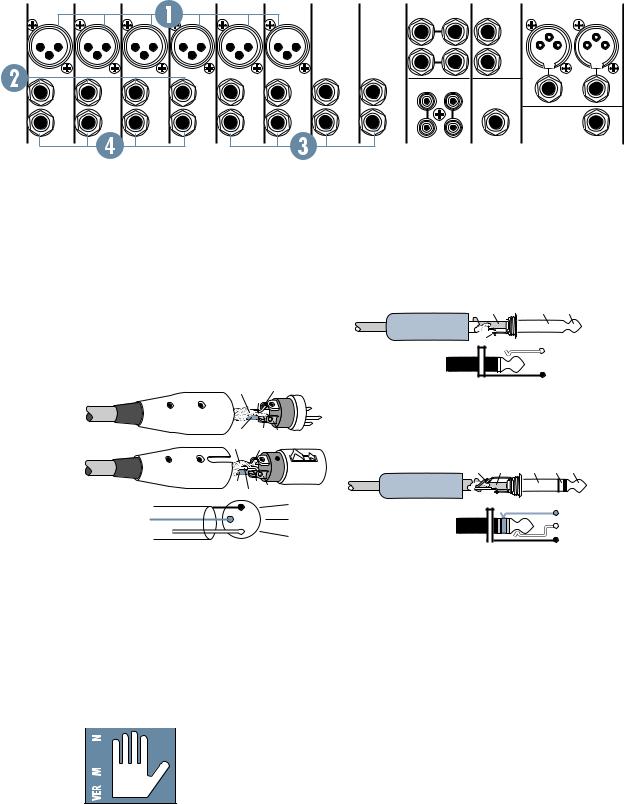
1. MIC
The DFX Mixer is equipped with rugged, low noise, phantom-powered microphone preamplifiers, providing up to 50 dB of pounding crystal-clear amplification. Their balanced circuitry rejects all manner of extraneous interference. Professional condenser, dynamic, and ribbon mics all sound excellent through these XLR inputs.
You can plug in almost any kind of balanced mic that has a standard XLR-type male mic connector.
SHIELD |
|
2 |
|
HOT |
|
COLD |
3 |
1 |
SHIELD |
1 |
|
COLD |
3 |
2 |
HOT |
|
|
1 |
|
SHIELD |
3 |
|
COLD |
2 |
|
HOT |
|
|
|
2. LINE IN (FOR MONO CHANNELS)
These inputs can accept 1/4" TRS balanced and 1/4" TS unbalanced plugs from any linelevel instrument, effects device, or tape player. The line inputs share circuitry (but not phantom power) with the mic preamps, and can be driven by virtually any line-level signal.
SLEEVE |
SLEEVE |
TIP |
|
|
|
|
|
|
|
|
|
|
|
|
|
TIP
TIP
SLEEVE
1/4" TS (Tip-Sleeve) unbalanced wiring: Tip = hot (+)
Sleeve = shield
RING SLEEVE |
SLEEVE RING TIP |
TIP
RING |
TIP |
SLEEVE |
XLR balanced wiring:
Pin 1 = shield
Pin 2 = hot (+)
Pin 3 = cold (–)
The DFX Mixers provide +48 VDC phantom powering on pins 2 and 3 of all the mono channels’ XLR MIC inputs (not the stereo channels). This can be turned on or off using the PHANTOM POWER (31) switch on the right side of the mixer.  DO NOT connect a line-
  level device to a MIC input
  with the phantom power
  switched on. This could
damage the device. Use the LINE IN (2, 3) jacks instead.
8
1/4" TRS (Tip-Ring-Sleeve) balanced wiring:
Tip = hot (+) Ring = cold (–) Sleeve = shield
3. LINE IN (FOR STEREO CHANNELS)
These inputs can accept 1/4" TRS balanced and 1/4" TS unbalanced plugs from any linelevel instrument, effects device, or tape player.
When connecting a stereo device (two cords), use both the left (mono) input and the right input.
When connecting a mono device (just one cord), always use the left (mono) input and plug nothing into the right input. A trick called “jack normalling” causes the signal to appear on both sides.
 Loading...