


 MICROSERIES1202 OWNER’S MANUAL
|
MIC 1 |
|
MIC 2 |
|
MIC 3 |
|
MIC 4 |
LEFT/MONO |
RIGHT |
|
|
|
|
|
|
|
L |
|
|
|
|
|
|||||
|
|
|
|
|
1 |
|
|
|
1 |
|
|
|
|
|
|
|
|
|
|||||||||
|
|
|
|
|
|
|
|
|
|
|
|
|
|
|
|
|
|
|
|
|
L |
|
|
MICRO SERIES 1202 |
|||
|
|
|
|
|
|
|
|
|
|
|
|
|
|
|
|
|
|
|
|
|
|
|
|
||||
|
|
|
|
|
|
|
|
|
|
|
|
|
|
|
|
|
|
|
|
|
|
|
12-CHANNEL MIC/LINE MIXER |
||||
|
|
|
|
|
|
|
|
|
|
|
|
|
2 |
|
|
|
2 |
|
|
|
R |
R |
|
|
|
|
|
|
|
|
|
|
|
|
|
|
|
|
|
|
|
|
|
|
|
|
|
|
|
|
|
|
|
|
|
|
|
|
|
|
|
|
|
|
|
|
|
STEREO AUX RETURNS |
AUX OUT |
TAPE |
TAPE |
MAIN OUTS |
|
|
|
|
|
||||||
|
|
|
|
|
|
|
|
|
|
|
|
INPUT |
OUTPUT |
|
|
|
|
|
|||||||||
|
LINE1 |
|
LINE 2 |
|
LINE 3 |
|
LINE 4 |
|
|
L |
|
|
L |
|
|
L |
|
L |
|
|
|
|
|
||||
|
|
|
|
|
|
MONO |
|
|
MONO |
|
|
MONO |
|
MONO |
|
|
|
|
|
||||||||
|
BAL/UNBAL |
|
BAL/UNBAL |
|
BAL/UNBAL |
|
BAL/UNBAL |
|
|
|
|
|
|
|
|
|
|
|
|
|
|
|
|
||||
|
ITY |
|
ITY |
|
ITY |
|
ITY |
|
|
|
|
|
|
|
|
|
|
|
|
|
|
|
|
||||
|
IV |
|
|
IV |
|
|
IV |
|
|
IV |
|
|
|
|
|
|
|
|
|
|
|
|
|
|
|
|
|
|
IT |
|
|
IT |
|
|
IT |
|
|
IT |
|
|
|
|
|
|
|
|
|
|
|
|
|
|
|
|
|
|
S |
|
|
S |
|
|
S |
|
|
S |
|
|
|
|
|
|
|
|
|
|
|
|
|
|
|
|
|
E |
N |
–10 |
E |
N |
–10 |
E |
N |
–10 |
E |
N |
–10 |
|
|
|
|
|
|
|
|
|
|
|
|
|
|
|
|
S |
|
S |
|
S |
|
S |
|
|
|
|
|
|
|
|
|
|
|
|
|
|
|
|
|
||||
|
+4 |
40dB |
|
+4 |
40dB |
|
+4 |
40dB |
|
+4 |
40dB |
|
|
R |
|
|
R |
|
|
R |
|
R |
|
|
|
|
|
|
|
|
|
|
|
|
|
|
|
|
|
|
|
|
|
|
|
|
|
||||||||
|
U |
GAIN |
|
U |
GAIN |
|
U |
GAIN |
|
U |
GAIN |
LINE 5-6 |
|
|
LINE 7-8 |
LINE 9-10 |
LINE 11-12 |
|
PHONES |
|
|
||||||
|
TRIM 1 |
|
TRIM 2 |
|
TRIM 3 |
|
TRIM 4 |
|
|
|
|
|
|||||||||||||||
|
|
U |
|
|
U |
|
|
U |
|
|
U |
|
U |
|
|
|
U |
|
U |
|
|
U |
|
|
|
|
U |
|
|
1 |
|
|
1 |
|
|
1 |
|
|
1 |
|
|
1 |
|
|
1 |
|
|
1 |
|
1 |
|
|
|
|
1 |
|
OO |
+15 |
|
OO |
+15 |
|
OO |
+15 |
|
OO |
+15 |
OO |
+15 |
|
|
OO |
+15 |
OO |
+15 |
|
OO |
+15 |
|
|
|
OO |
+20 |
|
|
U |
|
|
U |
|
|
U |
|
|
U |
|
U |
|
|
|
U |
|
U |
|
|
U |
|
TAPE IN |
|
|
U |
|
|
|
|
|
|
|
|
|
|
|
|
|
|
|
|
|
|
|
|
|
|
|
|
AUX 2 |
|
|
|
|
|
2 |
|
|
2 |
|
|
2 |
|
|
2 |
|
|
2 |
|
|
2 |
|
|
2 |
|
2 |
|
|
|
|
2 |
|
OO |
+15 |
|
OO |
+15 |
|
OO |
+15 |
|
OO |
+15 |
OO |
+15 |
|
|
OO |
+15 |
OO |
+15 |
|
OO |
+15 |
|
|
|
OO |
+20 |
|
AUX |
|
AUX |
|
AUX |
|
AUX |
AUX |
|
|
AUX |
AUX |
|
AUX |
|
STEREO AUX RETURN TO MASTER |
|||||||||||
|
|
|
|
|
|
|
|
|
|
|
|
|
|
|
|
|
|
|
|
|
|
|
|
+22 |
CLIP |
TRIM |
LINE IN |
|
|
|
|
|
|
|
|
|
|
|
|
|
|
|
|
|
|
|
|
|
|
|
|
1-4 |
1-12 |
||
|
|
HI |
|
|
HI |
|
|
HI |
|
|
HI |
|
|
HI |
|
|
HI |
|
|
HI |
|
HI |
|
+10 |
|
|
|
|
|
|
|
|
|
|
|
|
|
|
|
|
|
|
|
+7 |
|
INPUT CH. |
|||||||||
|
–15 |
+15 |
|
–15 |
+15 |
|
–15 |
+15 |
|
–15 |
+15 |
–15 |
+15 |
|
|
–15 |
+15 |
–15 |
+15 |
|
–15 |
+15 |
|
|
|||
|
|
|
|
|
|
|
|
|
|
|
|
|
|
|
|
|
|
|
|
|
|
|
|
+4 |
|
METERING |
|
|
|
|
|
|
|
|
|
|
|
|
|
|
|
|
|
|
|
|
|
|
|
|
|
|
|
|
|
|
|
|
|
|
|
|
|
|
|
|
|
|
|
|
|
|
|
|
|
|
|
|
|
+2 |
|
|
|
|
|
|
|
|
|
|
|
|
|
|
|
|
|
|
|
|
|
|
|
|
|
|
|
0 |
0dBu |
POWER |
|
|
|
LO |
|
|
LO |
|
|
LO |
|
|
LO |
|
|
LO |
|
|
LO |
|
|
LO |
|
LO |
|
CAL. |
|
|
|
|
|
|
|
|
|
|
|
|
|
|
|
|
|
|
|
|
|
|
|||||||||
|
–15 |
+15 |
|
–15 |
+15 |
|
–15 |
+15 |
|
–15 |
+15 |
–15 |
+15 |
|
|
–15 |
+15 |
–15 |
+15 |
|
–15 |
+15 |
|
-2 |
|
|
|
|
EQ |
|
EQ |
|
EQ |
|
EQ |
EQ |
|
|
EQ |
EQ |
|
EQ |
|
-4 |
|
|
|
||||||||
|
|
|
|
|
|
|
|
|
|
|
|
|
|
|
|
|
|
|
|
|
|
|
|
|
|
|
|
|
|
|
|
|
|
|
|
|
|
|
|
|
|
|
|
|
|
|
|
|
|
|
|
-7 |
|
|
|
|
|
|
|
|
|
|
|
|
|
|
|
|
|
|
|
|
|
|
|
|
|
|
|
-10 |
|
|
|
|
L R |
|
L R |
|
L R |
|
L R |
L R |
|
|
L R |
L R |
|
L R |
|
-20 |
|
|
|
||||||||
|
|
|
|
|
|
|
|
|
|
|
|
||||||||||||||||
|
PAN |
|
PAN |
|
PAN |
|
PAN |
PAN |
|
|
PAN |
PAN |
|
PAN |
|
-30 |
|
|
|
||||||||
|
|
|
|
|
|
|
|
|
|
|
|
|
|
|
|
|
|
|
|
|
|
|
U |
|
|
|
|
|
|
U |
|
|
U |
|
|
U |
|
|
U |
|
U |
|
|
|
U |
|
U |
|
|
U |
BAL. |
U |
|
|
|
OO |
+20 |
OO |
+20 |
OO |
+20 |
OO |
+20 |
OO |
+20 |
OO |
+20 |
OO |
|
+20 |
OO |
+20 |
|
OO |
+10 |
OO |
|
||||||
|
GAIN 1 |
|
GAIN 2 |
|
GAIN 3 |
|
GAIN 4 |
GAIN 5-6 |
GAIN 7-8 |
GAIN 9-10 |
GAIN 11-12 |
|
MASTER |
PHONES |
|||||||||||||
|
|
|
|
|
|
|
|
|
|
|
|
|
|
|
|
|
|
|
|
|
|
1 |
|
|
|
|
|
CAUTION AVIS
RISK OF ELECTRIC SHOCK
DO NOT OPEN
RISQUE DE CHOC ELECTRIQUE
NE PAS OUVRIR
CAUTION: TO REDUCE THE RISK OF ELECTRIC SHOCK
DO NOT REMOVE COVER (OR BACK)
NO USER-SERVICEABLE PARTS INSIDE
REFER SERVICING TO QUALIFIED PERSONNEL
ATTENTION: POUR EVITER LES RISQUES DE CHOC ELECTRIQUE, NE PAS ENLEVER LE COUVERCLE. AUCUN ENTRETIEN DE PIECES INTERIEURES PAR L'USAGER. CONFIER L'ENTRETIEN AU PERSONNEL QUALIFIE.
AVIS: POUR EVITER LES RISQUES D'INCENDIE OU D'ELECTROCUTION, N'EXPOSEZ PAS CET ARTICLE A LA PLUIE OU A L'HUMIDITE
The lightning flash with arrowhead symbol within an equilateral triangle is intended to alert the user to the presence of uninsulated "dangerous voltage" within the product's enclosure, that may be
of sufficient magnitude to constitute a risk of electric shock to persons.
Le symbole éclair avec point de flèche à l'intérieur d'un triangle équilatéral est utilisé pour alerter l'utilisateur de la présence à l'intérieur du coffret de "voltage dangereux" non isolé d'ampleur suffisante pour constituer un risque d'éléctrocution.
The exclamation point within an equilateral triangle is intended to alert the user of the presence of important operating and maintenance (servicing) instructions in the literature accompanying the appliance.
Le point d'exclamation à l'intérieur d'un triangle équilatéral est employé pour alerter les utilisateurs de la présence d'instructions importantes pour le fonctionnement et l'entretien (service) dans le livret d'instruction accompagnant l'appareil.
SAFETY INSTRUCTIONS
1.Read Instructions — All the safety and operation instructions should be read before the MicroSeries 1202 is operated.
2.Retain Instructions — The safety and operating instructions should be kept for future reference.
3.Heed Warnings — All warnings on the MicroSeries 1202 and in these operating instructions should be followed.
4.Follow Instructions — All operating and other instructions should be followed.
5.Water and Moisture — The MicroSeries 1202 should not be used near water—for example, near a bathtub, washbowl, kitchen sink, laundry tub, in a wet basement, near a swimming pool, swamp or salivating St. Bernard dog, etc.
6.Heat — The MicroSeries 1202 should be situated away from heat sources such as radiators, or other devices which produce heat.
7.Power Sources — The MicroSeries 1202 should be connected to a power supply only of the type described in these operation instructions or as marked on the MicroSeries 1202.
V 2.4 –1/95
8.Power Cord Protection — Power supply cords should be routed so that they are not likely to be walked upon or pinched by items placed upon or against them, paying particular attention to cords at plugs, convenience receptacles, and the point where they exit the MicroSeries 1202.
9.Object and Liquid Entry — Care should be taken so that objects do not fall into and liquids are not spilled into the inside of the MicroSeries 1202.
10.Damage Requiring Service — The MicroSeries 1202 should be serviced only by qualified service personnel when:
A.The power-supply cord or the plug has been damaged; or
B.Objects have fallen, or liquid has spilled into the MicroSeries 1202; or
C.The MicroSeries 1202 has been exposed to rain; or
D.The MicroSeries 1202 does not appear to operate normally or exhibits a marked change in performance; or
E.The MicroSeries 1202 has been dropped, or its chassis damaged.
11.Servicing — The user should not attempt to service the MicroSeries 1202 beyond those means described in this operating manual. All other servicing should be referred to the Mackie Service Department.
12.To prevent electric shock, do not use this polarized plug with an extension cord, receptacle or other outlet unless the blades can be fully inserted to prevent blade exposure.
Pour préevenir les chocs électriques ne pas utiliser cette fiche polariseé avec un prolongateur, un prise de courant ou une autre sortie de courant, sauf si les lames peuvent être insérées à fond sans laisser aucune pariie à découvert.
13. Grounding or Polarization — Precautions should be taken so that the grounding or polarization means of the MicroSeries 1202 is not defeated.
14.This apparatus does not exceed the Class A/Class B (whichever is applicable) limits for radio noise emissions from digital apparatus as set out in the radio interference regulations of the Canadian Department of Communications.
ATTENTION —Le présent appareil numérique n’émet pas de bruits radioélectriques dépassant las limites applicables aux appareils numériques de class A/de class B (selon le cas) prescrites dans le règlement sur le brouillage radioélectrique édicté par les ministere des communications du Canada.
WARNING — To reduce the risk of fire or electric shock, do not expose this appliance to rain or moisture.
2

Fast-Track “CAN’T WAIT!” tips for people who ignore manuals
A.To adjust input levels:
1.Set TRIM fully counterclockwise.
2.Set GAIN to unity (twelve o’clock).
3.Push in the INPUT CH. METERING switch.
4.Feed a normal signal into a selected input.
5.Adjust that input’s TRIM control so that the display on the left LED strip stays around 0, and never goes higher than +10.
6.Repeat for each of Channels 1– 4.
B.Connecting effects
Read the section starting on page 11 for full information on connecting digital delays, reverbs, etc. via AUX SENDS and STEREO AUX RETURNS. This can get pretty complicated quickly.
Don’t cream your monitor speakers
Always turn the master gain and headphone level controls down before making connections to and from your MS 1202.
PATCHBAY DESCRIPTION
BEGINS ON PG. 4
CHANNEL STRIP & OUTPUT SECTION DESCRIPTION, PG. 8
CONNECTION TIPS &
HOOK-UP , PG. 11
DETAILED LEVEL-SETTING
PROCEDURE, PG. 12
1202 BLOCK DIAGRAM & SERVICE INFO PG. 13-15
INTRODUCTION
Thank you! There are a lot of makes and models out there, all competing for your bucks … but you have voted with your wallet for the folks in Woodinville who specialize in American-made mixers.
There are only two other things we ask: First, now that you’ve got a MicroSeries 1202, find out how to get the most from it.
That’s where this manual comes in.
•If this is your first pro mixer, flip through the whole book: you’ll find it full of actual from-the-streets engineering tips, as well as operation and installation instructions.
•If you’re an experienced, big-bucks engineer with lots of fader hours under your fingertips, at least read “Part 1: All the Holes and Knobs.” (We’ve found that experienced engineers usually read manuals cover-to-cover anyway so that they can keep getting the big bucks.)
PATCH
BAY
1202 CONTROLS
HOOK
UP
LEVEL
SETTING
STEPS
TECH
STUFF
3

Part 1 — ALL THE HOLES AND KNOBS:
A GUIDED TOUR OF THE MICROSERIES 1202
The first thing you’ll notice is that the top panel is organized into three distinct areas:
•A patchbay along the top;
•Eight channel strips — four mono and four stereo;
•And an output section on the right.
Note that four patchbay jacks overflowed the top panel, and are on the rear of the
MS 1202. The following pictures will help you find everything; the next few pages will help you use it all.
PATCHBAY
At the risk of stating the obvious, this is where you plug everything in: microphones, line-level instruments and effects, headphones, and the ultimate destination for your sound: a tape recorder, PA system, etc.
1 Microphone Inputs
We use true “phantom-powered, balanced inputs” just like the big studio mega-con- soles, for exactly the same reason: this kind
of circuit is excellent at rejecting hum and noise. You can plug any kind of professional mic that has a standard “XLR-type” male mic connector. If you wire your own, connect them like this:
Pin 1 = Ground or shield
Pin 2 = Hot (in phase with output) Pin 3 = Cold (out of phase with output)
Professional ribbon, dynamic and condenser mics will all sound excellent through these inputs, especially if you follow the Level Setting instructions on page 12. Lowercost electret-type unbalanced mics can be plugged into Line Inputs 1–12, but will require additional gain.
Basically, the MS 1202’s inputs will handle any kind of mic level you can toss at them without overloading. But you’ll get the absolute best quality sound if you follow the calibration procedure covered briefly in our “Can’t Wait Tips” on page 3, and more depth in Part 3, page 12.
|
MIC 1 |
|
MIC 2 |
|
MIC 3 |
|
MIC 4 |
LEFT/MONO |
RIGHT |
|
|
|
|
|
|
|
|
L |
|
|
|
|
|
|||||
|
|
|
|
|
1 |
|
|
|
|
1 |
|
|
|
|
|
|
|
|
|
|||||||||
|
|
|
|
|
|
|
|
|
|
|
|
|
|
|
|
|
|
|
|
|
|
L |
|
|
MICRO SERIES 1202 |
|||
|
|
|
|
|
|
|
|
|
|
|
|
|
|
|
|
|
|
|
|
|
|
|
|
12-CHANNEL MIC/LINE MIXER |
||||
|
|
|
|
|
|
|
|
|
|
|
|
|
2 |
|
|
|
|
2 |
|
|
|
R |
R |
|
|
|
|
|
|
|
|
|
|
|
|
|
|
|
|
|
|
|
|
|
|
|
|
|
|
|
|
|
|
|
|
|
|
|
|
|
|
|
|
|
|
|
|
|
|
STEREO AUX RETURNS |
AUX OUT |
TAPE |
TAPE |
MAIN OUTS |
|
|
|
|
|
|||||||
|
|
|
|
|
|
|
|
|
|
|
|
INPUT |
OUTPUT |
|
|
|
|
|
||||||||||
|
LINE1 |
|
LINE 2 |
|
LINE 3 |
|
LINE 4 |
|
|
L |
|
|
|
L |
|
|
L |
|
L |
|
|
|
|
|
||||
|
|
|
|
|
|
MONO |
|
|
|
MONO |
|
|
MONO |
|
MONO |
|
|
|
|
|
||||||||
|
|
|
PATCHBAY |
|
|
|
|
|
|
|
|
|
|
|
|
|
|
|||||||||||
|
BAL/UNBAL |
|
BAL/UNBAL |
|
BAL/UNBAL |
|
BAL/UNBAL |
|
|
|
|
|
|
|
|
|
|
|
|
|
|
|
|
|
||||
|
|
Y |
|
|
Y |
|
|
Y |
|
|
Y |
|
|
|
|
|
|
|
|
|
|
|
|
|
|
|
|
|
|
IVIT |
|
IVIT |
|
IVIT |
|
IVIT |
|
|
|
|
|
|
|
|
|
|
|
|
|
|
|
|
|
||||
|
IT |
|
|
IT |
|
|
IT |
|
|
IT |
|
|
|
|
|
|
|
|
|
|
|
|
|
|
|
|
|
|
|
S |
|
|
S |
|
|
S |
|
|
S |
|
|
|
|
|
|
|
|
|
|
|
|
|
|
|
|
|
|
E |
N |
–10 |
E |
N |
–10 |
E |
N |
–10 |
E |
N |
–10 |
|
|
|
|
|
|
|
|
|
|
|
|
|
|
|
|
|
S |
|
S |
|
S |
|
S |
|
|
|
|
|
|
|
|
|
|
|
|
|
|
|
|
|
|
||||
|
+4 |
40dB |
|
+4 |
40dB |
|
+4 |
40dB |
|
+4 |
40dB |
|
|
R |
|
|
|
R |
|
|
R |
|
R |
|
|
|
|
|
|
|
|
|
|
|
|
|
|
|
|
|
|
|
|
|
|
|
|
|
|
||||||||
|
U |
GAIN |
|
U |
GAIN |
|
U |
GAIN |
|
U |
GAIN |
LINE 5-6 |
|
|
LINE 7-8 |
|
LINE 9-10 |
LINE 11-12 |
|
PHONES |
|
|
||||||
|
TRIM 1 |
|
TRIM 2 |
|
TRIM 3 |
|
TRIM 4 |
|
|
|
|
|
|
|||||||||||||||
|
|
U |
|
|
U |
|
|
U |
|
|
U |
|
U |
|
|
|
U |
|
|
U |
|
|
U |
|
|
|
|
U |
|
|
1 |
|
|
1 |
|
|
1 |
|
|
1 |
|
|
1 |
|
|
|
1 |
|
|
1 |
|
1 |
|
|
|
|
1 |
|
OO |
+15 |
|
OO |
+15 |
|
OO |
+15 |
|
OO |
+15 |
OO |
+15 |
|
|
OO |
+15 |
|
OO |
+15 |
|
OO |
+15 |
|
|
|
OO |
+20 |
|
|
U |
|
|
U |
|
|
U |
|
|
U |
|
U |
|
|
|
U |
|
|
U |
|
|
U |
|
TAPE IN |
|
|
U |
|
|
|
|
|
|
|
|
|
|
|
|
|
|
|
|
|
|
|
|
|
|
|
|
|
AUX 2 |
|
|
|
|
|
2 |
|
|
2 |
|
|
2 |
|
|
2 |
|
|
2 |
|
|
|
2 |
|
|
2 |
|
2 |
|
|
|
|
2 |
|
OO |
+15 |
|
OO |
+15 |
|
OO |
+15 |
|
OO |
+15 |
OO |
+15 |
|
|
OO |
+15 |
|
OO |
+15 |
|
OO |
+15 |
|
|
|
OO |
+20 |
|
AUX |
|
AUX |
|
AUX |
|
AUX |
AUX |
|
|
AUX |
|
AUX |
|
AUX |
|
STEREO AUX RETURN TO MASTER |
|||||||||||
|
|
|
|
|
|
|
|
|
|
|
|
|
|
|
|
|
|
|
|
|
|
|
|
|
+22 |
CLIP |
TRIM |
LINE IN |
|
|
|
|
|
|
|
|
|
|
|
|
|
|
|
|
|
|
|
|
|
|
|
|
|
1-4 |
1-12 |
||
|
|
HI |
|
|
HI |
|
|
HI |
|
|
HI |
|
|
HI |
|
|
|
HI |
|
|
HI |
|
HI |
|
+10 |
|
|
|
|
|
|
|
|
|
|
|
|
|
|
|
|
|
|
|
|
+7 |
|
INPUT CH. |
|||||||||
|
–15 |
+15 |
|
–15 |
+15 |
|
–15 |
+15 |
|
–15 |
+15 |
–15 |
+15 |
|
|
–15 |
+15 |
|
–15 |
+15 |
|
–15 |
+15 |
|
|
|||
|
|
|
|
|
|
|
|
CHANNEL STRIPS |
|
|
|
|
|
|
|
+4 |
|
METERING |
||||||||||
|
|
|
|
|
|
|
|
|
|
|
|
|
|
|
|
|
|
|||||||||||
|
|
|
|
|
|
|
|
|
|
|
|
|
|
|
+2 |
|
|
|
||||||||||
|
|
|
|
|
|
|
|
|
|
|
|
|
|
|
|
|
|
|
|
|
|
|
|
|
0 |
0dBu |
POWER |
|
|
|
LO |
|
|
LO |
|
|
LO |
|
|
LO |
|
|
LO |
|
|
|
LO |
|
|
LO |
|
LO |
|
CAL |
|
|
|
|
|
|
|
|
|
|
|
|
|
|
|
|
|
|
|
|
|
|
|
|
||||||||
|
–15 |
+15 |
|
–15 |
+15 |
|
–15 |
+15 |
|
–15 |
+15 |
–15 |
+15 |
|
|
–15 |
+15 |
|
–15 |
+15 |
|
–15 |
+15 |
|
-2 |
|
|
|
|
EQ |
|
EQ |
|
EQ |
|
EQ |
EQ |
|
|
EQ |
|
EQ |
|
EQ |
|
-4 |
|
|
|
||||||||
|
|
|
|
|
|
|
|
|
|
|
|
|
|
|
|
|
|
|
|
|
|
|
|
|
|
|
|
|
|
|
|
|
|
|
|
|
|
|
|
|
|
|
|
|
|
|
|
|
|
|
|
|
|
-7 |
|
|
|
|
|
|
|
|
|
|
|
|
|
|
|
|
|
|
|
|
|
|
|
|
|
|
|
|
OUTPUT-10 |
|||
|
L R |
|
L R |
|
L R |
|
L R |
L R |
|
|
L R |
|
L R |
|
L R |
|
-20 |
|
|
|
||||||||
|
|
|
|
|
|
|
|
|
|
|
|
|
||||||||||||||||
|
PAN |
|
PAN |
|
PAN |
|
PAN |
PAN |
|
|
PAN |
|
PAN |
|
PAN |
|
-30 |
|
|
|
||||||||
|
|
|
|
|
|
|
|
|
|
|
|
|
|
|
|
|
|
|
|
|
|
|
|
U |
|
|
|
|
|
|
U |
|
|
U |
|
|
U |
|
|
U |
|
U |
|
|
|
U |
|
|
U |
|
|
U |
BAL. |
U |
|
|
|
OO |
+20 |
OO |
+20 |
OO |
+20 |
OO |
+20 |
OO |
+20 |
OO |
+20 |
OO |
|
+20 |
OO |
+20 |
|
OO |
+10 |
OO |
|
|||||||
|
GAIN 1 |
|
GAIN 2 |
|
GAIN 3 |
|
GAIN 4 |
GAIN 5-6 |
GAIN 7-8 |
|
GAIN 9-10 |
GAIN 11-12 |
|
MASTER |
PHONES |
|||||||||||||
4 |
|
|
|
|
|
|
|
|
|
|
|
|
|
|
|
|
|
|
|
|
|
|
|
|
|
|
|
|
MIC 1 |
MIC 2 |
1 |
MIC 3 |
MIC 4 |
LEFT/MONO |
RIGHT |
|
|
|
L |
|
||||
1 |
|
1 |
|
|
|
||||||||||
52 |
|
|
|
L |
|
PATCH |
|||||||||
|
|
|
|
|
|
|
|
|
|
2 |
|
|
R |
BAY |
|
|
|
|
|
|
|
|
|
|
|
|
|
|
R |
|
|
|
|
|
|
|
|
|
|
|
STEREO AUX RETURNS |
AUX SEND |
TAPE |
TAPE |
MAIN OUTS |
|
|
|
|
|
|
2 |
|
|
|
|
INPUT |
OUTPUT |
|
||||
|
|
|
|
|
|
|
|
|
L |
L |
|
L |
L |
|
|
LINE1 |
LINE 2 |
|
LINE 3 |
LINE 4 |
|
|
|
||||||||
|
|
MONO |
MONO |
|
MONO |
MONO |
|
||||||||
BAL/UNBAL |
BAL/UNBAL |
|
BAL/UNBAL |
BAL/UNBAL |
|
|
4 |
|
|
|
|
||||
ITY |
|
ITY |
|
|
ITY |
|
ITY |
|
|
|
|
|
|
|
|
IV |
|
IV |
|
3 |
IV |
|
IV |
|
|
|
|
|
|
|
|
IT |
|
IT |
|
IT |
|
IT |
|
|
|
|
|
|
|
||
E N S |
–10 |
E N S |
–10 |
E N S |
–10 |
E N S |
–10 |
|
|
|
|
|
|
||
S |
S |
S |
S |
|
|
|
|
|
|
|
|||||
|
|
|
|
|
|
|
|
|
|
|
|||||
+4 |
40dB |
+4 |
40dB |
+4 |
40dB |
+4 |
40dB |
|
R |
R |
|
R |
R |
|
|
U |
GAIN |
U |
GAIN |
|
U |
GAIN |
U |
GAIN |
LINE 5-6 |
|
LINE 7-8 |
LINE 9-10 |
LINE 11-12 |
|
|
TRIM 1 |
TRIM 2 |
|
TRIM 3 |
TRIM 4 |
|
|
|||||||||
Microphone Power
Most modern professional condenser mics are equipped for Phantom Power, which lets the mixer send low-voltage DC to the mic’s electronics over the same wires that carry audio. (Semi-pro condenser mics often have batteries to accomplish the same thing.) The “Phantom” owes its name to an ability to be “unseen” by dynamic mics which don’t need external power and aren’t affected by it anyway. NOTE: Do not apply phantom power to ribbon microphones, or you will have an entertaining fireworks display.
The MS 1202’s phantom power is controlled by the PHANTOM switch on the rear panel.
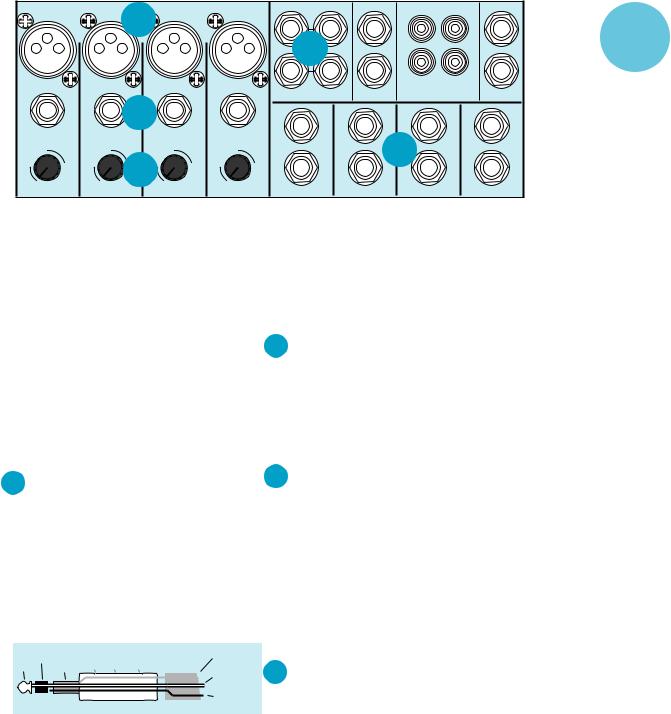
2 Ch. 1–4 Line Inputs
Line inputs 1–4 are a good place to connect older keyboards which have low gain, or keyboards in general since you can adjust the corresponding channel TRIM control so that the mixer has plenty of gain but you can keep the keyboard volume control set around the halfway mark.
3 Trim controls
TRIM 1 through 4 adjusts the input sensitivity of the mic and line inputs connected to Channels 1 through 4. This allows signals from the proverbial outside world to be brought in at optimal internal operating levels. See Level Setting instructions on page 12.
4 Chs. 5–6, 7–8, 9–10, 11–12 Line Inputs
These four line inputs share circuitry (but not phantom power) with the mic preamps, and can be driven by balanced or unbalanced devices at almost any level. In other words, you can use these inputs for virtually any signal you’ll come across, from instrument levels to levels of –10 to +4, since there is 40dB more gain available than on Channels 5–12.
|
ring |
|
|
shield |
|
tip |
sleeve |
cuff |
hem garter belt |
(ground) |
|
positive |
|||||
|
|
|
|
||
|
|
|
|
(white wire) |
|
|
|
|
|
negative |
|
|
|
|
|
(black wire) |
To connect these inputs to balanced sources, use a Tip-Ring-Sleeve (TRS) or three-conductor plug (the type found on stereo headphones):
Tip |
= Positive (+ or hot) |
Ring |
= Negative (– or cold) |
Sleeve |
= Shield or ground |
To connect the inputs to unbalanced sources, use a mono phone plug or standard instrument cable. The jack on the MS 1202 will sense the plug and disable the balancing circuits.
These inputs are designed for stereo or mono unbalanced signals from –10dBV to +4dBu. They can be used with just about any professional or semi-pro instrument, effect, or tape player. In the audio world, an oddnumbered channel usually receives the “left signal”. For example, feed line inputs 5–6 a stereo signal by inserting the device’s left output plug into the Channel 5 jack, and its right output plug into the Channel 6 jack.
5 STEREO AUX RETURNS to Master
This is where you connect the outputs of your effects devices. The STEREO AUX RETURNS are wired identically to the stereo line inputs. The circuits will handle stereo or mono unbalanced signals, either instrument level, –10dBV or +4dBu. They can be used with just about any pro or semi-pro effect on the market.
Additional information on connecting effects to the MS 1202 starts on page 11.
5
 Loading...