


 Loading...
ProFire 610
English
User Guide
ProFire 610 |
User Guide |
1 |
Introduction . |
3 |
2 |
What’s in the Box. |
3 |
|
Your ProFire 610 package contains . |
3 |
3 |
ProFire 610 Features . |
4 |
4 |
Minimum System Requirements |
4 |
5 |
Controls and Connectors. |
5 |
|
Front Panel Descriptions. |
5 |
|
Rear Panel Descriptions. |
7 |
6 |
Driver Installation . |
8 |
7 |
Hardware Connections. |
8 |
|
Connecting Microphones and/or Instruments. |
9 |
|
Connecting Line-Level Inputs . |
9 |
|
Digital (S/PDIF) Connections. |
9 |
|
Headphone Monitoring. |
9 |
|
Connecting the Analog Outputs . |
10 |
8 |
Software Control Panel . |
11 |
|
Mixer Tabs. |
11 |
|
Level Meter. |
12 |
|
Pan. |
12 |
|
Mute . |
12 |
|
Solo . |
12 |
|
Stereo Link . |
13 |
|
Level Fader. |
13 |
|
Channel Name. |
13 |
|
Settings Tab. |
13 |
|
Hosted Mode – Sync Source . |
14 |
|
Hosted Mode – Sample Rate . |
14 |
|
Hosted Mode – ASIO / WDM Buffer Size . |
14 |
|
Standalone Mode – Sync Source. |
14 |
|
Standalone Mode – Sample Rate. |
15 |
|
Mixers Active at Sample Rates Above 96 kHz . |
15 |
|
Master Volume Knob. |
15 |
ProFire 610 |
User Guide |
About Tab. |
16 |
Additional Functions. |
16 |
File. |
16 |
Edit. |
17 |
View. |
17 |
Help. |
18 |
9 Using ProFire 610. |
19 |
Setting Input Levels . |
19 |
Mic/Inst Inputs . |
19 |
Line Inputs. |
19 |
S/PDIF inputs . |
19 |
Configuring your Audio Software. |
20 |
Selecting ProFire 610 as the audio device. |
20 |
Routing your software outputs . |
20 |
Setting the sample rate and bit depth of your session . |
20 |
About Overdub Recording and Monitor Mixing . |
21 |
Using the Monitor Mixer. |
22 |
10 Standalone Operation. |
24 |
11 Digital Clocking. |
25 |
Scenario 1: ProFire 610 as Clock Master . |
26 |
Scenario 2: ProFire 610 Slaved to S/PDIF Input. |
27 |
Scenario 3: Creating a Synchronized “Digital Loop”. . . . . . . . . . . . . . . . . . . . . . . . . . . . . . . . . . . . . . . . . . 28 |
|
12 MIDI. |
29 |
13 Troubleshooting. |
30 |
14 Warranty. |
32 |

ProFire 610 |
User Guide |
3 |
1 Introduction
Congratulations on your purchase of the M-Audio ProFire 610 audio interface. ProFire 610 is part of M-Audio’s award winning series of FireWire1-based digital recording systems and features solid hardware design, robust driver technology, and a powerful Control Panel application to help you capture your best performances with the highest possible fidelity.
This rugged interface includes many features found on the flagship ProFire 2626 interface including a powerful DSP-based monitor mixer, high quality preamplifiers featuring Octane™ technology, two discrete headphone outputs, and an assignable Master Volume Control knob to facilitate many
kinds of recording and mixing. Furthermore, the portable design and bus powered operation of ProFire 610 allow you to make professional-grade recordings anywhere—at the studio or on the road.
Even if you’re an experienced digital recording enthusiast, please take a moment to read through this User Guide and familiarize yourself with the features and operation of ProFire 610. You may also want to refer to your audio software’s documentation to better understand how ProFire 610’s features are integrated with the program. Your experience and enjoyment of your ProFire 610 will be greatly enhanced by a good working knowledge of your audio software.
NOTE: Do not connect or disconnect bus-powered M-Audio, or 3rd party FireWire devices while your computer is running (i.e. no “hot-plugging”). Make all FireWire cable connections while the computer is powered off. See page 7 for more information about this topic.
2 What’s in the Box
Your ProFire 610 package contains:
•ProFire 610 interface
•Printed Quick Start Guide
•6-pin to 6-pin FireWire cable
•6-pin to 4-pin FireWire cable
•FireWire Series CD-ROM containing drivers and documentation
•Software Bundle CD-ROM
•12VDC 2A Power Supply

ProFire 610 |
User Guide 4 |
||
3 |
|
|
|
ProFire 610 Features |
|
|
|
•Six-input, ten-output audio configuration
•Up to 24-bit/192kHz operation
•Two high-quality mic/instrument preamps featuring OctaneTM technology, LED meters, and phantom power
•Two front-panel XLR/TS Combo jacks accepting mic or instrument level inputs
•Two rear-panel 1/4” TRS balanced line inputs
•Eight rear-panel 1/4” TRS balanced line outputs
•Two independent 1/4” headphone outputs with volume control knobs for each output
•S/PDIF In/Out
•MIDI In/Out
•Powerful onboard DSP providing five near-zero latency 16x2 monitor mixers
•User-assignable Master Volume control
•Functions as a standalone two-channel mic preamp and A/D – D/A converter
4 Minimum System Requirements
Minimum system requirements can be found on the ProFire 610 product packaging as well as the M-Audio website.
A Note about Operating System Updates: Please check the M-Audio driver download page at http://www.m-audio.com/drivers for the availability of an updated driver before you decide to install operating system updates.
Before new M-Audio device drivers are released, they are tested for use with the operating system versions that are available at that time. When updates for an operating system are released by Microsoft or Apple, all M-Audio device drivers have to be re-tested and possibly updated to ensure proper operation.
M-Audio recommends refraining from installing operating system updates until a driver has been posted to the M-Audio website for that specific operating system.
ProFire 610 |
User Guide |
5 |
5 Controls and Connectors |
|
|
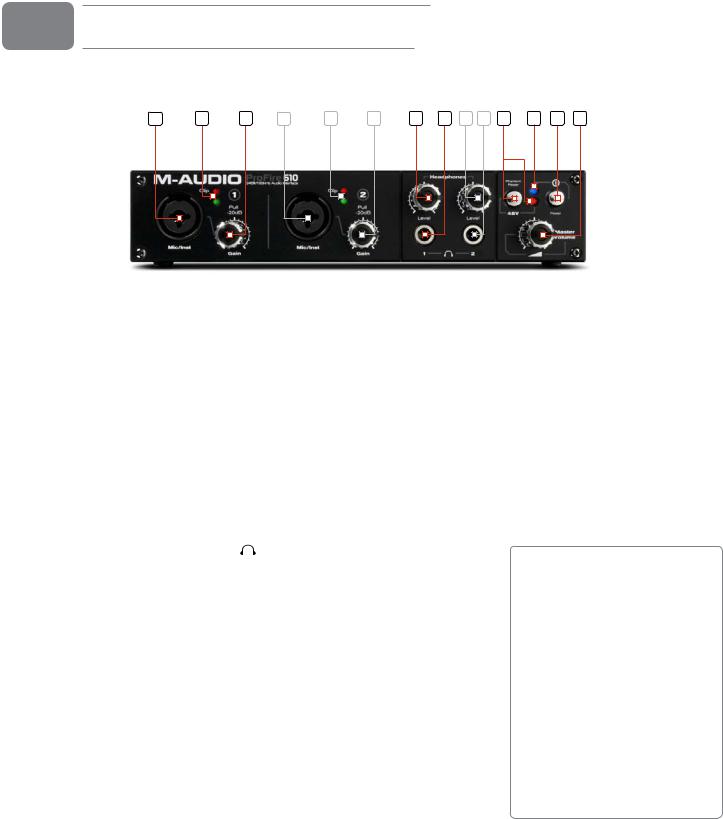
Front Panel Descriptions |
|
|
|
|
|
1.Mic / Inst Input Combo Jack (Mic / Inst) - Balanced mic-level and unbalanced instrument-level combo inputs.
These combo connectors will accept a standard three-pin XLR plug or a 1/4” TS connector and will appear as the first pair of inputs (e.g. inputs 1/2) in your audio application. Input levels are controlled by the corresponding Gain knobs.
2.Signal/Clip Indicators (Clip) - The green LED indicates the presence of a signal at the corresponding analog input while the red LED indicates “clipping” or distortion at the input. Use these LED meters to set levels for the first two analog inputs.
3.Gain Knob (Gain) - The preamp level for the front panel inputs is adjusted with this knob. It also has a push/pull function which engages a 20dB pad when set to the “out” (pulled) position.
4.Headphone Volume Knobs (Level) - Each of these two knobs controls the volume level of the associated headphone output jack.
5.Headphone Outputs (


 ) - These two 1/4” (TRS)
headphone output jacks operate independently from each other. The first headphone jack outputs the same audio signal as rear-panel outputs 1/2 while the second headphone jack outputs the same audio signal as rear-panel outputs 3/4.
6.Phantom Power Button and LED (48V) - This button applies +48V phantom power to the XLR inputs on the front of the interface. The LED next to the button illuminates when phantom power is being sent to the XLR inputs.
7.Power LED Indicator - The blue Power LED glows steadily when the device is receiving power via the FireWire bus or the external power supply. The LED will blink off and on if the unit is set to external sync and not receiving a valid clock signal.
8.Power Button (  ) - This button switches the interface on and off.
About Phantom Power:
Be mindful when engaging phantom power since not all microphones require phantom power to operate. For example, most dynamic microphones do not require any phantom power whereas condenser microphones usually do. Some vintage ribbon microphones may be damaged if phantom power is applied
to them. Always consult your microphone’s manual before applying phantom power.

ProFire 610 |
User Guide |
6 |
9.Master Volume ( ) - This knob controls the analog output levels of ProFire 610. Turning the knob clockwise will increase the output level while turning it counterclockwise will reduce the output level.
By default, this knob is assigned to control analog outputs 1/2, however, the Control Panel application provides the option of setting the Master Volume knob to control any combination of analog output pairs (i.e., 1/2, 3/4, 5/6, or 7/8). This includes the ability to control the level of all eight analog outputs simultaneously. This feature has been implemented to facilitate many kinds of stereo and surround mixing scenarios.
See the Control Panel section of this User Guide for more information about how to configure and use the Master Volume knob.
NOTE: If this knob is assigned to control analog output pairs 1/2 or 3/4, it will also affect the level of the first and second headphone outputs, respectively. The section “Connecting the Analog Outputs” includes a tip on how to configure the interface to give you three separate volume control knobs (i.e., one knob for each headphone output and the Master Volume knob to control your speakers). See page 10 of this guide for more information about this topic.
!WARNING: Unchecking one of the Master Volume Knob boxes allows its corresponding outputs to play at full volume (i.e., without any attenuation). This may result in very loud signals being sent to your speakers, headphone amplifiers, or other equipment. Be mindful of your outgoing levels anytime you uncheck one of these boxes to avoid potentially damaging your equipment (or hearing). If you wish to leave these boxes unchecked in order to allow full, unattenuated signals to play through the interface, it is strongly recommended that you have an external provision for controlling your levels (such as a an external mixer).
ProFire 610 |
|
|
|
User Guide |
7 |
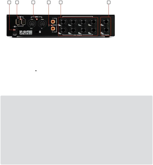
Rear Panel Descriptions |
|
|
|||
|
|
|
|
|
|
10.Power Input ( 
 ) - Connect the 12VDC 2A power supply here when using ProFire 610 with a four-pin FireWire connection, or if your computer does not provide sufficient bus power on a 6-pin connection. If your computer can provide power over a 6-pin connection, it is not necessary to use the included power supply.
Use only the power supply provided with the interface or a power supply with equivalent specifications.
11.FireWire Connectors (
 ) - Connect your computer to ProFire 610 using one of these FireWire ports and the included FireWire cable. The second FireWire port allows additional equipment, such as an external hard drive, to be connected in a daisy-chain to the computer. Do not connect the second FireWire port to another computer. ProFire 610 does not offer any kind of FireWire networking capabilities and attaching the interface to two computers may result in damage to the interface and/or the computers.
!IMPORTANT: Do not connect or disconnect bus-powered M-Audio, or 3rd party FireWire devices while your computer is running (i.e. no “hot-plugging”). Make all FireWire cable connections while the computer is powered off.
Reports have come to our attention of isolated problems when hot-plugging IEEE 1394 (aka “FireWire”) devices, including, but not limited to devices of the M-Audio FireWire family.
Hot-plugging refers to making connections to1394/FireWire ports while one or more of the devices (including the computer) are still powered on. There have been rare occurrences when, after hot-plugging, either the FireWire peripheral or the host computer’s FireWire port are rendered permanently inoperable.
Please consult the Knowledge Base in the Support section at www.m-audio.com for updates on this important issue.
12.MIDI In and MIDI Out Connectors - MIDI input and output on standard 5-pin DIN connectors. Connect a MIDI controller keyboard, sound module or other MIDI device to these ports.
13.S/PDIF Coaxial In and Out Connectors - S/PDIF digital input and output on coaxial RCA connectors. Sample rates of up to 192kHz are supported.
14.Line Outputs - These 1/4” TRS jacks provide eight channels of discrete balanced or unbalanced analog output.
15.Line Inputs - These two 1/4” TRS jacks provide two channels of balanced or unbalanced analog input. These will appear as the second pair of inputs (e.g. inputs 3/4) in your audio application.

ProFire 610 |
User Guide |
8 |
||
6 |
|
|
|
|
Driver Installation |
|
|
|
|
For instructions on installing ProFire 610, please refer to the printed Quick Start Guide.
7 Hardware Connections
#ABLE8,2 |
#ABLEv |
-IC 'UITAR "ASS (EADPHONES
ProFire 610 front
|
%XTERNAL |
|
-)$))+EYBOARD |
|
#OMPUTER |
(ARD $RIVE |
|
|
-ONITORS T-IXER |
|
|
|
%FFECTSE0ROCESSOR0 |
|
&IRE7IRE |
&IRE7IRE |
IN |
3 0$)& |
$!4 |
|
||||
)$) |
|
$!4 |
||
- |
|
|||
|
|
|
|
|
0OWER |
|
|
|
|
3UPPLY |
|
|
|
|
|
-)$)OUT |
|
|
|
|
|
|
|
3OUNDU-ODULE |
ProFire 610 rear

ProFire 610 |
User Guide |
9 |
Connecting Microphones and/or Instruments |
|
|
ProFire 610 features two XLR/TS Combo input jacks 1 |
on its front panel. Microphones or instrument-level |
|
sources (electric guitars, basses, etc.) can be connected to these inputs using XLR or 1/4” cables, respectively.
If you are using microphone(s) that require phantom power, activate the Phantom Power button 9 after the microphone(s) have been connected.
NOTE: Phantom power is only applied to the XLR portion of the front panel combo connectors and does not affect 1/4” instrument inputs in any way. Instruments can be connected to the combo inputs regardless of the status of the phantom power switch.
Connecting Line-Level Inputs
ProFire 610 can simultaneously record audio from up to two line-level sources. Connect your line level devices to the rear-panel Line Inputs 15 .
Digital (S/PDIF) Connections
ProFire 610 features coaxial (RCA) S/PDIF input and output connectors on its rear panel. These jacks can be used to send and receive digital data from any device that has coaxial S/PDIF inputs or outputs.
NOTE: Whenever audio devices are digitally interconnected through S/PDIF, you must set up proper digital synchronization among all of the devices to ensure error free transfer of audio. The “Digital Clocking” section of this guide covers this topic in detail.
Headphone Monitoring
ProFire 610 features two headphone outputs on its front panel. The first headphone jack outputs the same audio signal as rear-panel outputs 1/2 while the second headphone jack outputs the same audio signal as rear-panel outputs 3/4.
The first two tabs of the Control Panel (e.g., the “Analog Out 1/2” and “Analog Out 3/4” tabs) are used to set up mixes for these outputs, respectively. Headphone monitoring and mixing is covered in greater detail in the “About Overdub Recording and Monitor Mixing” section of this guide.
NOTE: If the Master Volume knob 9 is assigned to control analog output pairs 1/2 or 3/4, it will also affect the level of the first and second headphone outputs, respectively.
ProFire 610 |
User Guide |
10 |
Connecting the Analog Outputs
Connect the rear-panel line outputs 13 to a mixing console, amplifier or powered monitors. By default, analog output pair 1/2 is controlled by the front-panel Master Volume knob 6 , however, this knob can be assigned to control other outputs pairs through the ProFire 610 Control Panel.
!CAUTION: Analog output streams that are not assigned to be controlled by the Master Volume knob will be sent to the analog outputs at maximum level.
TIP: To control the level of the main monitor mix without affecting the level at the headphone outputs, assign the Master Volume knob to either analog outputs 5/6 or 7/8 and use those outputs for your main monitors. This prevents the Master Volume Knob from influencing the levels of headphone outputs 1 and 2 and effectively provides front panel volume controls for three unique stereo outputs.
If you already have a way of controlling the main monitor mix level (e.g. through the use of an external mixer), another good use for the assignable Master Volume Knob is as an auxiliary send. Simply connect one of the analog output pairs to an outboard effects unit and assign the Master Volume Knob to the respective channels. Bring the outboard effect’s outputs back into the ProFire 610 interface using line inputs 3 and 4 as the auxiliary return and use the Master Volume Knob to control the auxiliary send level.
Loading...