


 Loading...
10 in 10 out PCI Digital Recording System with S/PDIF
User Guide

Table of Contents
Introduction . . . . . . . . . . . . . . . . . . . . . . . . . . . . . . 3 What’s in the Box? . . . . . . . . . . . . . . . . . . . . . . . . . . 3
About the Delta 1010 Digital Recording System . . . |
. . . . . . . . 4 |
|||||
Product Features & Specifications . . . . . . . . . . . . . . . . . . 5 |
||||||
Minimum System Requirements . . . . . . . . . . . . . . . . . . . 6 |
||||||
Hardware Controls and Indicators . . . . . . . . . . . . . . . . . . 6 |
||||||
Rack Unit Front Panel . . . . . . . . . . . . . . . . . . |
. |
. . . . |
. |
. |
. |
6 |
Rack Unit Back Panel. . . . . . . . . . . . . . . . . . . |
. |
. . . . |
. |
. |
. |
7 |
PCI Host Adapter Card . . . . . . . . . . . . . . . . . . |
. . . . . . . . 8 |
|||||
Delta System Overview . . . . . . . . . . . . . . . . . . . . . . . . 10 |
||||||
Analog Inputs/Outputs . . . . . . . . . . . . . . . . . . |
. |
. . . . |
. |
. |
. 10 |
|
The Digital Monitor Mixer . . . . . . . . . . . . . . . . . |
. . . . . . . . 10 |
|||||
The Patchbay / Router . . . . . . . . . . . . . . . . . . . . . . . . . . 11 |
||||||
Synchronization . . . . . . . . . . . . . . . . . . . . . . . . . . . . . 11 |
||||||
Using Delta 1010 with your Audio Software . . . . . |
. |
. . . . |
. |
. |
. 12 |
|
Audio Inputs . . . . . . . . . . . . . . . . . . . . . . |
. |
. . . . |
. |
. |
. 12 |
|
Audio Outputs . . . . . . . . . . . . . . . . . . . . . |
. . . . . . . . 13 |
|||||
Control Panel Software . . . . . . . . . . . . . . . . . . . . . . . 14 |
||||||
Delta Control Panel for Windows XP . . . . . . . . . . . . . |
. |
. . . . |
. |
. |
. 14 |
|
Monitor Mixer Tab . . . . . . . . . . . . . . . . . . . |
. |
. . . . |
. |
. |
. 14 |
|
Patchbay/Router Tab . . . . . . . . . . . . . . . . . . |
. |
. . . . |
. |
. |
. |
17 |
Hardware Settings Tab . . . . . . . . . . . . . . . . . |
. |
. . . . |
. |
. |
. 18 |
|
S/PDIF Tab . . . . . . . . . . . . . . . . . . . . . |
. |
. . . . |
. |
. |
. 22 |
|
Bass Management Tab . . . . . . . . . . . . . . . . . |
. |
. . . . |
. |
. |
. 25 |
|
About Tab . . . . . . . . . . . . . . . . . . . . . |
. |
. . . . |
. |
. |
. 26 |
|
Additional Control Panel Features. . . . . . . . . . . . . . |
. |
. . . . |
. |
. |
. 26 |
|
Control Panel Software for Mac OS X . . . . . . . . |
. |
. . . . |
. |
. |
. 27 |
|
Monitor Mixer Tab . . . . . . . . . . . . . . . . . . . . |
. |
. . . . |
. |
. |
. 27 |
|
Patch Bay Tab . . . . . . . . . . . . . . . . . . . . . |
. |
. . . . |
. |
. |
. 30 |
|
Hardware Settings Tab . . . . . . . . . . . . . . . . . . |
. |
. . . . |
. |
. |
. 31 |
|
S/PDIF Tab . . . . . . . . . . . . . . . . . . . . . . |
. |
. . . . |
. |
. |
. 33 |
|
About Tab . . . . . . . . . . . . . . . . . . . . . . . |
. |
. . . . |
. |
. |
. 36 |
|
Additional Control Panel Features . . . . . . . . . . . . . . |
. |
. . . . |
. |
. |
. 36 |
|
Troubleshooting. . . . . . . . . . . . . . . . . . . . . . . . . . . . 38 Technical Specifications . . . . . . . . . . . . . . . . . . . . . . . 41 Technical Info . . . . . . . . . . . . . . . . . . . . . . . . . . . . . 42 Appendix . . . . . . . . . . . . . . . . . . . . . . . . . . . . . . . 43
Appendix A: Clocking . . . . . . . . |
. |
. . . . . . . . |
. |
. |
. . . |
. |
. |
. |
. 43 |
Warranty Terms and Registration |
. |
. . . . . . . . |
. |
. |
. . . |
. |
. |
. |
. 44 |

Delta 1010 User Guide |
| 3 |
Introduction
1
Congratulations on your purchase of the Delta 1010 audio interface. Delta 1010 is the top product in M-Audio’s line of award winning “Delta” digital recording
systems and has helped set the standard for the solid hardware design and robust driver technology found in other members of the Delta family.
Even if you are experienced with digital recording, please take a moment to read through this manual. It will give you valuable information about the Delta 1010 interface and will help you get the most out of your new purchase. You may also want to refer to your audio software’s documentation to better understand how Delta 1010 can be integrated with the application. Your experience and enjoyment with the interface will be greatly enhanced by a good working knowledge of your equipment.
What’s in the Box?
2
Your Delta 1010 package contains:
<Delta 1010 rack-mount interface
<PCI Host Adapter card
<Host connector cable
<9V AC 3A in-line power supply unit
<Printed Quick Start Guide
<Delta Series CD-ROM containing drivers, Control Panel software, and documentation

4 | |
Delta 1010 User Guide |
About the Delta 1010 Digital Recording System
3
Delta 1010 is a professional audio interface with a total of 10 inputs and 10 outputs. The interface features eight 1/4” balanced/unbalanced analog inputs
and outputs as well as a pair of coaxial (RCA) S/PDIF I/O. Delta 1010 can create pristine 24-bit recordings at sampling rates of up to 96 kHz.
Connect line-level audio sources (i.e., keyboards, mixers, preamplifiers, etc.) to the 1/4” input jacks on the rear of the interface. Set the operating line level for each input using the +4/-10 switch located next to each jack. Connect your DAT recorder, MiniDisc player, or other digital device to Delta 1010’s S/PDIF ports on the PCI Host card. Control all routing and hardware settings using the Control Panel software.
The sturdy 1U rack-mount chassis houses all of the A/D and D/A converters, keeping them away from the electrically noisy environment inside your computer and assuring the best audio performance. The rack unit features Word Clock I/O connectors, which allow you to synchronize Delta 1010 with all of your other Word Clock capable devices. Also, the interface features MIDI input and output ports, allowing you to connect MIDIcapable devices (synthesizers, drum machines, etc.) to your computer or to synchronize external devices with your interface using a sync protocol such as MIDI Time Code (MTC).
Finally, the Delta 1010 PCI Host Adapter card features a flexible digital mixer. This mixer handles routing within the interface and gives you control over volume, pan, solo, and mute just like on a hardware mixer used for monitoring.

Delta 1010 User Guide |
| 5 |
Product Features & Specifications
4
<10-input, 10-output recording interface
<Supports up to 24-bit, 96kHz operation
<PCI host card with DSP for digital mixing
<Sturdy rack-mounted I/O interface
<Eight balanced/unbalanced analog inputs and outputs on 1/4” connectors with +4dB or -10dB operation (operating levels are individually selectable for each channel)
<MIDI, Word Clock, and S/PDIF inputs and outputs
<Balanced or unbalanced operation
<High dynamic range: D/A 114dB, A/D 109dB (A-weighted)
<Low distortion (measured THD @ 0dBFS): A/D 0.001%, D/A 0.0015%.
<All data paths support up to 24bit/96kHz performance.
<Control Panel software for mixing, routing, and monitoring capabilities
<Sample-accurate hardware sync allows linking of up to four Delta 1010 interfaces in one computer
<Windows XP drivers for ASIO/ASIO2, WDM, DirectX, MME, and GSIF/GSIF2 protocols.
<Mac OS X drivers for Core Audio and Core MIDI
6 | |
Delta 1010 User Guide |
Minimum System Requirements*
5
Windows*
<Windows XP** Service Pack 2
<Pentium III 933MHz
<256 MB RAM
Mac*
<G3† processor using Mac OS X 10.3.9 with 256 MB RAM
<G4† processor using Mac OS X 10.3.9 / 10.4.8 or higher with 512 MB RAM
*M-Audio suggests that you also check the minimum system requirements for your software, as they may be greater than Delta 1010’s requirements.
**Home and Professional Edition only. Windows Media Center Edition is not currently supported
†G3/G4 accelerator cards not supported.
Hardware Controls and Indicators
6
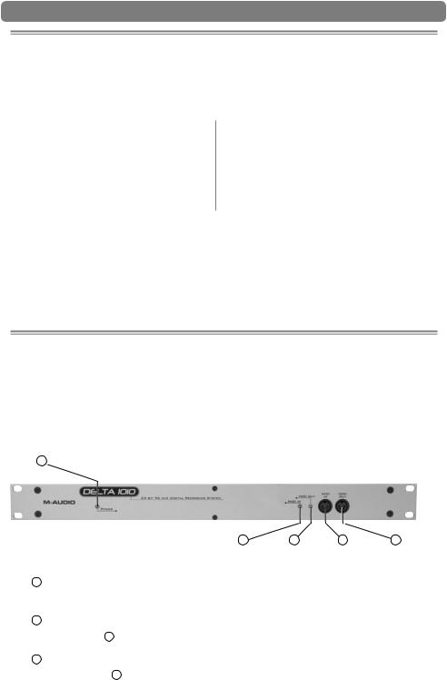
Rack Unit Front Panel:
|
|
|
|
1Power Indicator LED (Power): This LED illuminates when the interface is powered on and has established communication with your host computer.
2MIDI Input LED: This LED illuminates when MIDI data is received at the MIDI Input Jack 4 .
3MIDI Output LED: This LED illuminates when MIDI data is sent from the MIDI Output jack 5 .
Delta 1010 User Guide |
| 7 |
4MIDI Input Jack (MIDI In): This standard 5-pin MIDI connector accepts signals from any MIDI compatible device such as a keyboard or control surface.
5MIDI Output Jack (MIDI Out): This standard 5-pin MIDI connector transmits signals to any MIDI compatible device such as a synthesizer, sound module, or drum machine.
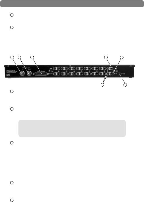
Rack Unit Back Panel:
|
|
|
|
|
6Word Clock In (WORDCLOCK In): Delta 1010 is capable of synchronizing its sample rate clock with that of an incoming word clock signal using this BNC input.
7Word Clock Out (WORDCLOCK Out): This BNC output transmits a Word Clock signal that is in sync with the present sample rate clock of Delta 1010.
The Word Clock input and outputs (6, 7) are designed to work with 75-ohm coaxial BNC cables. Be sure to use 75-ohm BNC cables to ensure good performance.
8Host Cable Connector (HOST CABLE): Use the supplied 25-pin host cable to connect this jack to the Delta 1010 PCI Host Adapter card.
IMPORTANT: Do not connect the PCI Host Adapter card and rack-mount portion of the interface when your computer is powered on. Doing so may damage the rack-mount interface and/or the PCI card. Only connect (or disconnect) the PCI card and rack-mount unit when your computer is powered off.
9Analog Inputs 1-8 (INS): These eight 1/4” jacks accept line-level signals from any balanced (TRS) or unbalanced (TS) device. The sensitivity of each input can be configured using the +4/-10 switch (11) to the left of each input.
10Analog Outputs 1-8 (OUTS): These eight 1/4” jacks output balanced, linelevel signals for monitoring, mixing, or processing with external devices. The sensitivity of these outputs can be configured using the +4/-10 switch (11) to the left of each output. Note that these balanced outputs are fully compatible with unbalanced devices as well.
8 | |
Delta 1010 User Guide |
11Signal-Level +4/-10 Switch: This button sets the operating signal level for each analog input and output channel. When this switch is in the out position, its associated channel will operate at the professional +4dBu standard; when the switch is pressed, the channel will operate at -10dBV.
About the +4/10 button: The +4dBu standard is used by most mixers, preamplifiers, and other professional audio devices with balanced outputs. Devices with unbalanced outputs commonly use the -10dBV standard. If you’re not sure about the operating level of a device you’ve connected to your Delta 1010, refer to the device’s user manual.
12 Power Jack (9V AC): Connect the supplied 9V AC power supply to this jack.
IMPORTANT: Do NOT connect a DC power supply to this jack. Doing so may damage the interface. Delta 1010 requires a 9V AC supply, with at least 3 ampere capability.
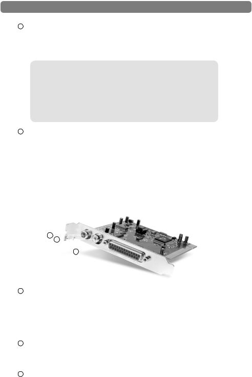
PCI Host Adapter Card:

13Coaxial S/PDIF Input: This RCA connector allows Delta 1010 to receive a stereo S/PDIF signal from any device with a coaxial (RCA) S/PDIF digital output such as a DAT machine, MiniDisc player, or external A/D converter.
NOTE: The S/PDIF Input is only available when Delta 1010’s Master Clock source is set to “S/PDIF” or “Word Clock.”
14Coaxial S/PDIF Output: This RCA connector lets you send a stereo S/PDIF signal to any device that can receive a coaxial (RCA) S/PDIF signal such as a DAT recorder, MiniDisc recorder, or external D/A converter.
15Host Cable connector: Use the supplied Host Cable to connect this jack to the Host Cable Connector (8) on the rack-mount portion of the Delta 1010 interface.

Delta 1010 User Guide |
| 9 |
IMPORTANT: Do not connect the PCI Host Adapter card to the rack-mount chassis when your computer is powered on. Doing so may damage the interface. Only connect (or disconnect) the PCI card and rack-mount unit when your computer is powered off.
IMPORTANT: The Host Cable connector features a 25-pin jack that looks like the parallel (printer) port connection found on some computers. If your computer has a parallel port, be careful not to confuse these two connectors and do not attempt to connect the PCI Host Adapter card to anything other than the rack-mount portion of the Delta 1010 interface. Doing so may damage the interface.
The PCI Host Adapter card and rack-mount portion of the interface are connected using a standard 25-pin “D-Sub” cable. This is the same type of “bidirectional printer cable” used to connect printers to the parallel port (printer port) of a computer. This type of cable is commonly available through computer and professional audio stores and M-Audio has successfully tested Delta 1010 with cables up to 25 feet in length. If the supplied Host Cable is not long enough for optimal for computer/ interface placement, consider replacing the included cable with a longer one.

10 | |
Delta 1010 User Guide |
Delta System Overview
7
Analog Inputs/Outputs
Delta 1010’s analog inputs and outputs allow you to record a variety of audio sources and to playback your recordings to many destinations. On the rear of the interface, you will find eight 1/4” inputs and eight 1⁄4” outputs with independent +4/-10 signal level buttons (11) next to each jack. Be sure to set these switches properly to ensure the best possible sound quality.
All of the analog inputs and outputs on the rear of the Delta 1010 are balanced 1/4” jacks. These jacks allow connection to either balanced (TRS) or unbalanced (TS) linelevel devices.
NOTE: Since Delta 1010 does not have microphone pre-amplifiers built into the inputs, it is not possible to use a microphone that is connected directly to the interface. To record a microphone, you must first pass the microphone signal through a microphone preamplifier (such as the M-Audio TAMPA) and connect the preamplified line-level or S/PDIF output to the input of the Delta 1010.
The Digital Monitor Mixer
Delta 1010 features a hardware digital audio mixer built into its PCI Host Adapter card. This mixer accepts digital audio from all hardware inputs and all software audio outputs, mixes them with 36-bit internal precision, and then provides the mixed signal to analog outputs 1-2 and/or the S/PDIF outputs for monitoring purposes. While the mixer is primarily intended to be used for creating monitor mixes, it may also be used for stereo mixing since its output can be recorded back into your audio application. The digital audio mixer is configured and controlled by the included Control Panel software.
Delta 1010 User Guide |
| 11 |
The Patchbay / Router
In addition to the built-in Monitor Mixer, Delta 1010 also provides virtual signal patching and routing capabilities. This “Patchbay/Router” is accessed through the Control Panel software and allows a variety of sources (including your music software, the analog and digital inputs of the interface, or the Monitor Mixer output) to be linked to various physical outputs on the interface. This flexible routing capability allows you to use Delta 1010 in a variety of different situations and to quickly reconfigure the interface without having to physically disconnect and reconnect the hardware inputs and outputs on the rear of the interface.
Synchronization
For proper operation, all digitally interconnected audio systems (including the Delta 1010 interface) must be synchronized to a single master clock. If your digital audio systems are not configured in this way, you are likely to hear clicks, pops, and other glitches in your audio streams. The Control Panel software allows you to synchronize the interface to its internal clock or to “lock” to an external clock source being received at the S/PDIF or Word Clock inputs. This allows you to easily install the Delta 1010 hardware into any kind of digital environment where S/PDIF or Word Clock are being used.

12 | |
Delta 1010 User Guide |
Using Delta 1010 with your Audio Software
8
After Delta 1010’s hardware and drivers have been installed, you may need to select or enable the interface in your audio software before you can begin
recording. This process is usually done through a “setup” or “audio preferences” menu within the program. Refer to your software’s documentation to learn how to do this.
Audio Inputs:
Once your audio software is configured, you may begin recording with the interface. The following list should help you associate the input names displayed by your audio software with Delta 1010’s corresponding physical inputs:
Display Name |
Corresponding Inputs |
|
|
|
|
Delta 1010 1/2 |
Analog Inputs 1/2 |
|
Delta 1010 |
3/4 |
Analog Inputs 3/4 |
Delta 1010 |
5/6 |
Analog Inputs 5/6 |
Delta 1010 |
7/8 |
Analog Inputs 7/8 |
Delta 1010 |
9/10 |
S/PDIF Input |
*Delta 1010 11/12 |
*Summed Monitor Mixer Signal |
|
|
|
|
NOTE: There may be slight variations in the naming of inputs when using certain audio applications. For example, an input pair may be labeled “ASIO 1-2” instead of “Delta 1010 1/2.” Furthermore, some programs may break down the inputs listed above into individual “left” and “right” mono channels. In this case, the software may display the inputs as “Left Delta 1010 1,” “Right Delta 1010 2,” etc. Refer to your application’s user guide to learn more about how inputs are labeled.
“Delta 1010 1/2” through “Delta 1010 7/8” correspond to analog inputs 1-8 on the rear of the rack-mount interface.
“Delta 1010 9/10” corresponds to the red S/PDIF input on the PCI Host Adapter card.
NOTE: The S/PDIF Input will not accept incoming signals if Delta 1010’s Clock Source is set to “Internal Xtal” in the Control Panel. To ensure proper operation, set the Clock Source to S/PDIF and make sure that the connected source device is configured as clock master. Please see the Digital Synchronization and Multi-Device Setup Guide found at http://www.m-audio.com for more information.
*“Delta 1010 11/12” is the output of the hardware Monitor Mixer on the PCI card and can be selected if you wish to record the combined physical and virtual inputs (audio returning from your recording software) of the Monitor Mixer.

Delta 1010 User Guide |
| 13 |
Audio Outputs:
The following list should help you associate the output names displayed by your software with Delta 1010’s corresponding physical outputs:
Display Name |
Corresponding Outputs |
|
|
|
|
Delta 1010 1/2 |
Analog Outputs 1/2 |
|
Delta 1010 |
3/4 |
Analog Outputs 3/4 |
Delta 1010 |
5/6 |
Analog Outputs 5/6 |
Delta 1010 |
7/8 |
Analog Outputs 7/8 |
Delta 1010 |
9/10 |
S/PDIF Output |
|
|
|
NOTE: There may be slight variations in the naming of outputs when using certain audio applications. For example, an output pair may be labeled “ASIO 1-2” instead of “Delta 1010 1/2.” Furthermore, some programs may break down the outputs listed above into individual “left” and “right” mono channels. In this case, the software may display the outputs as “Left Delta 1010 1,” “Right Delta 1010 2,” etc. Refer to your application’s user guide to learn more about how outputs are labeled.
When using the Patchbay/Router’s default settings, signals from your audio application will be sent directly to Delta 1010’s corresponding physical outputs. Keep in mind that the Patchbay/Router allows you to modify the output routing of the interface. In other words, if the Patchbay/Router default settings have been altered, selecting an output port by name in your audio software may not send audio to the corresponding hardware output. To learn more about the Patchbay/Router, see the “Patchbay/Router Tab” section in the Control Panel chapter of this guide.
NOTE: Some audio applications may make certain Control Panel settings unavailable while the application is open. If your software does this, close the audio application before changing your Control Panel setting. Alternatively, certain DAW applications allow you to launch the Control Panel or change Control Panel settings from within the application itself. This process varies from program to program, but it is usually done through the “configuration” or “audio setup” page of your software.
14 | |
Delta 1010 User Guide |
Control Panel Software
9
Delta 1010 is a powerful audio interface with a variety of options and parameters relating to its operation. After installing the Delta 1010 drivers, you can use the Control Panel software to configure the various parameters of the interface. Since the appearance and functionality of the Control Panel varies slightly between Windows XP
and Mac OS X, each operating system is covered separately in this guide.
Delta Control Panel for Windows XP
This section covers the Control Panel for Windows XP users. Mac OS X users should skip to the following section of this User Guide to learn about the Mac OS X Control Panel.
To access the Delta Control Panel in Windows, double-click the M-Audio icon in the system tray, or click Start > Control Panel and double-click the Delta 1010 Control Panel icon. Your audio software may also allow you to access the Control Panel from within the application itself.
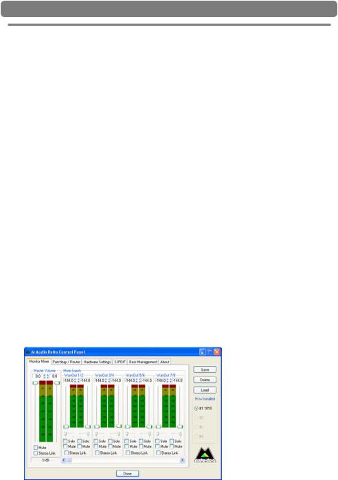
Monitor Mixer Tab
In order to hear your Monitor Mix, you first need to route the Monitor Mixer’s output signal to Delta 1010’s analog outputs 1/2 or to its S/PDIF output. This is done by selecting “Monitor Mixer” from the H/W Out 1/2 or H/W Out S/PDIF column in the Patchbay/Router tab.
Loading...