


™ |
Pub. 988-0154-173 |
Setup and Installation of
NMEA 2000® Networks
General Information
The NMEA 2000 Network DeviceNet is the communication bus standard developed by the National Marine Electronics Association (NMEA) for use in boats. Lowrance has introduced a line of products that can communicate over a NMEA 2000 network, helping you get the most out of this technology.
This instruction sheet will show how a NMEA 2000 network is created, configured and installed.
Read the next few pages to become familiar with some of the following terms: NMEA 2000 Network/LowranceNET, NMEA 2000 Bus/Network Bus, Network Backbone, Network Nodes and Linear Architecture.
NMEA 2000® Network or LowranceNET™
A NMEA 2000 network is a communications link between two or more devices that transfer NMEA 2000 information. LowranceNET is the NMEA 2000 networking system developed by Lowrance Electronics. A NMEA 2000 network functions like the phone wiring in a house. If, for example, you pick up a phone in the living room you will be able to hear the conversation someone is having on a phone in the bedroom.
In similar fashion, a NMEA 2000 network allows multiple display units to receive data from a GPS antenna or multiple sonar units to receive messages sent by a temperature sensor. A NMEA 2000 network gives you the flexibility to view engine diagnostics and fuel level data on digital gauges or display units located anywhere on your boat.
If you have a Lowrance display unit with a LGC-3000 GPS module installed, you have a NMEA 2000 network. The connectors and cables that came with your LGC-3000 function as a dedicated NMEA 2000 network, passing GPS data along the network to the GPS display unit. This is a simple form of a NMEA 2000 network.
On the other end of the scale is a large network bus. You can easily expand a network bus by adding multiple NMEA 2000 devices, even adding the same type of device more than once.
The network could share information with a sonar-GPS combo unit mounted in the dash, a sonar-only unit mounted at the stern and another display unit mounted on the bow. In that scenario, all three dis-
1
play units attached to the bus would have access to information from every sensor attached to the network. That is the advantage of a NMEA 2000 network.
WARNING:
The network MUST be installed in an area where it WILL NOT be submerged in standing water during normal operation of your vessel.
NOTE:
We recommend applying dielectric grease to all NMEA 2000 backbone and device connections. This will prevent moisture from corroding the connector terminals. Before connecting a T connector to another T connector or a NMEA 2000 device, apply a small amount of dielectric grease on the pin connectors of both male and female connectors.
Every display unit, gauge or sensor attached to the network can communicate with all other devices on the network. Location, speed and temperature, however, are not the only kinds of information that can be shared. Fuel Remaining data along with engine information like oil pressure and fuel efficiency are among a large number of data options that may be shared on the network.
NOTE:
Full Sonar Chart returns CANNOT be transmitted on a NMEA 2000 network, because they take too much bandwidth for the network. Every sonar display unit requires its own transducer. If, however, you have a sonar display unit (with sonar bottom lock) connected to the NMEA bus, it will share the digital depth with all display units on the network.
NMEA 2000 Bus or Network Bus
Technically, any physical cable used to transfer network information is a network bus, but in our documentation we use this term to refer to the standard manufacturer installation appearing in new boats. This network bus is an operational network cable, connected to a power supply and properly terminated, that will run the length of your boat. It will provide access to network nodes at various locations on the boat.
2
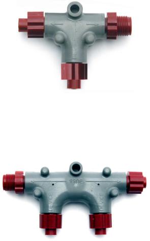
(Connection for backbone)  Sides of T
(Connection for devices)  Bottom of T
This T connector allows you to add a device to your NMEA 2000 bus creating a network node.
Network Backbone and Network Nodes
A network bus backbone consists of network cabling, terminators and T connectors. Network nodes are made by fitting T-shaped connectors into the backbone (using the sockets on the sides) and attaching any network device to the bottom of the T.
Double T connector
Staying with the previous phone wiring example, T connectors on the backbone are the equivalent of phone jacks spread throughout a house. To pick up a phone and be able to hear a conversation from another phone in the house, both phones have to be connected to the main phone line. In similar fashion, only sensors and display units plugged into the NMEA network can share information. The network backbone is like the phone wiring that runs throughout a home.
It connects the network nodes, allowing them to communicate across the network. Connections found in the middle of the bus could have T connectors or backbone network cable plugged into one or both sides. Connec-
3
tions at the end of a network will have the backbone cable plugged into one side and a terminator plugged into the other, as shown in the following figure.
|
|
Backbone cable |
|
Terminator at |
Double T |
(to rest of bus) |
|
the end of the |
|
||
connector |
Cable from |
||
backbone (bus) |
|||
|
|
sensor or |
|
Cap for unused |
|
display unit |
|
|
|
||
connector |
|
|
NMEA 2000 network node located at the end of a NMEA 2000 backbone.
NOTE:
If you have a double T Connector on your network that is not attached to a device, you must cap the unused connector with a NMEA 2000 cap. This will protect the pin connectors from corrosion. The NMEA 2000 cap looks like a terminator, but has "Cap" stamped into the connector housing.
All T connectors on your network probably will be connected to a device. If you want to add another node to a working network, add another T connector. T connectors may be purchased from LEI (ordering information appears on the back page of this booklet). If you are adding a Lowrance or LEI NMEA 2000 sensor, it will come with its own T connector.
Linear Architecture
NMEA 2000 networks are constructed using a linear pattern. It is important linear architecture is maintained when the network is modified or a node is added to the network.
Linear architecture refers to way the network's nodes are connected to the network backbone. Note that every T connector has two female sockets and one male socket. This means you could connect it in two different ways. Using linear construction, the T connectors will be connected side by side, leaving the bottom of the T available for connection to a display unit or NMEA 2000 device, like the "Correct installation" figure on the next page. A network built following a linear construction is easier to maintain and expand.
4

It also allows you to ensure the two terminators are at the ends of the backbone. If your installation does not follow a linear architecture, the network may not function.
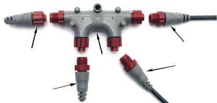
Backbone (Network bus)
This network bus has a cluster of single and double T connectors and is terminated on both ends. It is connected to a display unit and four NMEA 2000 devices.
You could use the recommended installation, plugging the sensor or display unit into the bottom of the T and the backbone cable into the side of the T. You also could plug the sensor or display unit into the side of the T and the backbone connection into the bottom of the T. The sockets would allow you to make that connection, but you would lose linear construction. Both installations are detailed in the following figures.
Correct installation |
|
Incorrect installation |
Sonar or GPS |
|
Sonar or GPS |
|
display unit |
|
display unit |
|
|
|
|
|
|
|
EP-35 |
LGC- |
|
temp sensor |
|
|
|
3000 |
|
|
EP-35 |
|
LGC- |
temp sensor |
|
|
|
3000 |
|
|
|
|
|
|
|
Two possible network designs. The design on the left maintains a linear architecture while the one on the right does not. You should always maintain linear architecture when building a NMEA 2000 network.
Both network designs in these images contain the same set of components. Both networks are terminated and all of the connectors are able
5
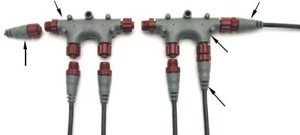
to be connected to one another, but the installation on the left comes to a clear end with terminators on each end of the backbone. The nonlinear installation on the right has no clear end, increasing the chance of an installation error.
It also makes network expansion more difficult and could even prevent the network from functioning.
Always maintain linear architecture when modifying your network. Make sure display units or sensors are attached to the bottom of the T. Attach the sides of the T to backbone extension cables, terminators or other T connectors – nothing else. All network examples in this document show networks built with a linear architecture.
Adding a Network Node
You can add a node to any existing connection, anywhere along the network backbone. This connection could be between a T connector and a terminator, between two T connectors, between a T connector and a backbone extension cable or between two extension cables. Wherever you want to add the new node, separate the sockets of the existing connection and install the T connector between them.
Use T-connector or double T connector to add |
Backbone cable |
device to bus (maintaining linear architecture) |
to rest of bus |
Existing network Attach node
terminator at end of bus
 Devices connect to double T connector
In this example, a new device is added to the NMEA 2000 bus by installing a T connector between a T connector and a terminator at the end of the backbone (network bus).
If you want to add a node at the end of the backbone (network bus) remove the terminator from the last connector, like the figure above. Install the new T connector and attach the terminator to the side of the connector.
6
 Loading...