


Pub. 988-0154-432
EP-60R Fuel Flow
Electronic Sensor
Installation, Configuration and Calibration Instructions
This document shows how to install an EP-60R Fuel Flow sensor and how to connect it to a NMEA 2000® network. It also provides instructions on how to configure and calibrate your fuel flow sensor with Lowrance digital gauges (LMF-200 & LMF-400) and display units.
NMEA 2000 is the communication bus standard developed by the National Marine Electronics Association (NMEA) for use in boats. Lowrance has introduced a line of products that can communicate over a NMEA 2000 network (LowranceNet).
All Lowrance NMEA 2000 capable devices are either NMEA 2000 certified or certification is pending.
Caution:
Installing LowranceNET NMEA 2000 devices is significantly different from installing earlier Lowrance components without NMEA 2000 features. You should read all of the installation instructions before proceeding. You should decide where to install all components before drilling any holes in your vessel.
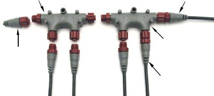
Fuel Flow module 
NMEA 2000 red connector
The EP-60R Fuel Flow sensor.
1
Some sonar or GPS display units may require a software upgrade to display NMEA 2000 data correctly. For free software upgrades or additional information on the LowranceNet NMEA 2000® network system, visit our web site, www.lowrance.com.
The EP-60R consists of a red cable connector and the sensor module. The sensor module contains a turbine to measure fuel flow and electronics which convert flow data to the NMEA 2000 data format. The cable length from the connector to the smart module is 10 feet (3 meters). The sensor is designed to work with gasoline only.
WARNING:
Do not use this sensor with diesel engine fuel systems. The EP-60R is designed only for gasoline engines.
This sensor has been optimized to measure flow rates between 0.6 to 45 gallons (US) per hour, but it will operate at flow rates outside that range. The sensor will add 0.5 PSI of back pressure on the fuel system with a flow rate of 20 gallons per hour. At the rate of 40 gallons per hour, the back pressure will be 1 PSI.
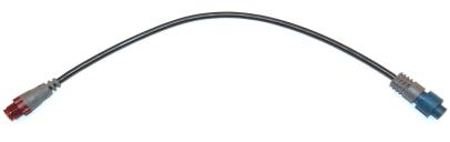
The EP-60R Fuel Flow, like the other LowranceNet Electronic Probe (EP) sensors, is designed for use with a NMEA 2000 network. Your sensor, however, is also compatible with LowranceNet blue connector networks. It can be added to a blue connector network by using a female red to female blue adapter cable. Your sensor MUST be connected to a NMEA 2000 network or it WILL NOT function.
The NMEA 2000 female red to female Blue adapter cable allows users to add red connector devices to a blue connector network.
Tools and Supplies
Your EP sensor packs with a T connector needed to attach it to a LowranceNET NMEA 2000 network. If this is the first sensor you are connecting, you may also need to purchase of a LowranceNET Node Kit.
2
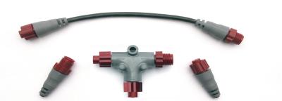
LowranceNET Node Kit for a NMEA 2000 network. Includes a 2-foot extension cable, T connector and two 120-ohm terminators.
For complete instructions on setting up a new NMEA 2000 network or expanding an existing one, see the other document packed with your EP-60R Fuel Flow, "Setup and Installation of NMEA 2000 Networks, General Information" part number 988-0154-173. If that document is unavailable, it can be downloaded free from the Lowrance web site.
Other supplies are not included, unless otherwise indicated. Required supplies include cable ties or other fasteners to secure the hose and cable; an inline fuel filter and any items needed to install it. Two 1" hose clamps are included with the sensor.
We assume you already have a fuel line installed. The EP-60R Fuel Flow was designed to fit a typical 3/8" SAE USCG Type A1 fuel hose. If your engine has different diameter hoses or metal fuel lines, a section of 3/8" fuel line must be installed between the sensor and the existing lines. Recommended tools are a flathead screwdriver to tighten the clamps and a knife to cut the fuel hose. If you need to route the sensor connector through a bulkhead, you will need a drill and a 3/4" drill bit.
Installation
Install one EP-60R sensor per engine. If you have multiple tanks, place the sensor after any Y or T in the line feeding the engine.
The sensor should be installed vertically, as close as possible to the fuel tank in an area where vibration is minimized. The housing has a molded-in, fuel flow direction arrow, which should be pointing up. Mount the sensor above the tank's maximum fuel level to avoid accidental fuel leakage in case the sensor becomes disconnected.
Caution:
Gasoline is extremely flammable. If possible, drain the fuel line before you start or shut any flow valves located at the tank. Keep sparks and flame away from the work area. After installation, remember to clean up any spilled fuel.
3

Cut the fuel hose where you intend to install the EP-60R sensor. Slide a clamp over the hose coming from the tank, then push the hose onto the bottom (inlet) hose barb.
Seat the hose flush against the sensor housing, then tighten the hose clamp. Attach the hose leading to the engine on the top (outlet) barb in the same way.
To engine
Flow direction
From tank
Push the fuel line onto the hose barb, then tighten the hose clamp. Orient the sensor vertically, with the flow arrow pointing up.
NOTE:
You must install an in-line fuel filter between the tank and the EP60R sensor. This will prevent a malfunction caused by contaminated fuel. Debris in unfiltered fuel can clog the sensor's turbine and result in rough performance or engine shut down.
As with any fuel system, we recommend you always carry onboard a spare fuel filter and an in-line 3/8" splice barb. This allows you to remove a clogged EP-60R fuel sensor or fuel filter and restore engine operation if the fuel filter fails. We strongly recommend that you inspect your entire fuel system at regular intervals.
Secure the sensor/hose assembly so the sensor remains in a vertical position with the flow direction up. Clamp the hose on either side of the sensor to the hull or bulkhead to minimize vibration.
Route the sensor's cable connector to the T on the network backbone where you intend to attach it, and plug it in. The sensor is ready to use.
4
Connecting to a NMEA 2000 Network
A NMEA 2000 network is a communications link between two or more devices that transfer NMEA 2000 information. LowranceNET is the NMEA 2000 networking system developed by Lowrance Electronics. A NMEA 2000 network functions like the phone wiring in a house.
If, for example, you pick up a phone in the living room you will be able to hear the conversation someone is having on a phone in the bedroom.
In similar fashion, a NMEA 2000 network allows multiple display units to receive data from a GPS antenna or multiple sonar units to receive messages sent by a temperature sensor. A NMEA 2000 network gives you the flexibility to view information like engine diagnostics and fuel level data on digital gauges or display units located anywhere on your boat.
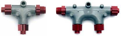
There are two types of LowranceNet red connectors: the single T connector (left) and the double T connector (right).
Network Backbone and Network Nodes
A network bus backbone consists of network cabling, terminators and T connectors. Network nodes are made by fitting T-shaped connectors into the backbone (using the sockets on the sides) and attaching any network device to the bottom of the T.
Staying with the previous phone wiring example, T connectors on the backbone are the equivalent of phone jacks spread throughout a house. To pick up a phone and be able to hear a conversation from another phone in the house, both phones have to be connected to the main phone line. In similar fashion, only sensors and display units plugged into the NMEA network can share information. The network backbone is like the phone wiring that runs throughout a home.
It connects the network nodes, allowing them to communicate across the network. Connections found in the middle of the bus could have T connectors or backbone network cable plugged into one or both sides.
Connections at the end of a network will have the backbone cable plugged into one side and a terminator plugged into the other, as shown in the following figure.
5
|
|
Backbone cable |
|
Terminator at |
Double T |
(to rest of bus) |
|
the end of the |
|
||
connector |
Cable from |
||
backbone (bus) |
|||
|
|
sensor or |
|
Cap for unused |
|
display unit |
|
|
|
||
connector |
|
|
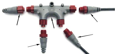
NMEA 2000 network node located at the end of a NMEA 2000 backbone.
NOTE:
If you have a double T Connector on your network that is not attached to a device, you must cap the unused connector with a NMEA 2000 cap. This will protect the pin connectors from corrosion. The NMEA 2000 cap looks like a terminator, but has "Cap" stamped into the connector housing.
All T connectors on your network probably will be connected to a device. If you want to add another node to a working network, add another T connector. T connectors may be purchased from LEI (ordering information appears on the back page of this booklet). If you are adding a Lowrance or LEI NMEA 2000 sensor, it will come with a T connector.
Adding a Network Node
You can add a node to any existing connection, anywhere along the network backbone. This connection could be between a T connector and a terminator, between two T connectors, between a T connector and a backbone extension cable or between two extension cables. Wherever you want to add the new node, separate the sockets of the existing connection and install the T connector between them. If you want to add a node at the end of the backbone (network bus) remove the terminator from the last connector, like the figure above. Install the new T connector and attach the terminator to the side of the connector.
6
Use T-connector or double T connector to add |
Backbone cable |
device to bus (maintaining linear architecture) |
to rest of bus |
Existing network Attach node
terminator at end of bus
 Devices connect to double T connector
In this example, a new device is added to the NMEA 2000 bus by installing a T connector between a T connector and a terminator at the end of the backbone (network bus).
Additional Network Information
For more information on creating or expanding a network refer to the NMEA 2000 network setup booklet, part number 988-0154-173, which came packed with this document.
7
Notes
8
LMF-200: EP-60R
Configuration & Calibration
This section covers how to use the EP-60R Fuel Flow with a LMF-200 Multi-function gauge.
NOTE:
You will notice the LMF-200 does not have an Exit key. Menus will time out after a preset amount of time (3, 5, 10 or 15 seconds). The default setting is 5 seconds. Refer to your LMF-200 instruction manual for more information on the Timeout feature.
LMF-200 Multi-function Digital Gauge
Boat Setup
If this is the first time you have turned on your LMF-200, you will have to complete Boat Setup before you will be able to configure or calibrate your fuel flow. If you have already completed Boat Setup, skip ahead to the segment covering EP-60R Fuel Flow Configuration.
To execute Boat Setup:
1.With Boat Setup highlighted on the screen, press MENU. The Boat Setup menu will appear, allowing you to select an engine-tank configuration to match the number of engines and fuel tanks on your vessel. Boat Setup options include: 1 En/1 Tk, 1 En/2 Tk, 2 En/1 Tk, 2 En/2 Tk, 3 En/1 Tk and 3 En/3 Tk.
2.Select the correct configuration option and press MENU. If you selected a configuration with more than one tank, the Tank Size menu will appear. (If you selected a single tank configuration you will be taken directly to the Tank Size window, where you can input the size of the tank.)
9
3.Select the tank you want to set up and press MENU, which will open the Tank Size window.
4.Use the UP and DOWN keys to input the number of gallons the tank will hold and press MENU. Repeat steps 3 and 4 for each additional tank. After all tanks have been set up, you will be directed to the main display.
Boat Setup Reset
If you want to access the Setup screen (Boat Setup) after an enginetank configuration has been chosen you will have to reset the configuration to default settings.
To reset engine tank configuration:
1.Press MENU, highlight SYSTEM SETUP and press MENU.
2.Choose ENG/TANK and press MENU twice. The following message will appear: Hit menu to reset Eng/Tnk.
3.Press MENU. The Setup screen will appear with Boat Setup highlighted.
Fuel Remaining Source (FRem Src)
The Fuel Remaining source function allows you to select the device used to measure the amount of fuel remaining in the tank. It will be set to fluid level by default.
To set Fuel Remaining Source to Fuel Flow (Eng/FFlow):
1.Press MENU, use the UP and DOWN keys to select SYSTEM SETUP and press MENU. Select FUEL MNGR and press MENU.
2.Highlight FREM SRC and press MENU. That will open the FRem Src menu, which has two options: Eng/FFlow and Fuel level.
3.Select ENG/FFLOW and press MENU. You can now view fuel remaining data from the EP-60R.
EP-60R Fuel Flow Configuration
The LMF-200 can support up to three engines with one fuel flow sensor for each engine. Each fuel flow has an internal menu with the following options: Unset Engine, Change Engine (multiple engines only), Fuel Warning, Reset and Reset Calibration.
To configure a fuel flow:
1.Press MENU, use the UP and DOWN keys to select SYSTEM SETUP and press MENU.
2.Highlight B. DEVICES and press MENU. After a few moments, the Bus Devices list will appear.
10
3. Select UNCFG FF and press MENU. The following message will appear: Hit Menu to Cfg Flow Sns. Press MENU and the Configuration options menu will appear.
NOTE:
If your unit is set to a Configuration Options menu configuring a fuel flow. The configured as Eng FFlow.
single-engine configuration, the will not appear when you are fuel flow will automatically be
4. Select the desired option and press MENU. You will be directed to the Bus Devices list. Configure remaining fuel flows by following the steps above.
To unconfigure a fuel flow:
You will use the Unset Engine command when you want to unconfigure a fuel flow.
To unset engine:
1.Press MENU, use the UP and DOWN keys to select SYSTEM SETUP and press MENU.
2.Highlight B. DEVICES and press MENU. After a few moments, the Bus Devices list will appear.
3.Select the fuel flow you want to unconfigure and press MENU.
4.Highlight UNSET ENGINE and press MENU which will launch the following message: Hit Menu to Unset Dev Name.
5.Press MENU and you will be taken back to the Bus Devices list. The newly unconfigured fuel flow will be displayed as UNCFG FF.
To reconfigure a fuel flow:
You will use the Change Engine command to reconfigure a Fuel Flow. Change Engine, however, will only appear on your LMF-200 menu if you have more than one engine. If you want to reconfigure a fuel flow, but all the fuel flows on your vessel are configured, you first will have to unconfigure a fuel flow to free up its configuration name.
If all three fuel flows are configured, which means there is no name configuration available, follow the first set of instructions. If the desired configuration name is available, follow the second set of instructions.
Change Engine (Active only with multiple-engine setting)
The Change Engine command allows you to change the configuration name of a fuel flow. The steps below show how to switch the configuration name of a fuel flow from Port to Starboard.
11
If all fuel flows configured (Configuration name unavailable):
1.Press MENU, use the UP and DOWN keys to select SYSTEM SETUP and press MENU.
2.Highlight B. DEVICES and press MENU. The Bus Devices list will appear.
3.Select the Port FFlow and press MENU.
4.Highlight UNSET ENGINE and press MENU. The following message will appear: Hit Menu to Unset Dev Name.
5.Press MENU and you will be taken back to the Bus Devices menu, where fuel flow (formerly Port FFlow) now will be displayed as UnCfg FFlow.
Remember: If the fuel flow you just unconfigured is not shown on the Bus Devices the list, you will have to refresh the list. Let the Bus Devices list time out then access it again.
6.Highlight STBD FFLOW and press MENU. Select CHANGE ENGINE and press MENU, which will open the Select Engine menu with up to three options: Port, Cen, Stbd.
7.Highlight PORT and press MENU.
8.You will be taken back to the Bus Devices list, where the fuel flow you selected (formerly Stbd FFlow) will now be shown as Port FFlow. If the newly configured fuel flow is not shown, refresh the Bus Devices list.
9.Now, select UNCFG FFLOW and press MENU. The following message will appear: Hit Menu to Cfg Flow Sns.
10.Press MENU, which will open the Select Engine menu. Highlight Starboard and press MENU. You will be directed to the Bus Devices list where the fuel flow now will be displayed as Stbd FFlow. If the newly configured fuel flow is not shown, refresh the Bus Devices list.
If configuration name available:
1.Press MENU, use the UP and DOWN keys to select SYSTEM SETUP and press MENU.
2.Highlight B. DEVICES and press MENU. After a few moments, the Bus Devices list will appear.
3.Highlight PORT FFLOW and press MENU. Select CHANGE ENGINE and press MENU, which will open the Select Engine menu with up to three options: Port, Cen, Stbd.
4.Highlight STARBOARD and press MENU.
12
5. You will be taken back to the Bus Devices list, where the fuel flow you selected (formerly Port FFlow) will be listed as Stbd FFlow. If the newly configured fuel flow is not shown, refresh the Bus Devices list.
Reset
The Reset command in the Fuel Flow level menu will clear the sensor’s configuration and calibration settings.
NOTE:
After using the Reset command, you will have to re-enter your engine-tank configuration. It, however, will not affect the configuration or calibration of other devices on the network.
To reset fuel flow settings:
1.Press MENU, use the UP and DOWN keys to select SYSTEM SETUP and press MENU.
2.Highlight B. DEVICES and press MENU. After a few moments, the Bus Devices list will appear.
3.Select the desired fuel flow and press MENU. Highlight RESET, press MENU and the following message will appear: Hit Menu to Rst Values.
4.Press MENU to reset fuel flow values to default settings.
EP-60R Fuel Flow Calibration
The factory calibration settings for the EP-60R Fuel Flow should be within 3 percent, so calibration will not be necessary in most cases.
NOTE:
Make sure the fuel flow has been set as the Fuel Remaining Source; otherwise, you will not be able to calibrate the fuel flow.
Fuel Flow Accuracy
To check fuel flow accuracy, you must add the Fuel Manager page to the page screen rotation and then customize it with Fuel Used data.
To add Fuel Manager page to the display:
1.Press MENU, use the UP and DOWN keys to select PAGES and press MENU, which will open the Pages menu with the following options: Add Page, Rem Page, Autoscroll and Set Pop-up.
2.Select ADD PAGE and press MENU.
3.Highlight FUEL MANAGER (Fuel Mngr) and press MENU. You will be taken back to the main display.
NOTE:
Make sure the Fuel Remaining Source has been set to Fuel Flow.
13
To customize Fuel Manager page:
1.With the Fuel Manager page displayed on the main display, press MENU, select CUSTOMIZE and press MENU.
2.Highlight USD (Fuel Used) and press MENU. If your unit is configured for more than one tank, the Select Tank menu will appear. (If your engine-tank configuration is set for one tank, you will be directed to the main display.)
3.Select the desired option and press MENU. You will be directed to the main display.
To check fuel flow accuracy:
1.Make sure your Fuel Remaining Source has been set to Fuel Flow then fill up the fuel tank connected to the EP-60R Fuel Flow you want to calibrate. Press MENU, use the UP and DOWN keys to select SYSTEM SETUP and press MENU.
2.Highlight FUEL MNGR and press MENU. Select REFILL T. and press MENU. If your unit is configured for more than one tank, the Select Tank menu will open. Select the tank you refilled and press MENU. (If your unit is configured for one tank, you will be taken directly to the Recalibration menu.)
3.The Recalibration (ReCal?) menu will appear with two options: Yes and No. Select NO and press MENU. The following message will appear:
Hit Menu if Tank filled up.
4.Press MENU, which will direct you to the main display.
5.Take your boat out, but use only ONE engine — the engine connected to the fuel flow. Burn at least 5 gallons of fuel, then fill up the tank again, noting how much fuel was added to the tank. Check the Fuel Management page for the fuel used figure calculated by the EP60R Fuel Flow.
6.Compare the amount of fuel you added when you filled up the tank with the EP-60R Fuel Used figure. If the difference between these two numbers is greater than 3 percent, you need to calibrate the unit.
To calibrate a fuel flow:
7.Press MENU, use the UP and DOWN keys to select SYSTEM SETUP and press MENU.
8.Highlight FUEL MNGR and press MENU. Select REFILL T. and press MENU. If your unit is configured for more than one tank, the Select Tank menu will open. Select the tank you refilled and press MENU. (If your unit is configured for one tank, you will be taken directly to the Recalibration menu.)
14
9. The Recalibration (The Recal?) menu will appear with two options: Yes and No. Select YES and press MENU.
NOTE:
If you do not have the fuel remaining source set to Eng/FFlow, the recalibration message will not appear.
10.The Filled Quantity window will appear. Use the UP and DOWN keys to input the amount of fuel you added to the tank and press MENU.
11.Repeat these steps for each fuel flow you want to calibrate.
Reset Calibration
The Reset Calibration command allows you to reset a fuel flow calibration back to factory defaults.
To Reset Calibration:
1.Press MENU, use the UP and DOWN keys to select SYSTEM SETUP and press MENU.
2.Highlight B. DEVICES and press MENU. Select the fuel flow you want to reset and press MENU.
3.Select RST CAL from the fuel flow menu and press MENU. The following message will appear: Hit Menu to Rst the Cal.
4.Press MENU to set calibration back to factory default settings. To recalibrate the fuel flow, refer to the fuel flow calibration instructions in this section.
Refill Tank (Refill T)
Since the EP-60R is not connected to the tank, its fuel information is not automatically updated when the tank is filled up. You must use the Refill Tank command to ensure the fuel information in the EP-60R stays consistent with the amount of fuel actually in the tank.
To refill tank:
1.Press MENU, use the UP and DOWN keys to select SYSTEM SETUP and press MENU. Highlight FUEL MNGR and press MENU.
2.Select REFILL T and press MENU. If your unit is configured for more than one tank, the Select Tank menu will appear with up to three options. (If you are using a single tank configuration, you will not see the Select Tank menu.)
3.Select the desired tank and press MENU. The following message will appear: Hit Menu if Tank filled up. Press MENU and you will be taken you back to the main display.
Partial Fill (Part Fill)
Since the EP-60R is not connected to the tank, its fuel information is not automatically updated when fuel is added to the tank. When you
15
 Loading...