


 Loading...
USER GUIDE
Wireless ADSL2+ Modem Router
Models: WAG120N, WAG160N v2, WAG320N
About This Guide
About This Guide |
Copyright and Trademarks |
|
|
|
|||||
Icon Descriptions |
|
Linksys, |
Cisco |
and |
the |
Cisco |
Logo |
||
|
are |
registered |
trademarks |
or |
|||||
|
|||||||||
While reading through the User Guide you may see |
|
trademarks of |
Cisco |
Systems, |
Inc. |
||||
|
and/or its affiliates in the U.S. and certain |
||||||||
various icons that call attention to specific items. Below is |
|
||||||||
|
other countries. Other brands and product |
||||||||
a description of these icons: |
|
||||||||
|
names are trademarks or registered |
||||||||
|
|
|
|
||||||
|
|
|
|
trademarks of their respective holders. |
|||||
|
NOTE: This check mark indicates that there is |
||||||||
|
|
Copyright © 2009 Cisco Systems, Inc. All |
|||||||
|
a note of interest and is something that you |
|
rights reserved. |
|
|
|
|
||
|
should pay special attention to while using the |
|
|
|
|
|
|
|
|
|
product. |
|
|
|
|
|
|
|
|
|
|
|
|
|
|
|
|
|
|
WARNING: This exclamation point indicates that there is a caution or warning of potential risk of bodily injury and/or it is something that could damage your property or product.
WEB: This globe icon indicates a noteworthy website address or e-mail address.
Online Resources
Website addresses in this document are listed without http:// in front of the address because most current web browsers do not require it. If you use an older web browser, you may have to add http:// in front of the web address.
Resource |
Website |
|
|
|
|
Linksys |
www.linksysbycisco.com |
|
|
|
|
Linksys |
www.linksysbycisco.com/international |
|
International |
||
|
||
Glossary |
www.linksysbycisco.com/glossary |
|
|
|
|
Network |
www.linksysbycisco.com/security |
|
Security |
||
|
||
|
|
|
Web Technical |
www.linksysbycisco.com/support |
|
Support |
||
|
||
|
|
Wireless ADSL2+ Modem Router |
i |

Table of Contents
Chapter 1: |
|
|
|
|
|
|
|
|
|
Product Overview |
|
|
|
|
|
|
|
|
1 |
Front Panel |
|
|
|
|
|
|
|
|
1 |
Back Panel . . . . . . . . . . . . . . |
. . . . . . . . |
. . |
. . |
. . |
. . |
. . |
. |
|
. 1 |
Placement Positions |
|
|
|
|
|
|
|
|
2 |
Chapter 2: |
|
|
|
|
|
|
|
|
|
Wireless Security Checklist |
|
|
|
|
|
|
|
|
3 |
General Network Security Guidelines |
|
|
|
|
|
|
|
|
3 |
Additional Security Tips . . . . . . . . |
. . . . . . . . |
. . |
. . |
. . |
. . |
. . |
. |
|
. 3 |
Chapter 3: |
|
|
|
|
|
|
|
|
|
Advanced Configuration |
|
|
|
|
|
|
|
|
4 |
How to Access the Utility |
|
|
|
|
|
|
|
|
4 |
Using the Utility . . . . . . . . . . . |
. . . . . . . . |
. . |
. . |
. . |
. . |
. . |
. |
. |
4 |
List of Screens in the Utility . . . . . . |
. . . . . . . . |
. . |
. . |
. . |
. . |
. . |
. . |
|
4 |
Setup Tab . . . . . . . . . . . . . . |
. . . . . . . . |
. . |
. . |
. . |
. . |
. . |
. |
|
. 5 |
Wireless Tab . . . . . . . . . . . . . |
. . . . . . . . |
. . |
. . |
. . |
. . |
. . |
. |
. |
5 |
Storage Tab (WAG320N Only) |
|
|
|
|
|
|
|
|
5 |
Security Tab . . . . . . . . . . . . . |
. . . . . . . . |
. . |
. . |
. . |
. . |
. . |
. |
. |
6 |
Access Restrictions Tab . . . . . . . . |
. . . . . . . . |
. . |
. . |
. . |
. . |
. . |
. . |
|
6 |
Applications & Gaming Tab . . . . . . |
. . . . . . . . |
. . |
. . |
. . |
. . |
. . |
. . |
|
6 |
Administration Tab |
|
|
|
|
|
|
|
|
6 |
Status Tab . . . . . . . . . . . . . . |
. . . . . . . . |
. . |
. . |
. . |
. . |
. . |
. |
|
. 7 |
Appendix A: |
|
|
|
|
|
|
|
|
|
Troubleshooting |
|
|
|
|
|
|
|
|
8 |
Appendix B: |
|
|
|
|
|
|
|
|
|
Specifications |
|
|
|
|
|
|
|
|
9 |
WAG120N . . . . . . . . . . . . . . |
. . . . . . . . |
. . |
. . |
. . |
. . |
. . |
. |
|
. 9 |
WAG160N v2 . . . . . . . . . . . . |
. . . . . . . . |
. . |
. . |
. . |
. . |
. . |
. . |
|
9 |
WAG320N . . . . . . . . . . . . . . |
. . . . . . . . |
. . |
. . |
. . |
. . |
. . |
. |
|
10 |
Appendix C: |
|
|
|
|
|
|
|
|
|
Regulatory Information |
|
|
|
|
|
|
|
11 |
|
European Union . . . . . . . . . . . |
. . . . . . . . |
. . |
. . |
. . |
. . |
. . |
. |
.11 |
|
Australia . . . . . . . . . . . . . . |
. . . . . . . . |
. . |
. . |
. . |
. . |
. . |
. . |
|
18 |
New Zealand . . . . . . . . . . . . |
. . . . . . . . |
. . |
. . |
. . |
. . |
. . |
. . |
|
18 |
United States of America |
|
|
|
|
|
|
|
|
18 |
Canada . . . . . . . . . . . . . . . |
. . . . . . . . |
. . |
. . |
. . |
. . |
. . |
. |
.20 |
|
Wireless ADSL2+ Modem Router |
ii |

Chapter 1
Product Overview
Chapter 1:
Product Overview
Thank you for choosing the Wireless ADSL2+ Modem Router. This device lets you access the Internet via a wireless connection or through one of its four switched ports. You can also use it to share resources such as computers, printers and files. A variety of security features, such as WPA2™ security, a Stateful Packet Inspection (SPI) firewall and NAT technology, help to protect your data and your privacy while online. Configuration is easy using the provided browser-based utility.
Front Panel
Power (WAG120N: Green/Amber; WAG160N v2 and WAG320N: Green/Red) The Power LED is continuously lit green while the device is powered on. The LED is lit amber (WAG120N) or red (WAG160N v2 and WAG320N) if a POST (Power On Self Test) failure or device malfunction occurs.
Ethernet 1-4 (Green) These numbered LEDs, one for each of the numbered ports on the Modem Router’s back panel, serve two purposes. If the LED is continuously lit, the Modem Router is successfully connected to a device through that port. It flashes to indicate network activity over that port.
NOTE: The Ethernet 1 LED is lit amber when the WAN link is established on that port.
Wi-Fi Protected Setup™ Button (WAG120N: Green/Amber; WAG160N v2 and WAG320N: Green) Press this button to have Wi-Fi Protected Setup™ search for your Wi-Fi Protected Setup™-supported wireless device. The LED is continuously lit green when a Wi-Fi Protected Setup™ connection is successfully established. The LED blinks slowly while Wi-Fi Protected Setup™ is setting up a connection, and is lit amber (WAG120N) or blinks rapidly (WAG160N v2 and WAG320N) if an error occurs. The LED is off when Wi-Fi Protected Setup™ is idle.
NOTE: Wi-Fi Protected Setup™ is a feature that makes it easy to configure your wireless network and its security settings.
USB (WAG320N only) (Green) The USB LED lights up when a USB device is connected to the
Modem Router through the USB port.
Wireless (Green) The Wireless LED lights up
 when the wireless feature is enabled. It flashes when the Modem Router is actively sending or receiving data over the network.
DSL (Green) The DSL LED lights up whenever
there is a successful DSL connection. The LED flashes green while the Modem Router is establishing the ADSL connection.
Internet (Green/Red) The Internet LED lights up green and stays on when a connection is made through the Internet port. It flashes to indicate network activity over the Internet port. The LED is lit red when an authentication error occurs.
Back Panel
 DSL The DSL port connects to the ADSL line.
Ethernet 4, 3, 2, 1 The Ethernet ports (4, 3, 2, 1) connect the Modem Router to wired computers and other Ethernet network devices.
NOTE: The |
Ethernet |
1 |
port |
can |
||
also |
be |
configured |
as |
the |
WAN |
|
port. |
To |
do |
this, access |
the |
Web- |
|
based utility (refer to “Chapter 3: Advanced Configuration” on page 4), then select the Setup > Ethernet tab.
USB (WAG320N only) The USB port connects the Modem Router to a hard drive or flashbased USB storage device.
Reset There are two ways to reset the Modem Router’s factory defaults. Either press and hold the Reset button for approximately five seconds, or restore the defaults from the
Administration > Factory Defaults screen of the Modem Router’s web-based utility.
Power The Power port is where you will connect the power adapter.
On/Off Button Press the On/Off button to turn power to the device on or off.
Wireless ADSL2+ Modem Router |
1 |
Chapter 1
Product Overview
Placement Positions
There are two ways to physically install the device. The first way is to place the device horizontally on a surface. The second way is to mount the device on a wall.
The best place for the device is usually at the center of your wireless network, within range of all of your wireless devices.
Horizontal Placement
The device has four rubber feet on its bottom panel. Place the device on a level surface near an electrical outlet.
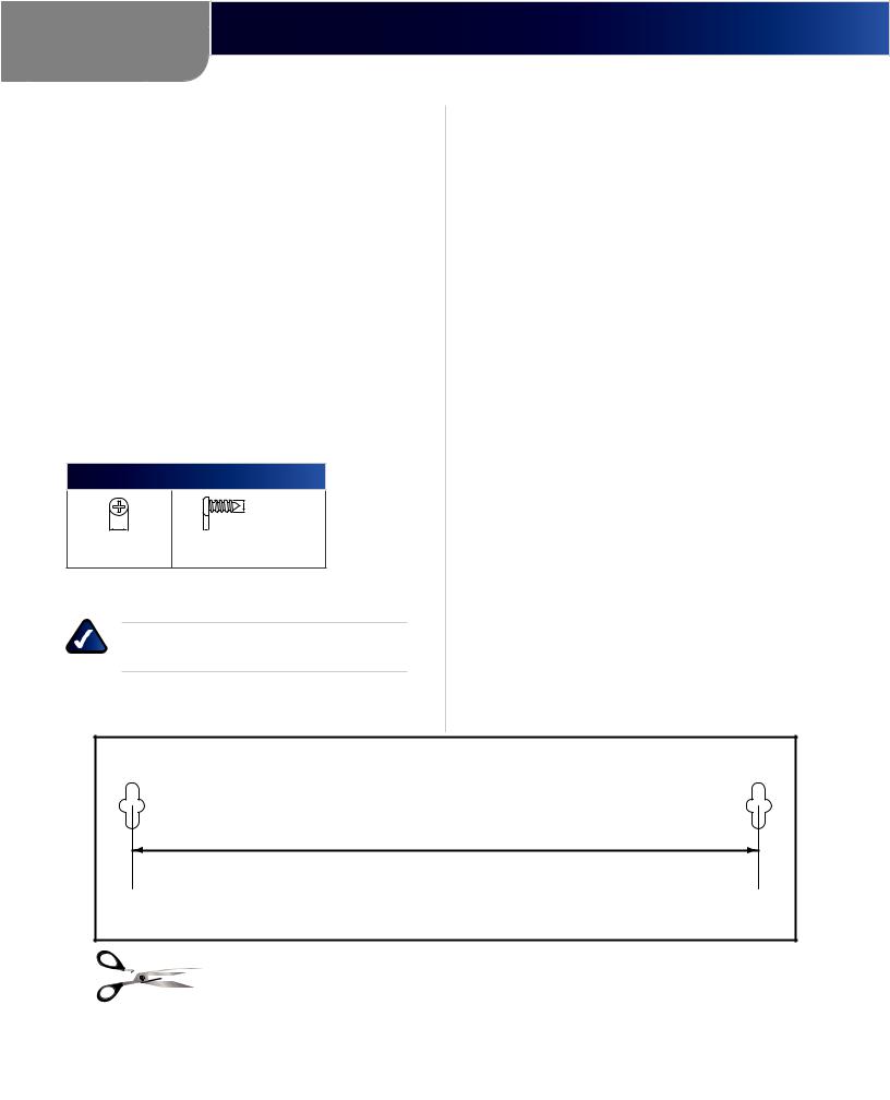
Wall-Mounting Placement
The device |
has two wall-mount slots on its bottom |
panel. The |
distance between the slots is 152 mm |
(6 inches). |
|
Two screws are needed to mount the device.
Suggested Mounting Hardware
4-5 mm |
1-1,5 mm |
-3,0 mm |
|
2,5 |
|||
|
|
††Note: Mounting hardware illustrations are not true to scale.
NOTE: Cisco is not responsible for damages incurred by insecure wall-mounting hardware.
Follow these instructions:
1.Determine where you want to mount the device. Make sure that the wall you use is smooth, flat, dry, and sturdy. Also make sure the location is within reach of an electrical outlet.
2.Drill two holes into the wall. Make sure the holes are 152 mm (6 inches) apart.
3.Insert a screw into each hole and leave 3 mm (0,12 inches) of its head exposed.
4.Maneuver the device so the wall-mount slots line up with the two screws.
5.Place the wall-mount slots over the screws and slide the device down until the screws fit snugly into the wall-mount slots.
152 mm
Wall Mounting Template
Wireless ADSL2+ Modem Router |
2 |

Chapter 2
Wireless Security Checklist
Chapter 2:
Wireless Security Checklist
Wireless networks are convenient and easy to install, so homes with high-speed Internet access are adopting them at a rapid pace. Because wireless networking operates by sending information over radio waves, it can be more vulnerable to intruders than a traditional wired network. Like signals from your cellular or cordless phones, signals from your wireless network can also be intercepted. Since you cannot physically prevent someone from connecting to your wireless network, you need to take some additional steps to keep your network secure.
1.Change the default wireless network name or SSID
Wireless devices have a default wireless network name or Service Set Identifier (SSID) set by the factory. This is the name of your wireless network, and can be up to 32 characters in length. Linksys by Cisco wireless products use linksys as the default wireless network name. You should change the wireless network name to something unique to distinguish your wireless network from other wireless networks that may exist around you, but do not use personal information (such as your Social Security number) because this information may be available for anyone to see when browsing for wireless networks.
 2. Change the default password
For wireless products such as access points, routers, and modem routers, you will be asked for a password when you want to change their settings. These devices have a default password set by the factory. The default password is admin. Hackers know these defaults and may try to use them to access your wireless device and change your network settings. To thwart any unauthorized changes, customize the device’s password so it will be hard to guess.
 3. Enable MAC address filtering
Linksys by Cisco routers and modem routers give you the ability to enable Media Access Control (MAC) address filtering. The MAC address is a unique series of numbers and letters assigned to every networking device. With MAC address filtering enabled, wireless network access is provided solely for wireless devices with specific MAC addresses. For example, you can specify the MAC address of each computer in your home so that only those computers can access your wireless network.
 4. Enable encryption
Encryption protects data transmitted over a wireless network. Wi-Fi Protected Access™ (WPA™/WPA2™) and Wired Equivalency Privacy (WEP) offer different levels of security for wireless communication.
A network encrypted with WPA™/WPA2™ is more secure than a network encrypted with WEP, because WPA™/WPA2™ uses dynamic key encryption. To protect the information as it passes over the airwaves, you should enable the highest level of encryption supported by your network equipment.
WEP is an older encryption standard and may be the only option available on some older devices that do not support WPA™.
General Network Security Guidelines
Wireless network security is useless if the underlying network is not secure.
•• Password protect all computers on the network and individually password protect sensitive files.
•• Change passwords on a regular basis.
•• Install anti-virus software and personal firewall software.
•• Disable file sharing (peer-to-peer). Some applications may open file sharing without your consent and/or knowledge.
Additional Security Tips
•• Keep wireless routers, access points, or modem routers away from exterior walls and windows.
•• Turn wireless routers, access points, or modem routers off when they are not being used (at night, during vacations).
•• Usestrongpassphrasesthatareatleasteightcharacters in length. Combine letters and numbers to avoid using standard words that can be found in the dictionary.
WEB:Formoreinformationonwirelesssecurity, visit www.linksysbycisco.com/security
Wireless ADSL2+ Modem Router |
3 |

Chapter 3
Advanced Configuration
Chapter 3:
Advanced Configuration
After you finish running the Setup Wizard on the Setup CD-ROM, the device is ready for use. To change the device’s advanced settings, access the Configuration Utility via a web browser on a computer connected to the device.
NOTE FOR USERS IN NEW ZEALAND: Refer to the Note in Setup > Basic Setup, page 5 for setup instructions specific to your country.
How to Access the Utility
Launch the web browser on your computer, and enter the device’s default IP address, 192.168.1.1, in the Address field. Then, press Enter.
A login screen appears. Use the default user name and password, admin, unless you changed them when you ran the Setup Wizard. (You can set a new user name and password from the Administration tab’s Management screen.) Click OK to continue.
Login
If you are unable to log in, press the Reset button on the back panel for at least 5 seconds, then wait for the device to reset and try again.
Using the Utility
Immediately after login, the Basic Setup screen appears. Near the top of the screen is a bar with selectable tabs. Use these tabs to navigate within the Utility. The primary tabs indicate the Utility’s main configuration categories. Each primary tab has one or more secondary tabs that provide access to the primary tab’s configuration screens.
Primary Tabs
Setup Wireless Storage Security |
Access Applications & |
Administration Status |
|
Restrictions |
Gaming |
||
Basic Setup Ethernet DDNS MAC Address Clone |
Advanced Routing |
||
Secondary Tabs
Navigation Tabs
To access a screen, click the appropriate primary tab, then click the appropriate secondary tab. The screen will appear, with its primary and secondary tabs highlighted.
List of Screens in the Utility
The screens are organized hierarchically as listed below. (Some screens may not apply to all models.)
Setup Tab
Setup > Basic Setup Setup > Ethernet Setup > DDNS
Setup > MAC Address Clone
Setup > Advanced Routing
Wireless Tab
Wireless > Basic Wireless Settings Wireless > Wireless Security Wireless > Wireless MAC Filter
Wireless > Advanced Wireless Settings
Storage Tab (WAG320N Only)
Storage > Disk Management Storage > Shared Folder Storage > Administration Storage > Media Server
Security Tab
Security > Firewall
Security > VPN Passthrough
Access Restrictions Tab
Access Restrictions > Internet Access Policy
Applications & Gaming Tab
Applications & Gaming > Single Port Forwarding Applications & Gaming > Port Range Forwarding Applications & Gaming > Port Range Triggering Applications & Gaming > DMZ
Applications & Gaming > QoS
Administration Tab
Administration > Management Administration > Reporting Administration > Diagnostics Administration > Back Up & Restore Administration > Factory Defaults Administration > Firmware Upgrade Administration > Language
Status Tab
Status > Modem Router
Status > Local Network Status > Wireless Network Status > DSL Connection
Wireless ADSL2+ Modem Router |
4 |
Loading...