


 Loading...
ADMIN GUIDE
BUSINESS SERIES
48-port 10/100/1000 Ethernet
Switch
Model: SGE2010/SGE2010P

Table of Contents
1 Introduction . . . . . . . . . . . . . . . . . . . . . . |
. . . . . . 1 |
What’s in this User Guide? |
1 |
2 Getting to Know the SGE2010/SGE2010P . . . . . . . . |
. . . . . . 2 |
SGE2010/P Front Panel |
2 |
SGE2010/P Back Panel |
3 |
3 Connecting Devices to the SGE2010/SGE2010P . . . . . |
. . . . . . 4 |
Sample Network Configuration |
4 |
Maximum Cabling Distances |
4 |
Before You Install the Switch... |
5 |
Placement Options |
5 |
Desktop Placement |
5 |
Rack-Mount Placement |
6 |
Wall-Mount Placement |
7 |
Connecting the Cables |
7 |
4 Using the Console . . . . . . . . . . . . . . . . . . . |
. . . . . . 9 |
Connecting to Your Switch with HyperTerminal |
9 |
Connecting to the Switch with Telnet |
12 |
Logging On to the Console |
12 |
Selecting Menu Options and Actions |
12 |
Using the Switch Main Menu |
13 |
System Configuration |
13 |
System Information |
14 |
Management Settings |
16 |
Username & Password Settings |
21 |
Security Settings |
22 |
VLAN Management |
25 |
IP Configuration |
26 |
File Management |
40 |
Restore System Default Settings |
43 |
Reset to Factory Settings |
43 |
Reboot System |
43 |
Stack Configuration |
44 |
Port Status |
44 |
SGE2010/SGE2010P Administration Guide |
i |

Table of Contents
Port Status |
45 |
PoE Status |
45 |
Port Configuration |
46 |
Port Settings |
46 |
PoE Settings |
47 |
System Mode (Layer 2 / Layer 3) Selection |
48 |
Help |
49 |
Logout |
50 |
5 Web Utility Configuration . . . . . . . . |
. . . . . . . . . . . . 51 |
Connecting to the Switch with the Web-Based Utility |
51 |
Using Menus in the Web-Based Utility |
51 |
Viewing On-line Help |
52 |
A Contacts . . . . . . . . . . . . . . . . . |
. . . . . . . . . . . . 53 |
US/Canada Contacts |
53 |
B C
Customer Site Survey. . . . . . . . . . . . . . . . . . . . . . . 54
Warranty Information |
. . . . . . . . . . . . . . . . . . . . . . 56 |
Limited Warranty |
56 |
Exclusions and Limitations |
56 |
Obtaining Warranty Service |
57 |
Technical Support |
57 |
D Federal Communication Commission Interference Statement |
. . |
58 |
Industry Canada Statement |
|
58 |
EC Declaration of Conformity (Europe) |
|
58 |
E Specifications . . . . . . . . . . . . . . . . . . . . . . . . |
. . |
59 |
SGE2010/SGE2010P Administration Guide |
ii |

1
Introduction
Introduction
What’s in this User Guide?
Welcome
Thank you for choosing a Linksys Switch. This Switch will allow you to quickly and economically expand your Linksys system.
This new Linksys rack mount Switch delivers non-blocking, wire speed switching for your network clients, plus multiple options for connecting to your network backbone. Forty eight ports wire up your workstations or connect to other Linksys switches or devices.
The Switch features monitoring and configuration via your web browser, making it easy to manage your Switch. Or if you prefer, you can use the console interface to configure the Switch.
Use the instructions in this guide to help you connect the switch, set it up, and configure it to bridge your different networks. These instructions should be all you need to get the most out of the Switch.
What’s in this User Guide?
This user guide covers the steps for setting up and using the Switch.
•Chapter 2, "Getting to Know the SGE2010/SGE2010P"
This chapter describes the ports, LEDs, and other features on the front and back panels of the switch.
•Chapter 3, "Connecting Devices to the SGE2010/SGE2010P"
This chapter explains how to physically connect your network devices to the switch.
•Chapter 4, "Using the Console"
This chapter describes the use of the switch console, which allows you to perform basic configuration of the switch.
•Chapter 5, "Web Utility Configuration "
This chapter provides an introduction to the features of the web-based configuration utility.
•Appendix A, "Contacts"
•Appendix B, "Customer Site Survey"
•Appendix C, "Warranty Information"
•Appendix D, "Federal Communication Commission Interference Statement"
•Appendix E, "Specifications"
SGE2010/SGE2010P Administration Guide |
1 |

2 |
Getting to Know the SGE2010/SGE2010P |
|
Getting to Know the SGE2010/SGE2010P
This chapter describes the ports, LEDs, and other features on the front and back panels of the switch.
The SGE2010 and SGE2010P are 48-port, layer-2 Ethernet switches that affordably expand the capability of the Linksys system. These two versions are functionally identical except the SGE2010P model offers Power-over-Ethernet (PoE) which can be used to supply power to various Linksys products over Ethernet cable.
SGE2010/P Front Panel
Feature |
Description |
|
|
Reset |
The Switch can be reset by inserting a pin or paper clip into the RESET |
|
opening. |
|
CAUTION: If the RESET switch is pressed for more than 10 seconds, the |
|
Switch will reset to its default settings. All customized user settings will be |
|
lost. |
|
|
LEDs |
The Switch uses Light Emitting Diodes (LEDs) to indicate the status of |
|
numerous functions. These functions are listed below. |
|
|
PWR |
A green PWR LED lights up to indicate that the Switch is powered on. |
|
|
FAN |
A green FAN LED lights up to indicate that the cooling fan is operating |
|
properly. A blinking red FAN LED indicates that the cooling fan has failed. |
|
|
RPS |
A green RPS LED lights up to indicate that RPS is connected and operating |
|
properly. A blinking red RPS LED indicates an RPS fault. |
|
|
MST |
A green MST LED indicates that this Switch is a stack master. |
|
|
Stack ID |
A green Stack ID LED indicates that this Switch is stacked and the |
|
corresponding number indicates its stack ID. |
|
|
Act/Link |
The green Act/Link LEDs light up to indicate a functional network link |
|
through the corresponding port with an attached device. The Act |
|
(Activity) LEDs flash to indicate that the Switch is actively sending or |
|
receiving data over that port. |
|
|
Speed |
On the SGE2010, a green Speed LED indicates that the port is linked to a |
|
100Mbps device. |
|
|
PoE |
On the SGE2010P, a green PoE LED indicates that PoE is active on that port. |
|
|
SGE2010/SGE2010P Administration Guide |
2 |

Getting to Know the SGE2010/SGE2010P
Feature |
Description |
|
|
1-48 |
The Switch is equipped with 48 auto-sensing, Ethernet (802.3) network |
|
ports, which use RJ-45 connectors. The Fast Ethernet ports support |
|
network speeds of 10Mbps, 100Mbps, or 1000Mbps. They can operate in |
|
half and full-duplex modes. Auto-sensing technology enables each port to |
|
automatically detect the speed of the device connected to it, and adjust |
|
its speed and duplex accordingly. |
|
The switch can deliver a maximum of 15.4W to a PoE port. With regular AC |
|
power supply, there is 360W available to all PoE ports, and 280W available |
|
with redundant power supply. |
|
Ports 45, 46, 47 and 48 are shared with miniGBIC1, miniGBIC2, miniGBIC3, |
|
and miniGBIC4, respectively. |
|
NOTE: A switch is in stacking mode by default. In stacking mode, ports 24 |
|
and 48 are reserved for use as stacking ports. For more information |
|
about stacking, refer to the SFE2010/SGE2010 Reference Guide. |
|
|
miniGBIC1-4 |
The switch provides four mini-GBIC ports. The mini-GBIC (gigabit interface |
|
converter) port is a connection point for a mini-GBIC expansion module, |
|
so the Switch can be uplinked via fiber to another switch. Each mini-GBIC |
|
port provides a link to a high-speed network segment or individual |
|
workstation at speeds of up to 1000Mbps. |
|
Use the Linksys MGBT1, MGBSX1, or MGBLH1 mini-GBIC modules with the |
|
switch. The MGBSX1 and the MGBLH1 require fiber cabling with LC |
|
connectors, while the MGBT1 requires a Category 5e Ethernet cable with |
|
an RJ-45 connector. |
|
NOTE: If shared ports are both connected, then the miniGBIC port has |
|
priority. |
|
|
SGE2010/P Back Panel
Feature |
Description |
|
|
Power |
The Power port is where you will connect the power cord. |
|
|
Console |
The Console port is where you can connect a serial cable to a PC’s serial |
|
port for configuration using your PC’s HyperTerminal program. Refer to |
|
Chapter 4: Using the Console Interface for Configuration for more |
|
information. |
|
|
RPS |
Redundant Power Supply (Linksys RPS1000) |
|
|
SGE2010/SGE2010P Administration Guide |
3 |
3 |
Connecting Devices to the SGE2010/SGE2010P |
Sample Network Configuration |
Connecting Devices to the SGE2010/ SGE2010P
This chapter explains how to physically connect your network devices to the switch.
•”Sample Network Configuration,” on page 4
•”Maximum Cabling Distances,” on page 4
•”Before You Install the Switch... ,” on page 5
•”Placement Options,” on page 5
•”Connecting the Cables,” on page 7
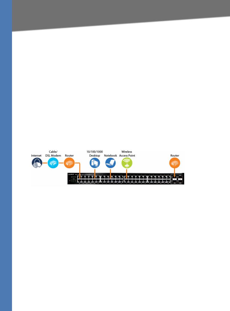
Sample Network Configuration
For an example of a possible network configuration, see the application diagrams shown below.
Maximum Cabling Distances
When you connect your network devices, make sure you don’t exceed the maximum cabling distances, which are listed in the following table:
From |
To |
Maximum Distance |
|
|
|
|
|
|
Switch |
Switch or Hub* |
100 meters (328 feet) |
|
|
|
Hub |
Hub |
5 meters (16.4 feet) |
|
|
|
Switch or Hub |
Computer |
100 meters (328 feet) |
|
|
|
*A hub refers to any type of 100Mbps hub, including regular hubs and stackable hubs. A 10Mbps hub connected to another 10Mbps hub can span up to 100 meters (328 feet).
SGE2010/SGE2010P Administration Guide |
4 |

Connecting Devices to the SGE2010/SGE2010P
Before You Install the Switch...
Before You Install the Switch...
When you choose a location for the switch, observe the following guidelines:
•Make sure that the switch will be accessible and that the cables can be easily connected.
•Keep cabling away from sources of electrical noise, power lines, and fluorescent lighting fixtures.
•Position the switch away from water and moisture sources.
•To ensure adequate air flow around the switch, be sure to provide a minimum clearance of two inches (50 mm).
•Connect the supplied power cord to the switch’s power port, and plug the other end into an electrical outlet.
CAUTION: Make sure you use the power cord that is supplied with the switch. Use of a different power cord could damage the switch.
Placement Options
Before connecting cables to the Ethernet switch, first you will physically install the Ethernet switch. Either set the Ethernet switch on its four rubber feet for desktop placement, mount it in a standard-sized, 19-inch wide for rack-mount placement, or mount it on a wall with the wallmount brackets provided.
NOTE: The four supplied mounting brackets can be used for either wall mount or rack mount installations.
Desktop Placement
1. Attach the rubber feet to the recessed areas on the bottom of the Ethernet switch.
2. Place the Ethernet switch on a desktop near an AC power source.
SGE2010/SGE2010P Administration Guide |
5 |

Connecting Devices to the SGE2010/SGE2010P
Placement Options
CAUTION: Keep enough ventilation space for the Ethernet switch so it does not exceed the environmental restrictions mentioned in the specifications.
Rack-Mount Placement
To mount the Ethernet switch in any standard-sized, 19-inch wide, (each Ethernet switch requires 1RU of space in the rack), follow these instructions:
1.Remove the four front screws on one side of the Ethernet switch. Retain the screws for reinstallation.
2.Place one of the supplied spacers on the side of the Ethernet switch so the four holes align to the screw holes.
3.Place a rack mount bracket next to the spacer and reinstall the four screws (removed in step 1).
4.Repeat steps 2 through 3 for the other side of the Ethernet switch.
5.Attach the Ethernet switch to the rack using the supplied screws.
SGE2010/SGE2010P Administration Guide |
6 |
Connecting Devices to the SGE2010/SGE2010P
Connecting the Cables
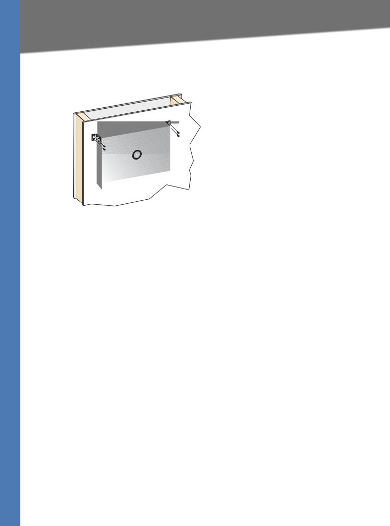
Wall-Mount Placement
1.On one of the side corners, remove the four front screws on of the Ethernet switch. Retain the screws for re-installation.
NOTE: The Ethernet switch, shown below, is mounted with the ports located on top. When the switch is mounted to a wall, the ports can be oriented in any direction.
2.Place one of the supplied spacers on the side of the Ethernet switch so the four holes align to the screw holes.
3.Place a rack mount bracket next to the spacer and reinstall the four screws (removed in step 1). The wall mount brackets should point towards the bottom of the Ethernet switch.
4.Repeat steps 1 through 3 for the other corners of the Ethernet switch.
5.Attach the Ethernet switch to a wall with appropriate screws (not supplied).
CAUTION: Ensure that the Ethernet switch is securely attached to the wall.
Connecting the Cables
To connect network devices to the Ethernet switch, follow these instructions:
1.For 10/100Mbps devices, connect a Category 5 Ethernet network cable to one of the numbered ports on the Ethernet switch. For a 1000Mbps device, connect a Category 5e Ethernet network cable to one of the uplink ports on the Ethernet switch.
NOTE: If connecting an Ethernet switch to an SVR3000 router, connect it to a Cascade port on the SVR3000.
2.Connect the other end to a PC or other network device.
3.Repeat steps 2 and 3 to connect additional devices.
4.If you are using the mini-GBIC port, then insert the mini-GBIC module to the mini-GBIC port. For detailed instructions, refer to the documentation supplied with the mini-GBIC module.
SGE2010/SGE2010P Administration Guide |
7 |
Connecting Devices to the SGE2010/SGE2010P
Connecting the Cables
CAUTION: Observe the orientation of the mini-GBIC module before inserting it into a miniGBIC port. The bottom mini-GBIC ports are upside down in relation to the top mini-GBIC ports.
5.If you use the console interface to configure the Ethernet switch, then connect the supplied serial cable to the console port (located on the back of the Ethernet switch), and tighten the captive retaining screws. Connect the other end to your PC’s serial port. (The PC must be running VT100 terminal emulation software, such as HyperTerminal.)
6.Connect the supplied power cord to the power port, and plug the other end into an electrical outlet.
CAUTION: Make sure you use the power cord that is supplied with the Ethernet switch. Use of a different power cord could damage the Ethernet switch.
7.Power on the network devices connected to the Ethernet switch. Each active port’s corresponding Act/Link LED will light up on the Ethernet switch. If a port has an active Gigabit connection, then its corresponding Gigabit LED will also light up.
8.Proceed as needed:
•If you will use the console interface to configure the Ethernet switch, proceed to ”Console Configuration” section on page 33 for directions.
•If you use the Web-based Utility to configure the Ethernet switch, proceed to ”Web Utility Configuration” section on page 50.
SGE2010/SGE2010P Administration Guide |
8 |

4 |
Using the Console |
Connecting to Your Switch with HyperTerminal |
Using the Console
This chapter describes the use of the switch console, which allows you to perform basic configuration of the switch.
The switch features a menu-driven console interface for basic configuration of the switch and management of your network.This chapter describes console interface configuration. Configuration can also be performed through the web utility, which is covered in the next chapter.
•”Connecting to Your Switch with HyperTerminal,” on page 9
•”Connecting to the Switch with Telnet,” on page 12
•Logging On to the Console (see page 12)
•Selecting Menu Options and Actions (see page 12)
•Using the Switch Main Menu (see page 13)
•System Configuration (see page 13)
•Port Status (see page 44)
•Port Configuration (see page 46)
•System Mode (Layer 2 / Layer 3) Selection (see page 48)
•Help (see page 49)
•Logout (see page 50)
Connecting to Your Switch with HyperTerminal
You can use the HyperTerminal to connect to your switch.
NOTE: The switch also can be configured through a telnet connection. Telnet to the switch IP address 192.168.1.254. Then, press the Enter key. The default logon ID is admin with a blank password.
Before you use HyperTerminal to connect to your switch for the first time, you must configure the application on your PC. You can save the settings to use each time you connect to your switch.
SGE2010/SGE2010P Administration Guide |
9 |

Using the Console
Connecting to Your Switch with HyperTerminal
1.Click the Start button. Choose Programs > Accessories > Communications > HyperTerminal.
2.On the Connection Description screen, type a name for this connection, select an icon, and then click OK.
3.On the Connect To screen, use the Connect using drop-down list to select a port to communicate with the switch: COMn, or TCP/ IP.
SGE2010/SGE2010P Administration Guide |
10 |
Using the Console
Connecting to Your Switch with HyperTerminal
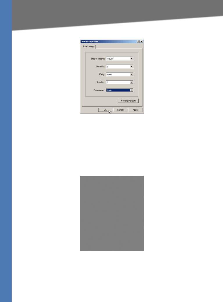
4. Set the serial port settings as follows:
•Bits per second: 115200
•Data bits: 8
•Parity: None
•Stop bits: 1
•Flow control: None
5.Then, click the OK button.
6.Optionally, on the File menu, click Save to save these settings. The next time that you need to connect to the console, you can open this saved connection.
SGE2010/SGE2010P Administration Guide |
11 |

Using the Console
Connecting to the Switch with Telnet
Connecting to the Switch with Telnet
You can connect to the switch with telnet.
1.Open a command line editor and enter telnet <switch ip address>. Then, press the Enter key.
2.When the Login screen appears, select Edit and enter admin in the User Name field. Leave the Password field blank.
3.Press the Esc key to return to the Login screen.
4.Select Enter to enter the CLI interface.
NOTE: The Username & Password Settings screen can also be used to set passwords for other users.
Logging On to the Console
1.Start HyperTerminal and open the connection that you configured previously.
2.When the blinking cursor appears, press the Enter key.
3.When prompted to login, enter the default login and password: admin
The Switch Main Menu appears.
Selecting Menu Options and Actions
Within the Console Interface, menus list options in numeric order. Actions appear at the end of the screen. To select menu options and actions, use the following keys on your keyboard:
Key |
Function |
|
|
Arrow keys |
Move the cursor up, down, left, or right. |
|
|
Number key |
Press the menu number and then press Enter key to select a menu |
|
option. |
|
|
Tab |
Move the cursor from one field to the next on an editing screen. |
|
|
Enter |
Select an option that is highlighted by the cursor. |
|
|
Esc |
Return to the previous menu or screen, or move cursor from |
|
editable fields to Action list. |
|
|
SGE2010/SGE2010P Administration Guide |
12 |

Using the Console
Using the Switch Main Menu
Using the Switch Main Menu
The Switch Main Menu provides access to screens that you can use to configure your system, view or modify port and PoE settings, and view or modify system and stacking mode.
1.System Configuration (see page 13)
2.Port Status (see page 44)
3.Port Configuration (see page 46)
4.System Mode (Layer 2 / Layer 3) Selection (see page 48)
5.Help (see page 49)
0.Logout (see page 50)
System Configuration
The System Configuration Menu provides access to screens where you can manage system information, view or modify management settings, set up user accounts, and manage security settings. It also provides access to screens where you can manage VLAN IDs, IPv4 and IPv6 settings, and download upgrade files. You also will use this menu if you need to restore default settings, reset the switch to the factory default configuration, or reboot the system.
1.System Information (see page 14)
2.Management Settings (see page 16)
SGE2010/SGE2010P Administration Guide |
13 |

Using the Console
System Configuration
3.Username & Password Settings (see page 21)
4.Security Settings (see page 22)
5.VLAN Management (see page 25)
6.IP Configuration (see page 26)
7.File Management (see page 40)
8.Restore System Default Settings (see page 43)
9.Reset to Factory Settings (see page 43)
10.Reboot System (see page 43)
11.Stack Configuration (see page 44)
0.Back (Select return to the previous menu.)
To open this screen:
From the Switch Main Menu, select 1. System Configuration Menu.
System Information
The System Information menu provides access to screens where you can view firmware version information and general system information.
1.Versions (see page 15)
2.General Information (see page 15)
0.Back (Select to return to the previous menu.)
To open this menu:
1.From the Switch Main Menu, select 1. System Configuration.
2.From the System Configuration Menu, select 1. System Information.
3.When you are finished using this screen, select 0. Back.
SGE2010/SGE2010P Administration Guide |
14 |

Using the Console
System Configuration
Versions
Use the Versions screen to display the boot, software, and hardware firmware versions of the Ethernet switch. In stacking mode, this information is displayed for the stack master.
To open this screen:
1.From the Switch Main Menu, select 1. System Configuration.
2.From the System Configuration Menu, select 1. System Information.
3.From the System Information Menu, select 1. Versions.
General Information
Use the General System Information screen to view the system description, system up time, and system MAC address. You also can enter a system contact, system name, and system location.
To open this screen:
1.From the Switch Main Menu, select 1. System Configuration.
2.From the System Configuration Menu, select 1. System Information.
3.From the System Information Menu, select 2. General System Information.
SGE2010/SGE2010P Administration Guide |
15 |

Using the Console
System Configuration
To change the system contact, system name, and location:
1.Select Edit, and then make your changes. Press the Tab key to move the cursor from one field to the next.
2.Press the Esc key to return to the Action list.
3.Select Save to save your changes.
4.When the Operation complete message appears, press the Esc key to move the cursor to the
Action list.
Management Settings
The Management Settings screen provides access to screens where you can change the settings for serial port, telnet, and secure telnet (SSH).
1.Serial Port Configuration (see page 17)
2.Telnet Configuration (see page 17)
3.SSH Configuration (see page 18)
0.Back (Select to return to the previous menu.)
To open this screen:
1.From the Switch Main Menu, select 1. System Configuration Menu.
2.From the System Configuration Menu, select 2. Management Settings.
SGE2010/SGE2010P Administration Guide |
16 |

Using the Console
System Configuration
Serial Port Configuration
Use the Serial Port Configuration screen to view or change the baud rate of the Ethernet switch.
To open this screen:
1.From the Switch Main Menu, select 1. System Configuration Menu.
2.From the System Configuration Menu, select 2. Management Settings.
3.From the Management Settings Menu, choose 1. Serial Port Configuration.
To change the baud rate of the serial port:
1.Select Edit, and then make changes.
2.Press the Esc key to move the cursor to the Action list.
3.Select Save to save your changes.
4.When the Operation complete message appears, press the Esc key to move the cursor to the
Action list.
Telnet Configuration
Use the Telnet Configuration screen to view or change the time-out settings.
SGE2010/SGE2010P Administration Guide |
17 |
Loading...