


AE1000Plus
Telephone Entry
& Access Control
System
Installation Instructions
USA & Canada (800) 421-1587 & (800) 392-0123
(760) 438-7000 - Toll Free FAX (800) 468-1340
www.linearcorp.com

Contents |
|
Introduction ........................................................................... |
2 |
Operation............................................................................... |
2 |
Programming and Cardholder Maintenance............................ |
2 |
Hardware Features ................................................................ |
3 |
Software Highlights ............................................................... |
3 |
Feature Overview................................................................... |
3 |
Accessory Overview............................................................... |
4 |
PBUS Accessories.................................................................. |
4 |
Wiegand Accessories ............................................................. |
4 |
Component Locations ............................................................ |
5 |
Wiring Diagram...................................................................... |
6 |
Important Mounting Requirements......................................... |
7 |
Entry System Mounting.......................................................... |
8 |
Relay Output Wiring .............................................................. |
10 |
Power, Battery, & Ground Wiring ........................................... |
11 |
RS-232 Port .......................................................................... |
11 |
Telephone Wiring .................................................................. |
12 |
Optional Radio Antenna......................................................... |
12 |
Optional Postal Lock ............................................................. |
13 |
Optional Color CCTV Camera ................................................ |
13 |
PBUS Accessories................................................................. |
14 |
Wiegand Accessories ............................................................ |
14 |
Optional Network Connection................................................ |
15 |
System Adjustments ............................................................. |
18 |
System Diagnostics .............................................................. |
18 |
Internal Controls ................................................................... |
19 |
AE1000Plus Operation.......................................................... |
20 |
Specifications ...................................................................... |
21 |
Dimension Drawing.............................................................. |
21 |
Troubleshooting ................................................................... |
22 |
Linear Limited Warranty....................................................... |
23 |
FCC Notice........................................................................... |
23 |
Throughout this manual, multiple-unit networks are referenced. Depending on the programming method used, networks can contain the following model units:
NETWORK MODEL OPTIONS
With AccessBase2000 Programming |
With AXNET Programming |
AM3Plus |
AM3Plus |
|
|
AE1000Plus |
AE1000Plus |
|
|
AE2000Plus |
AE2000Plus |
|
|
AM-3 |
|
|
|
AE-1000 |
|
|
|
AE-2000 |
|
|
|
Introduction
The Model AE1000Plus Telephone Entry & Access Control System is designed for use as a primary access control device for gated communities, parking garages, offi ce buildings, apartments, dormitories, hotels/motels, commercial buildings and recreational facilities.
Housed in a locked, rugged stainless steel faced enclosure, the AE1000Plus features a side-lit 12-key telephone style keypad with bright, easy-to-read graphics, a backlit two-line directory display with programmable welcome message, a built-in microphone, speaker, and provision for an optional color CCTV camera. The cabinet is monitored with a magnetic “tamper” switch.
The four relay output channels can be programmed to control electric door strikes, magnetic locks, door & gate operators, or barrier gates. The system utilizes hands-free, full duplex telephone communications between visitors and residents for granting access. Complete access control event logging, access time restriction, access location restriction, and administration functions are also available to manage the installation.
The AE1000Plus is network ready. Multiple units can be interconnected on a 3-wire RS-485 network or through modems. The AE1000Plus can be used in mixed networks with its sister products, the AE2000Plus and AM3Plus.
Two Wiegand inputs are available for connection of 26, 30, or 31-bit Wiegand devices (card readers, etc.). Three sets of PBUS inputs are available for connection to Linear’s line of remote accessories.
Operation
In a typical installation, the unit’s memory would be programmed with each resident’s name and directory code number. Arriving visitors would use the keypad on the AE1000Plus to view the directory names and directory number for the desired resident. Upon entering the directory number, the AE1000Plus will automatically dial the resident’s telephone number and establish two-way voice communication between the visitor and the resident. The resident will then have the option to grant or deny access to the visitor by pressing a digit on their telephone.
In addition to the telephone entry, the AE1000Plus can grant access using entry codes at the local or remote keypads. Also remote receivers, card readers, and interior and exterior keypads can be used with the system.
Block coded MegaCode® transmitters can be used to gain access through the AE1000Plus’s built-in or remote radio receivers. Each transmitter can be individually suspended or re-activated.
The system’s clock/calendar can control access based on specifi c times and dates. Automatic relay activation can be scheduled. Access can be restricted to certain times and dates. Holiday access can be scheduled. The system’s event log records system activity for future reference.
Programming and Cardholder Maintenance
Two programming methods can be used with the system: Linear’s AXNET or AccessBase2000. Each has its advantages, but only one must be chosen at the onset for each installation. Once a unit is programmed with one method, all programming data will be lost if a decision is made to switch to the other method.
Linear’s AXNET software is built into each unit. It allows connecting to the unit using common browser software from any PC at any location. Each unit’s database is stored in the unit’s memory.
Linear’s AccessBase2000 software installs in one dedicated PC and is designed with many extra features usually for large network installations. The database for the entire system is stored in the dedicated PC.
2

Hardware Features
BUILT-IN RADIO RECEIVER
Variable gain, high-sensitivity receiver for wireless transmitters
FOUR FORM “C” (N.O. & N.C) RELAYS
Each relay has 3-amp @ 24-volt rating
FOUR REQUEST-TO-EXIT INPUTS
Activates access device for exiting using a hardwired switch
FOUR SENSING INPUTS
For sensing door position to control door-ajar and alarm features, or for access inhibit timer
BUILT-IN ANNUNCIATOR
Chirps during keystrokes
BUILT-IN MODEM
No add-on modem required for telephone communications with system
RS-232 PORT
COM port for direct connection to a computer
NETWORK SUPPORT
Multiple units can be connected together to share data
EXPANSION INTERFACE SUPPORT
Model AM-MIO accessory adds additional input and outputs to the AE1000Plus
ON-BOARD CLOCK/CALENDAR CIRCUIT
Stamps the event log data as it is stored in the system’s memory
WIEGAND INPUTS
Two Wiegand format card reader inputs for connection to external devices.
LINEAR PBUS SUPPORT
Three PBUS input/output ports for connection of up to 6 Linear accessories.
CCTV COLOR CAMERA SUPPORT
Model CCM-1 accessory camera allows color video monitoring of the keypad area
POWER FAILURE MONITOR
AC power input is monitored, power outages are recorded in the event log
Software Highlights
COMPUTER PROGRAMMABLE
No dedicated programmer required, program with a computer and a modem
LARGE ENTRY CODE CAPACITY
Up to 20,000 entry codes can be used for gaining access
2-8 DIGIT ENTRY CODE LENGTH
Flexible code length for different applications
LARGE RESIDENT DIRECTORY CAPACITY
Up to 10,000 residents
2-4 DIGIT DIRECTORY NUMBER LENGTH
Directory number lengths can be customized for small or large installations
LARGE TRANSMITTER CAPACITY
Up to 45,600 block coded and 20,000 individually enrolled Linear transmitters can be used for gaining access
TRANSMITTER FACILITY CODE SUPPORT
Identifies wireless transmitters by installation
LARGE CARD CAPACITY
Up to 45,600 block coded and 20,000 individually enrolled cards can be used for gaining access
FOUR INDEPENDENT RELAY CHANNELS
Each output’s action is programmable
PROGRAMMABLE TIME SCHEDULED RELAY ACTIVATION
Activation for up to four time periods for each of the 31 system time zones
PROGRAMMABLE TIME ZONE ACCESS VALIDATION
Validation during four time periods for each of the 31 system time zones
PROGRAMMABLE VALIDATION DAYS
Select days of the week access is allowed
PROGRAMMABLE HOLIDAY DAYS
Select up to 24 expiring & 24 non-expiring holidays for access restriction
OBSTACLE TRANSMITTER SUPPORT
Compatible with Linear’s Model MGT transmitter
EVENT LOG
Stores up to 20,000 system events in memory for record keeping
DELETED CARDHOLDER DATABASE
System logs deleted cardholders for future identification
TIMED OR TRUE ANTI-PASSBACK
Options to temporarily disable a cardholder’s credentials after access for a preset time or depending on the cardholder’s access direction
Feature Overview
Relay Outputs
Four 3-amp dry contact relay outputs are provided to activate access devices, such as door strikes, magnetic locks, automatic doors, barrier gates, and automatic sliding gates. The relay outputs can also be used as specialty outputs for alarm contact shunting, operator obstacle triggering, and alarm activation. Each of the relays can also be manually activated from buttons on the AE1000Plus circuit board. LED indicators display the status of each relay.
Request-to-Exit Inputs
Each relay channel has a request-to-exit input. These inputs are supplied for hardwire activation of the access devices. Typically a request-to-exit input is wired to a pushbutton inside of the access controlled area. When a person desires to exit, pressing the pushbutton will activate the output relay channel and trigger the access device. A loop detector for automatic gate operation can be connected to a request-to-exit input.
Sensing Inputs
The sensing inputs connect to door switches that monitor whether the controlled door is open or closed. The sensing inputs may alternately be programmed as “access inhibit” inputs for use with an external timer or service switch.
Built-in Modem
A modular connector is provided for telephone line connection to the unit’s built-in 33.6K baud modem. The system can be accessed remotely for programming and control over the standard telephone system using a personal computer with a modem. For system backup, a computer connected through the modem can store and retrieve the AE1000Plus’s memory data.
RS-232 Communications Port
A modular connector is provided for the bi-directional 38.4K baud RS-232 port. The AE1000Plus’s RS-232 port connects to a personal computer’s COM port. System programming can be performed locally with a computer connected to the RS-232 port.
Local Keypad
The local keypad is the system’s primary keypad. The local keypad activates Relay Channel “A”, but can be programmed for any of the relays.
Postal Lock
The AE1000Plus cabinet has provisions for installing a U.S.P.S. postal lock for keyed mail carrier access. The postal lock will activate Relay Channel “A”, but can be programmed for any of the relays.
Obstacle Detection
Linear’s Model MGT safety edge transmitter is compatible with the AE1000Plus. The MGT detects and transmits obstacle events to the AE1000Plus.
Programming Memory
The AE1000Plus fl ash memory retains all entry codes, transmitter information, card access, and programming, even without power.
Battery Backup
The system supports a 12-volt battery backup or uninterruptable power supply for operation during power outage. The system does not charge the backup battery, an external battery charger is required to maintain the battery.
Network Support
Multiple AE1000Plus, AE2000Plus, & AM3Plus units can be networked together via three-wire RS-485 cables or through modems allowing information sharing between the units. A common event log is retained for all of the networked units.
Linear PBUS Ports
Three 6-wire Linear PBUS input/output ports are available to connect to several accessories (keypads, proximity readers, remote receivers). A typical application for a remote keypad or reader would be to control additional doors or gates.
3
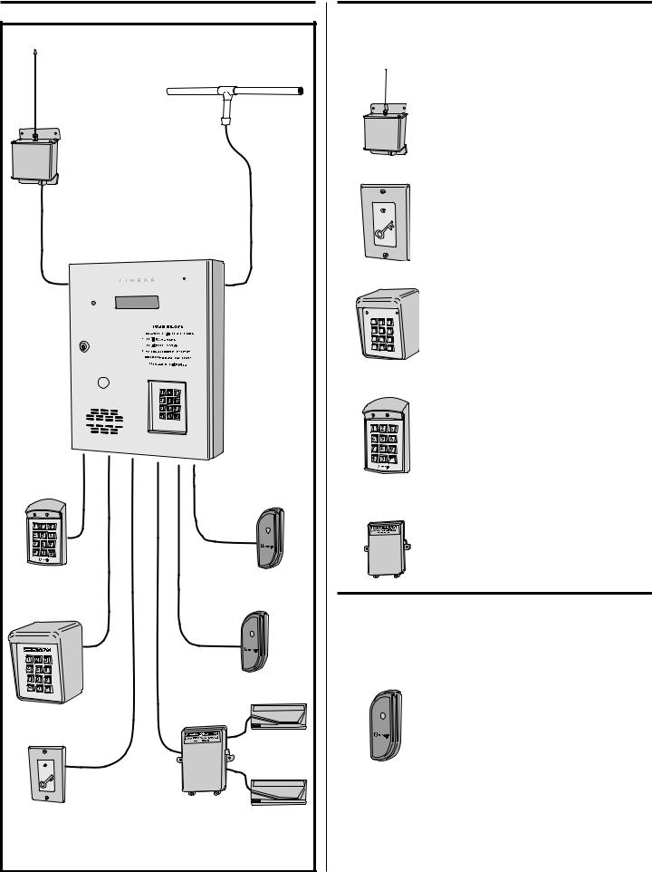
Accessory Overview |
|
PBUS Accessories |
||||
|
|
Several compatible accessories are available to connect to the three |
||||
|
|
6-wire communications “PBUS” inputs. Up to six PBUS accessories can |
||||
|
|
be used with each AE1000Plus unit. |
||||
|
|
|
|
|
AM-RRR Remote Radio Receiver |
|
|
|
|
|
|
For wireless transmitters, connect the Model |
|
|
EXA-2000 |
|
|
|
AM-RRR high-gain superheterodyne UHF receiver. |
|
|
|
|
|
The receiver is housed in a weather-resistant |
||
|
REMOTE |
|
|
|
enclosure and can be mounted indoors or |
|
|
RADIO |
|
|
|
||
AM-RRR |
|
|
|
outdoors. Gaskets and a weather-tight wiring strain |
||
ANTENNA |
|
|
|
|||
REMOTE |
|
|
|
|
relief seal the unit from the elements. |
|
RADIO |
|
AM-RRR |
|
AM-RPR Radio Proximity Receiver |
||
RECEIVER |
|
|
||||
|
|
|
|
The Model AM-RPR functions as a remote device |
||
|
|
|
|
|
||
|
|
|
|
|
that supplies localized radio reception for the |
|
|
|
|
|
|
AE1000Plus In a typical installation, the AM-RPR |
|
AE1000Plus |
|
|
|
|
would be mounted in a plastic single-gang electrical |
|
TELEPHONE ENTRY |
|
|
|
|
box next to the controlled opening. When the user |
|
& ACCESS CONTROL |
|
|
|
|
requires access, their transmitter must be activated |
|
SYSTEM |
|
|
|
|
within three inches of the AM-RPR faceplate. |
|
|
|
AM-RPR |
AM-KP Exterior Keypad |
|||
|
|
|
|
|
The Model AM-KP is housed in a rugged cast |
|
|
|
|
|
|
aluminum enclosure designed for exterior |
|
|
|
|
|
|
installations. The die-cast keys have bright, |
|
|
|
1 |
2 |
3 |
easy-to-read yellow graphics. The keypad can |
|
|
|
4 |
5 |
6 |
||
|
|
be mounted to a pedestal or directly to a wall. |
||||
|
|
7 |
8 |
9 |
||
|
|
* |
0 |
# |
A keylock secures the keypad to the mounting |
|
|
|
AM-KP |
backplate. |
|||
|
|
|
|
|
AM-KPI Interior Keypad |
|
|
|
|
|
|
The Model AM-KPI keypad is housed in a rugged, |
|
|
|
|
|
|
plastic enclosure designed to be mounted indoors |
|
|
|
|
|
|
in a standard single-gang electrical box. Tamper |
|
|
|
|
|
|
resistant screws secure the keypad to its mounting |
|
|
|
|
|
|
plate. The die-cast keys have bright, easy-to-read |
|
|
|
|
|
|
yellow graphics and is illuminated with white |
|
PBUS |
WIEGAND |
|
|
|
LEDs. The keypad is supplied with a satin-chrome |
|
AM-KPI |
bezel and three interchangeable colored bezels |
|||||
ACCESSORIES |
||||||
ACCESSORIES |
|
|
|
(white, ivory, & bronze) to customize the keypad |
||
|
|
|
|
|||
|
|
|
|
|
||
|
|
|
|
|
appearance for the installation. |
|
|
|
|
|
|
AM-CRI Card Reader Interface |
|
|
|
|
|
|
The Model AM-CRI expands the standard two |
|
|
|
|
|
|
AE1000Plus Wiegand inputs by supporting one |
|
AM-KPI |
|
|
|
|
or two additional 26-bit Wiegand input devices per |
|
INTERIOR |
AM-PR |
|
|
AM-CRI |
AM-CRI interface used. |
|
KEYPAD |
PROXIMITY |
Wiegand Accessories |
||||
|
READERS |
|||||
|
|
The two WIEGAND format inputs connect WIEGAND devices to the |
||||
|
|
AE1000Plus. Linear offers a Wiegand format proximity reader. Most other |
||||
|
|
manufacturer’s 26, 30 & 31-bit WIEGAND output devices can also be |
||||
|
|
used with the AE1000Plus. |
||||
|
|
|
|
|
AM-PR Proximity Reader |
|
AM-KP |
|
|
|
|
The Model AM-PR is a radio-based reader that |
|
|
|
|
|
works with either proximity tags (Model AM-PT) or |
||
EXTERIOR |
|
|
|
|
proximity cards (Model AM-PC), both of which are |
|
KEYPAD |
|
|
|
|
||
|
|
|
|
slotted to attach to key rings. Upon reading a user’s |
||
|
|
|
|
|
||
|
WIEGAND |
|
|
|
tag or card, the reader sends the entry data via a |
|
|
CARD |
|
|
AM-PR |
Wiegand output to the AE1000Plus. An integral |
|
|
READERS |
|
|
|
LED confi rms to the user that access is granted. |
|
AM-RPR |
|
|
|
|
|
|
RADIO |
AM-CRI |
|
|
|
|
|
PROXIMITY |
CARD |
|
|
|
|
|
RECEIVER |
READER |
|
|
|
|
|
INTERFACE |
|
|
|
|
||
4 |
|
|
|
|
|
|

Component Locations
OPTIONAL
CAMERA 
CABINET
LOCK
OPTIONAL
POSTAL
LOCK
SPEAKER
INSTALLATION NOTE:
FOR EASY WIRING, THE UNIT'S TERMINAL BLOCKS CAN BE UN-PLUGGED FROM THE CIRCUIT BOARD
KEYPAD LIGHTING
MICROPHONE
DISPLAY
KEYPAD
|
|
RECEIVER |
TAMPER |
|
|
|
CAMERA |
|
RANGE KNOB |
SWITCH |
MICROPHONE |
TAMPER |
|
|
|
CONNECTOR |
MAGNET |
|||
CONNECTOR |
CPU/INTERFACE |
ANTENNA |
|
DISPLAY |
|
|
TAMPER |
|
CONNECTOR |
CONNECTOR |
|
OPTIONAL |
|
SWITCH |
|
|
|
|
||
|
|
|
|
|
CAMERA |
|
|
|
|
|
|
|
|
VIDEO |
|
|
|
|
|
DISPLAY |
CONNECTOR |
|
|
|
|
|
|
|
|
|
|
|
CONTRAST |
|
|
|
|
|
|
|
|
WIEGAND |
|
|
|
|
|
ADJUSTMENT |
|
|
|
|
RELAY |
|
|
INPUT |
|
|
|
|
|
|
TERMINALS |
|
|
|
|
TERMINALS |
|
|
|
|
|
|
|
SPEAKER |
|
|
|
|
|
SYSTEM |
VOLUME |
PBUS |
|
|
|
|
ADJUSTMENT |
|
|
|
|
|
RESTART |
||
TERMINALS |
|
|
|
|
|
|
|
|
|
|
BUTTON |
|
|
|
|
|
|
|
|
|
NETWORK |
|
|
|
|
|
POSTAL LOCK |
TERMINALS |
|
|
|
|
|
|
|
|
|
|
MOUNTING PLATE |
||
|
|
|
|
|
||
AM-MIO |
|
|
|
|
SPEAKER |
|
INTERFACE |
|
RS-232 |
|
|
|
|
TELEPHONE |
|
POWER |
|
|
|
|
|
PORT |
EARTH |
|
|
||
INTERFACE |
TELEPHONE |
TERMINALS |
PROCESSOR MODULE |
|||
CONNECTOR |
|
JACK |
|
GROUND |
POWER CONNECTOR |
|
|
MAIN POWER |
STUD |
||||
TELEPHONE |
|
|
|
|||
|
SWITCH |
|
|
|
||
TERMINALS |
|
|
|
|
|
|
|
|
|
|
|
|
|
5
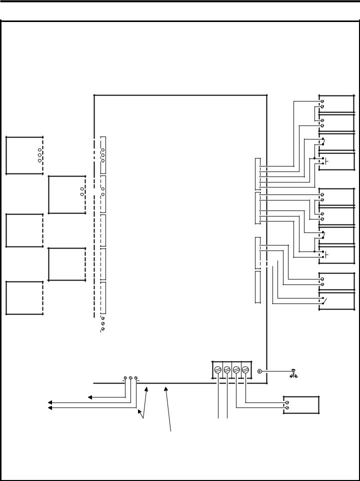
Wiring Diagram
THIS WIRING EXAMPLE SHOWS:
DOOR ACCESS WITH A DOOR STRIKE ON RELAY CHANNEL "A" DOOR ACCESS WITH A MAGNETIC LOCK ON RELAY CHANNEL "B" GATE ACCESS WITH A GATE OPERATOR ON RELAY CHANNEL "C" (YOUR INSTALLATION MAY VARY)
LED2

 LED2 HOLD
 HOLD
HOLD
LED1 

 LED1 WIEGAND DAT 1

 DAT 1
DAT 1
DEVICE
DAT 0 

 DAT 0 GND
 GND PWR
 PWR
PWR
LED2

 LED2
LED2
HOLD

 HOLD
HOLD
LED1 

 LED1
LED1
WIEGAND DAT 1 

 DAT 1
DAT 1
DEVICE
DAT 0

 DAT 0
DAT 0
GND

 GND
GND
PWR

 PWR
PWR
PWR

 PWR GND

 GND PBUS DAT1

 DAT1
DAT1
DEVICE DAT0

 DAT0 DVAL

 DVAL PCLK

 PCLK
PCLK
PWR

 PWR
PWR
GND

 GND
GND
PBUS DAT1

 DAT1
DAT1
DEVICE DAT0

 DAT0
DAT0
DVAL

 DVAL
DVAL
PCLK

 PCLK
PCLK
PWR

 PWR GND

 GND PBUS DAT1

 DAT1
DAT1
DEVICE DAT0

 DAT0 DVAL

 DVAL PCLK

 PCLK
PCLK
|
|
|
|
|
|
|
|
|
|
|
|
|
|
|
|
NET-B |
|
|
|
|
|
|
|
|
|
|
|
|
|
|
|
|
|
GND |
|
|
|
|
|
|
|
|
|
|
|
|
|
|
|
|
|
NET-A |
|
NETWORK |
|
NETWORK |
|
NETWORK |
|
|
|
|
|
|
|
|
|
|
|
|
|
|
|
|
|
|
|
|
|
|
|
|
|
|
|
||||
UNIT |
|
|
UNIT |
|
UNIT |
|
|
|
|
|
|
|
|
AM-MIO |
|
||
|
|
|
|
|
|
|
|
|
|
|
|
|
INTERFACE |
|
|||
|
|
|
|
|
|
|
|
|
|
|
|
|
|
|
|
|
|
|
|
|
|
|
|
|
|
|
|
|
|
|
|
|
|
|
|
MULTIPLE NETWORK UNITS |
|
|
|
|
|
|
|
|
|
|
|
|
|||||
REFER TO NETWORK SECTION |
|
|
|
|
|
|
|
|
TELEPHONE |
||||||||
|
FOR WIRING OPTIONS |
|
|
|
|
|
|
|
|
TERMINALS |
|||||||
|
|
|
|
|
|
|
|
|
|
|
|
|
|
||||
|
|
|
|
|
|
|
|
|
|
|
|
|
|
|
|
|
|
|
|
|
|
|
|
EARTH |
|||||||||||
|
|
|
|
|
|
GROUND |
|||||||||||
|
TO DEDICATED |
|
|
|
|
|
|
|
|
|
|
|
|
|
|
||
TELEPHONE LINE |
|
|
|
|
|
|
|
|
|
|
|
|
|
|
|||
AE1000Plus
READER A
TERMINALS
READER B
TERMINALS
PBUS "A"
TERMINALS
PBUS "B"
TERMINALS
PBUS "C"
TERMINALS
NETWORK
TERMINALS
GND |
|
|
|
|
TELEPHONE |
RS-232 |
||||
THREA |
TIP GINR |
|
JACK |
PORT |
||||||
|
|
|||||||||
|
|
|
|
|
|
|
|
|
||
|
|
|
|
|
|
|
|
|
|
|
|
|
|
|
|
|
|
|
|
|
|
|
|
|
|
|
|
|
|
|
|
|
|
|
|
|
|
|
|
|
|
|
|
RELAY
CHANNEL "A"
TERMINALS
RELAY
CHANNEL "B"
TERMINALS
RELAY RATING: 3 AMPS @ 30 VOLTS AC/DC MAXIMUM
RELAY
CHANNEL "C"
TERMINALS
RELAY
CHANNEL "D"
TERMINALS
N.C. 
COM 
N.O. 
DS-A 
GND 
RTE-A 
N.C. 
COM 
N.O. 
DS-B 
GND 
RTE-B 
N.C. 
COM 
N.O. 
DS-C 
GND 
RTE-C 
N.C. 
COM 
N.O. 
DS-D 
GND 
RTE-D 
POWER |
|
|
TERMINALS |
|
|
12-24 VOLTS AC/DC |
|
|
DC + DC - AC |
AC |
GROUND |
|
|
|
|
|
STUD |
EARTH
GROUND
STAKE
16 VAC
35 VA
TRANSFORMER
CONNECT TELEPHONE LINE TO |
|
|
|
|
|
|
|
|
12 VOLT |
||||||
TERMINALS OR TELEPHONE JACK |
|
||||||
BATTERY |
|||||||
|
|||||||
ELECTRIC
DOOR
STRIKE
DOOR
STRIKE
POWER SUPPLY
DOOR
SENSE
CONTACT
DOOR EXIT
REQUEST
BUTTON
MAGNETIC
DOOR
LOCK
DOOR
LOCK
POWER SUPPLY
DOOR
SENSE
CONTACT
DOOR EXIT
REQUEST
BUTTON
OPEN |
OPERATOR |
|
GATE |
GATE
EXIT LOOP
SENSOR
FOR LOCAL COMPUTER CONNECTION |
NOTE: OPTIONAL |
USE LINEAR MODEL A2C |
BACKUP BATTERY |
SERIAL COMPUTER CABLE |
WILL REQUIRE AN |
|
EXTERNAL CHARGER |
6
Important Mounting Requirements
The AE1000Plus Telephone Entry System can be installed for public or private use. The mounting requirements will vary depending on the installation. Review the following information before beginning the installation.
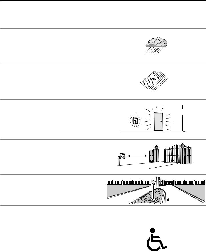
Mounting Environment
Consider the environmental factors at the desired mounting location. The AE1000Plus is designed for direct outdoor installations, however, it is preferable to protect the unit from extreme exposure to sun, driving rain, or snow whenever possible. Mounting the unit in a kiosk can provide extra environmental protection.
Follow Building Codes
Check all local building codes and ordinances prior to installing the |
? |
|
system. Proper installation of the AE1000Plus conforming to the local |
||
? |
||
building codes for access control equipment is a regulatory requirement. |
||
|
||
The AE1000Plus installation is an extremely important and integral part |
? |
|
of the overall access control system. |
Mounting Location
If the AE1000Plus is used to control a door or pedestrian gate, locate the unit as near as practical to the entry point. If the unit is mounted on or in a wall adjacent to the entry point, be sure the wall is sturdy. The repeated shock and vibration from a slamming access door or springloaded pedestrian gate must be isolated from the AE1000Plus. NEVER
MOUNT THE UNIT DIRECTLY TO A MOVING DOOR OR GATE!
Gate Installations
If the AE1000Plus is used to control a gate operator connected to a |
|
vehicular gate, the unit MUST be mounted AT LEAST 10 feet away from |
|
the gate (open and closed) and gate operator. AT NO TIME SHOULD A |
10 FEET |
PERSON BE ABLE TO TOUCH THE GATE OR GATE OPERATOR AND |
MINIMUM |
|
|
THE AE1000Plus AT THE SAME TIME. |
|
Vehicle Traffic
Do not mount the AE1000Plus where it extends into any traffi c lane.Locate the gooseneck pedestal or entry kiosk so all parts of the AE1000Plus are outside the traffi c lane. Locate the AE1000Plus clear of any turn-around lanes vehicles use when access is denied.
Americans with Disability Act (A.D.A.) Requirements
THE FOLLOWING WHEELCHAIR ACCESS REQUIREMENTS ARE
FOR PUBLIC DOOR CONTROL INSTALLATIONS ONLY.
1.If the clear fl oor space allows only forward approach to the system, the maximum high forward reach allowed is 48” above grade to the top of the keypad.
2.If the high forward reach to the system is over an obstruction of greater than 20” but less than 25”, the maximum high forward reach allowed is 44” above grade to the top of the keypad.
3. If the clear fl oor space allows parallel approach by a person in a wheelchair, the maximum high side reach shall be 54” above grade to the top of the keypad.
4.If the high side reach is over an obstruction of 24” or less, the maximum high side reach allowed is 46” above grade to the top of the keypad.
?
?
?

 !
!
 EDGE OF TRAFFIC LANE
7
Entry System Mounting
The AE1000Plus cabinet is designed to be mounted three ways:
•The unit can be mounted directly to a wall or fl at surface.
•The unit can be mounted recessed into the wall.
•The unit can be mounted on a standard gooseneck pedestal. Choose a well lit location near the controlled opening. Wiring access for power, telephone, earth ground, control output must be available to the mounting location. If the optional remote accessories are used, wiring access for these cables must also be available to the mounting location.
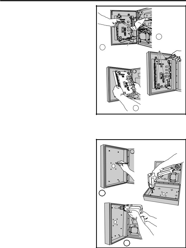
Mounting Preparation
Before mounting the system, the main circuit board mounting plate must be removed to provide access for the wiring hole and mounting fasteners.
CAUTION!: Touch a grounded object before proceeding to discharge static electricity from your body.
1.Carefully remove the four main circuit board wiring connectors:
• The CPU/interface ribbon cable connector.
• The processor module power connector.
• The telephone interface connector.
• The tamper switch connector.
2.Remove the nut from the Earth Ground stud and remove the green ground wire lug from the stud.
3.Remove the two bottom circuit board mounting plate nuts.
4.Loosen the two top circuit board mounting plate nuts.
5.Carefully lift up on the mounting plate, removing the circuit board mounting plate. Set it aside in a safe place.
Reverse these steps to replace the circuit board mounting plate after the cabinet mounting is complete.
1 |
GROUND WIRE STUD |
CAREFULLY REMOVE THE FOUR WIRING HARNESS CONNECTORS & GROUND WIRE
MOUNTING
PREPARATION
2
LOOSEN THE TOP TWO NUTS & REMOVE
THE BOTTOM TWO NUTS
3CAREFULLY REMOVE THE CIRCUIT BOARD
Surface Mounting
The cabinet can be mounted on a wall or any suitable fl at surface. The four 3/8” mounting holes or the four self-drill locations can be used to attach the cabinet to the surface.
1.For wall mounting, hold the cabinet at the approximate mounting location where the display will be about eye level or slightly above.
2A. If using the 3/8” mounting holes, mark the four mounting hole centers. Drill as required. Use the appropriate fasteners for the mounting surface to secure the cabinet.
2B. If using the self-drill mounting holes, choose the correct size bit for the fasteners and drill the cabinet as required. Use the appropriate fasteners for the mounting surface to secure the cabinet.
3.After routing the wiring into the cabinet, replace the circuit board mounting plate and plug in the wiring connectors. Be sure to replace the green ground wire.
SURFACE
MOUNTING
OR
1 MARK THE FOUR MOUNTING HOLES
DRILL THE CABINET AT THE
PRE-MARKED LOCATIONS
2 |
ATTACH THE CABINET WITH APPROPRIATE |
|
HARDWARE FOR THE MOUNTING SURFACE |
8
 Loading...