


AE-500
Telephone Entry
& Access Control
System
Facility Manager’s Guide
USA & Canada (800) 421-1587 & (800) 392-0123
(760) 438-7000 - Toll Free FAX (800) 468-1340
www.linearcorp.com

Contents |
|
Contents......................................................................................... |
2 |
Introduction .................................................................................... |
2 |
Operation........................................................................................ |
2 |
Database Overview ......................................................................... |
2 |
System Features............................................................................. |
3 |
Programming with a Computer ....................................................... |
4 |
Setting up Multiple Units................................................................. |
5 |
Programming Over the Telephone ................................................... |
6 |
Programming from the Local Keypad............................................... |
6 |
Programming Reference.................................................................. |
7 |
Factory Settings ............................................................................. |
7 |
Programming Notes ........................................................................ |
7 |
Resident Data Programming ........................................................... |
8 |
Entry Code Programming ................................................................ |
9 |
Wireless Transmitter Programming ............................................... |
10 |
Wireless Transmitter Programming (Continued) ............................. |
11 |
System Options ............................................................................. |
12 |
System Options (Continued) .......................................................... |
13 |
System Utilities.............................................................................. |
14 |
AE-500 Operation........................................................................... |
15 |
Troubleshooting ............................................................................ |
16 |
Linear Limited Warranty................................................................ |
16 |
Introduction
The Model AE-500 Telephone Entry & Access Control System is designed for use as a primary access control device for gated communities, parking garages, offi ce buildings, apartments, dormitories, hotels/motels, commercial buildings and recreational facilities with up to 250 residents or users.
Housed in a locked, rugged stainless steel faced enclosure, the AE-500 features a side-lit 12-key telephone style keypad with bright, easy-to- read graphics, a backlit two-line directory display with a programmable welcome message, a built-in microphone, and speaker.
The two relay output channels can be programmed to control electric door strikes, magnetic locks, door & gate operators, or barrier gates. The system utilizes hands-free, full duplex telephone communications between visitors and residents for granting access.
The system can be programmed locally using the keypad, remotely with a touch tone telephone, or remotely using a computer equipped with a modem and a web browser.
Operation
In a typical installation, the unit’s memory would be programmed with each resident’s name and directory code number. Arriving visitors would use the keypad on the AE-500 to view the directory names and directory number for the desired resident. Upon entering the directory number, the AE-500 will automatically dial the resident’s telephone number and establish two-way voice communication between the visitor and the resident. The resident will then have the option to grant or deny access to the visitor by pressing a digit on their telephone.
In addition to the telephone entry, the AE-500 can grant access using entry codes (up to 500 entry codes) at the local or remote keypad. Block coded and single enrolled MegaCode® transmitters (up to a total of 1000 transmitters) can be used to gain access through the AE-500’s built-in radio receiver. Each transmitter can be individually deactivated or reactivated. In addition, a single enrolled transmitter can be deleted.
Database Overview
Programming the AE-500 involves entering installation information into the system’s memory. The system uses this information as a reference “database” to control the operation of the system.
Resident Data
Up to 250 resident names and telephone numbers can be set.Each resident entry is assigned a directory number. Directory numbers can be from two to four digits in length (all will be the same length).The directory number is the number a visitor would enter to have the system call the resident.
RESIDENT DATA (UP TO 250 RESIDENTS)
FOR EACH RESIDENT: DIRECTORY NUMBER (2 TO 4 DIGITS)
NAME (UP TO 16 CHARACTERS)
PHONE # (UP TO 12 DIGITS)
Entry Code Data
An entry code is a number entered at the AE-500 keypad or remote keypad to request access. Up to 500 entry codes can be set. Entry codes can be from two to six digits in length (all will be the same length).
Entry codes can be programmed for timed or toggle operation. Timed relays activate for a programmed length of time.Toggle relays latch on until the next time a toggle entry code is entered, then the relay unlatches. Each entry code can also be set for a limited or unlimited number of uses.
An entry code will activate Relay Channel “A” or “B” depending on how the entry code is programmed and whether or not a remote keypad is attached:
•When an entry code is programmed to activate a specifi c relay, the selected relay will activate when the code is entered on either the AE-500 keypad or the remote keypad.
•When an entry code is programmed to activate both relays, and a remote keypad is attached, Relay Channel “A” will activate if the entry code is entered on the AE-500 keypad; Relay Channel “B” will activate if the entry code is entered on the remote keypad.
•When an entry code is programmed to activate both relays, and a remote keypad is not attached, the entry code will activate both Relay Channels “A” and “B”.
When an entry code is programmed to activate both relays, only timed relay mode is available for that code, toggle relay mode is unavailable.
ENTRY CODE DATA (UP TO 500 CODES)
FOR EACH CODE: ENTRY CODE (2 TO 6 DIGITS)
RELAY SELECTOR
TEMPORARY USAGE COUNT
Transmitter Data
Up to 1000 wireless transmitters can be used with the system. Up to 500 transmitters can be ordered in pre-programmed blocks of sequential ID codes. Up to 16 blocks of transmitters can be used. Another option is to utilize up to 500 transmitters that are singly assigned. A transmitter will activate either relay output depending the button programming (same for all transmitters in the system). An individual transmitter can be deactivated in case it is lost or stolen. A single enrolled transmitter can also be deleted.
TRANSMITTER DATA (UP TO 1000 TRANSMITTERS)
FOR EACH TRANSMITTER: TRANSMITTER ID # (1-65535)
OPTIONAL FACILITY CODE (0-15)
2
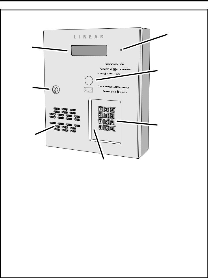
System Features
MICROPHONE
DISPLAY
OPTIONAL
POSTAL


 LOCK CABINET

LOCK
KEYPAD
SPEAKER
KEYPAD
LIGHTING
Your access control installation company has set this master password for this installation:
_______________________
Use this password to enter programming mode.
3

Programming with a Computer
The AE-500’s built-in programming interface can be accessed on-site (using a separate telephone line) or off-site using a computer with a modem and any Internet browser (if using Netscape, be sure Java is installed). The AE-500 can be programmed using the local keypad or with a telephone, but computer programming is the easiest method.
Navigating through the AE-500’s programming “pages” is similar to browsing through your favorite web site’s pages. Anyone familiar with
the Internet will fi nd programming the AE-500 with a computer very easy. The AE-500’s memory contains the “pages” that the computer will view. When selections and changes are made on the computer, the AE-500’s memory is programmed to your custom settings.
The following screen pictures show setting up a “Dial-up” connection in Windows™ XP and how to connect with a single AE-500. To create “Dialup” connections for multi-unit installations, see the next page.
4

Setting up Multiple Units
The system supports up to seven AE-500s connected to the same telephone line.
Some telephone systems may only support up to four units on the same telephone line. In multiple-unit installations each AE-500 must be assigned a unique unit number before programming. The unit number allows connecting to a specifi c unit when calling for programming. One unit must be assigned as Unit #1.
NOTE: If this is a multi-unit installation, the installation company most likely has already set the unit numbers. The following programming step is shown for reference.
To set a unit’s number perform the following steps on each AE-500 unit connected to the same telephone line.
1.If not already in Programming Mode, use the local keypad to enter the master password and access programming.
2.Press: 


3. Enter the unit number (1-7).
4.Press 
5.Exit Programming Mode.
Multiple Unit Installation Programming Information
To computer program multi-unit installations that use the same telephone line, each unit will require a separate “Dial-up” connection.
Creating a Connection for Each Unit
1.Start creating a “Dial-up” connections for each unit as described on Page 13.
2.When the “New Connection Wizard” asks for the “Connection Name”
(Step #6 in the Page 13 fi gure) enter a unique name for the specifi c unit.
Example: “AE-500 Unit #2”
3. When the “New Connection Wizard” asks for the “Phone Number to Dial” (Step # 7 in the Page 13 figure) enter the common telephone number for the multi-unit installation followed by four commas, the unit number, and a #.
Example: “555-1234,,,,2#”
NOTE: Each comma adds a 2-second delay to the dialing process. Depending on the time required by the telephone system to make a connection to the AE-500, more or less commas might be required.
4. When the “New Connection Wizard” is fi nished, a desktop icon named for each AE-500 unit will be created on the computer.
To connect to a specifi c unit for programming, double-click on the desktop icon named for the unit.
Copying Data from One Unit to Another
If multiple units will be sharing the same programming information, data from one unit can be copied to another. A backup fi le is created in this process to make copies. For security, backing up a unit’s data is always a good idea.
1.After entering the Resident Data, Media Data, and programming options for the fi rst unit, click “Utilities”, then “Data Backup”. Click “Save” at the XML warning window then select a fi le to save to.
2.After the data backup is complete, disconnect from the fi rst unit, then reconnect to the unit to copy the data to.
3. From the home page, click “Utilities”, then “Load Factory Defaults”. When complete, click “Data Restore” and browse for the fi le to copy. Select the
fi le and click “Upload” to send the fi le to the unit.
IMPORTANT NOTE: Always load the factory defaults into a unit before performing data restore. Otherwise, the unit’s data may become corrupted.
4. Make any other unit-specifi c programming changes before disconnecting.
SETTING A UNIT NUMBER |
PPN 71 |
71#UNIT#
UNIT = UNIT NUMBER (1-7) FOR MULTI-UNIT INSTALLATION
FACTORY SETTING: UNIT NUMBER 1
5
 Loading...