Linear 212LS-C26DCR-LT User Manual

Features
Simple to Install -The DoorGard 212LS Lockset installs in 15 minutes and programs the same as all DoorGard/IEI keypads. It includes all mounting hardware, and easily retrofits into any standard cylindrical door prep (ANSI/BHMA A 156.2-2003). The 212LS has a replaceable core, for the manual key override. The sleek design fits with any décor and is available in 26D Stainless and US3 Polished Brass, right or left handed crescent door handles.
Right Hand
212LS – C26DCR-Rt - F/G:DoorGard Grade 2 Lockset/Cylindrical, Stainless, Crescent handle, Right handed.
212LS – CUS3CR-Rt - F/G: DoorGard Grade 2 Lockset/Cylindrical, Stainless, Crescent handle, Right handed.
Left Hand
212LS – C26DCR-Lt - F/G: DoorGard Grade 2 Lockset Cylindrical, Stainless, Crescent handle, Left handed.
212LS – CUS3CR-Lt - F/G: DoorGard Grade 2 Lockset Cylindrical, Stainless, Crescent handle, Left handed.
Easy to Maintain -Change the battery in three minutes. The 212LS Lockset uses four (4) 1.5V AA batteries for up to 15,000 uses or up to five years. An alarm activates Low Battery Alert allowing for 30 more uses.
User Codes - The 212LS lock recognizes up to 120 users with a different code for each, and the lockset retains codes without batteries. Codes can be one to six digits in length and digits can be repeated. The Master Code is always stored in user location one (1). A reset button is provided inside the lock which restores factory defaults and removes codes already stored. The lockset is equipped with an override mechanical key. The code toggles to allow passage for an event so any key will open the lock.
Security and Protection -The 212LS Lockset is designed with a safeguard against forced entry since the outside lever is not mechanically connected to the latch until the lock activates. Also, after three invalid code attempts, there is a 20 second lockout period for the keypad.
Rugged Design -The 212LS is designed for both commercial and industrial use.
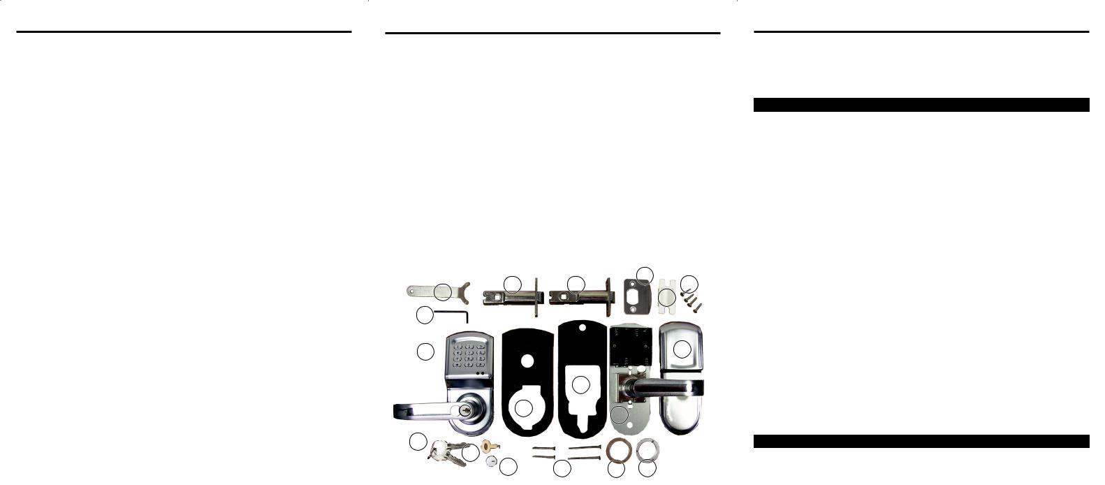
Lockset Parts List
1. |
Spanner wrench |
11. |
Interior Faceplate/Door |
2. |
T-Strike Door Latch |
|
Handle w/battery case |
|
2-3/8” Backset |
12. |
Interior Faceplate |
3. |
T-Strike Door Latch |
13. |
Override Keys (2) |
|
2-3/4” Backset |
14. |
Pin Wrench (pries open key |
4. |
Strike Plate |
|
slot cover) |
5. |
Strike Plate Cover |
15. |
Key Slot Cover |
6. |
Latch/Strikeplate Screws |
16. |
Screws: 2 sets Lock |
7. |
Allen Wrench |
|
Assembly screws (thick, |
8. |
Exterior Door Handle/ |
|
thin doors) |
|
keypad |
17. |
Sealing Washer |
9. |
Exterior Gasket |
18. |
Faceplate Assembly Nut |
10. |
Interior Gasket |
|
|
|
|
|
4 |
1 |
2 |
3 |
6 |
|
|
5 |
|
|
|
|
|
7 |
|
|
|
8 |
|
|
12 |
|
|
10 |
|
9 |
11 |
|
13
14
15 |
16 |
17 |
18 |
Figure 1. Parts Diagram
Installation Steps
Door & Frame Prep
•Remove existing Lock from door
•If it is new door with no holes, use template provided
•Measure backset.
Installation
1.Unpack the lockset and inventory all parts. Remove mounting screws, separate lock assembly, and both interior/exterior handle plates and the two rubber gaskets.
2.Insert the strike plate hole cover (#5) and attach strike plate (#4) in the door jam/frame, securing with two Phillips head screws.
3.Install T-Strike Door Latch (#2 or #3) into doorjam/frame and secure with two Phillips head screws.
4.Assemble locks inserting two Rubber Gaskets (#8, 9, 10, 11).
5.Thread battery wires through hole in Interior Faceplate/Door
Handle (#11).
6.Attach Interior Faceplate/Door Handle (#11) to Exterior Door
Handle (#8), securing with two short or long assembly screws. (#16)
7.Insert batteries and connect battery clip.
8.Secure Interior Faceplate (#12) with clear plastic washer with Nut (#17, 18)
9.Use spanner wrench (#1) to tighten nut (#15).
10.Program the system as described in this manual.
11.Instruct the users on lockset operation.
Manual Operation
•Use Pin Wrench (#14) to pull off cover (#15).
•Use override key (#13).
•Turn left twice.
P1345
 Loading...