


RETURN TO MAIN MENU
IM539
Synergic 7F and Synergic 7FH |
October, 1999 |
|
|
|
|
Semiautomatic Wire Feeders or Controls with code numbers 10189, 10190 & 10191 |
|
Safety Depends on You
Lincoln arc welding and cutting equipment is designed and built with safety in mind. However, your overall safety can be increased by proper installation ... and thoughtful operation on your part.
DO NOT INSTALL, OPERATE OR REPAIR THIS EQUIPMENT WITHOUT READING THIS MANUAL AND THE SAFETY PRECAUTIONS CONTAINED THROUGHOUT. And, most importantly, think before you act and be careful.
OPERATOR’S MANUAL
•World's Leader in Welding and Cutting Products •
•Sales and Service through Subsidiaries and Distributors Worldwide •
Cleveland, Ohio 44117-1199 U.S.A. TEL: 216.481.8100 FAX: 216.486.1751 WEB SITE: www.lincolnelectric.com
WARNING
ARC WELDING can be hazardous.
PROTECT YOURSELF AND OTHERS FROM POSSIBLE SERIOUS INJURY OR DEATH. KEEP CHILDREN AWAY. PACEMAKER WEARERS SHOULD CONSULT WITH THEIR DOCTOR BEFORE OPERATING.
Read and understand the following safety highlights. For additional safety information it is strongly recommended that you purchase a copy of “Safety in Welding & Cutting - ANSI Standard Z49.1” from the American Welding Society, P.O. Box 351040, Miami, Florida 33135 or CSA Standard W117.2-1974. A Free copy of “Arc Welding Safety” booklet E205 is available from the Lincoln Electric Company, 22801 St. Clair Avenue, Cleveland, Ohio 44117-1199.
BE SURE THAT ALL INSTALLATION, OPERATION, MAINTENANCE, AND REPAIR PROCEDURES ARE PERFORMED ONLY BY QUALIFIED INDIVIDUALS.
ELECTRIC SHOCK can
kill.
1.a. The electrode and work (or ground) circuits are electrically “hot” when the welder is on.
Do not touch these “hot” parts with your bare skin or wet clothing. Wear dry, hole-free gloves to insulate hands.
1.b. Insulate yourself from work and ground using dry insulation. Make certain the insulation is large enough to cover your full area of physical contact with work and ground.
In addition to the normal safety precautions, if welding must be performed under electrically hazardous conditions (in damp locations or while wearing wet clothing; on metal structures such as floors, gratings or scaffolds; when in cramped positions such as sitting, kneeling or lying, if there is a high risk of unavoidable or accidental contact with the workpiece or ground) use the following equipment:
•Semiautomatic DC Constant Voltage (Wire) Welder.
•DC Manual (Stick) Welder.
•AC Welder with Reduced Voltage Control.
1.c. In semiautomatic or automatic wire welding, the electrode, electrode reel, welding head, nozzle or semiautomatic welding gun are also electrically“hot”.
1.d. Always be sure the work cable makes a good electrical connection with the metal being welded. The connection should be as close as possible to the area being welded.
1.e. Ground the work or metal to be welded to a good electrical (earth) ground.
1.f. Maintain the electrode holder, work clamp, welding cable and welding machine in good, safe operating condition. Replace damaged insulation.
1.g. Never dip the electrode in water for cooling.
1.h. Never simultaneously touch electrically “hot” parts of electrode holders connected to two welders because voltage between the two can be the total of the open circuit voltage of both welders.
1.i. When working above floor level, use a safety belt to protect yourself from a fall should you get a shock.
1.j. Also see Items 4.c. and 6.
ARC RAYS can burn.
2.a. Use a shield with the proper filter and cover plates to protect your eyes from sparks and the rays of the arc when welding or observing open arc welding. Headshield and filter lens should conform to ANSI Z87. I standards.
2.b. Use suitable clothing made from durable flame-resistant material to protect your skin and that of your helpers from the arc rays.
2.c. Protect other nearby personnel with suitable non-flammable screening and/or warn them not to watch the arc nor expose themselves to the arc rays or to hot spatter or metal.
FUMES AND GASES can be dangerous.
3.a. Welding may produce fumes and gases hazardous to health. Avoid breathing these fumes and gases.When welding, keep your head out of the fume. Use enough ventilation and/or exhaust at the arc to keep
fumes and gases away from the breathing zone. When welding with electrodes which require special ventilation such as stainless or hard facing (see instructions on container or MSDS) or on lead or cadmium plated steel and other metals or coatings which produce highly toxic fumes, keep exposure as low as possible and below Threshold Limit Values (TLV) using local exhaust or mechanical ventilation. In confined spaces or in some circumstances, outdoors, a respirator may be required. Additional precautions are also required when welding on galvanized steel.
3.b. Do not weld in locations near chlorinated hydrocarbon vapors coming from degreasing, cleaning or spraying operations. The heat and rays of the arc can react with solvent vapors to form phosgene, a highly toxic gas, and other irritating products.
3.c. Shielding gases used for arc welding can displace air and cause injury or death. Always use enough ventilation, especially in confined areas, to insure breathing air is safe.
3.d. Read and understand the manufacturer’s instructions for this equipment and the consumables to be used, including the material safety data sheet (MSDS) and follow your employer’s safety practices. MSDS forms are available from your welding distributor or from the manufacturer.
3.e. Also see item 7b.

 WELDING SPARKS can
 cause fire or explosion.
4.a..Remove fire hazards from the welding area. If this is not possible, cover them to prevent the welding sparks from starting a fire.
Remember that welding sparks and hot materials from welding can easily go through small cracks and openings to adjacent areas. Avoid welding near hydraulic lines. Have a fire extinguisher readily available.
4.b. Where compressed gases are to be used at the job site, special precautions should be used to prevent hazardous situations. Refer to “Safety in Welding and Cutting” (ANSI Standard Z49.1) and the operating information for the equipment being used.
4.c. When not welding, make certain no part of the electrode circuit is touching the work or ground. Accidental contact can cause overheating and create a fire hazard.
4.d. Do not heat, cut or weld tanks, drums or containers until the proper steps have been taken to insure that such procedures will not cause flammable or toxic vapors from substances inside. They can cause an explosion even though they have been “cleaned.” For information purchase “Recommended
Safe Practices for the Preparation for Welding and Cutting of Containers and Piping That Have Held Hazardous
Substances”, AWS F4.1 from the American Welding Society (see address above).
4.e. Vent hollow castings or containers before heating, cutting or welding. They may explode.
Apr. ‘93 |
– 2 – |

4.f. Sparks and spatter are thrown from the welding arc. Wear oil free protective garments such as leather gloves, heavy shirt, cuffless trousers, high shoes and a cap over your hair. Wear ear plugs when welding out of position or in confined places.
Always wear safety glasses with side shields when in a welding area.
4.g. Connect the work cable to the work as close to the welding area as practical. Work cables connected to the building framework or other locations away from the welding area increase the possibility of the welding current passing through lifting chains, crane cables or other alternate circuits. This can create fire hazards or overheat lifting chains or cables until they fail.
4.h. Also see item 7c.
CYLINDER may explode


 if damaged.
5.a. Use only compressed gas cylinders
containing the correct shielding gas for the
 process used and properly operating regulators designed for the gas and pressure used. All hoses, fittings, etc. should be suitable for
the application and maintained in good condition.
5.b. Always keep cylinders in an upright position securely chained to an undercarriage or fixed support.
5.c. Cylinders should be located:
•Away from areas where they may be struck or subjected to physical damage.
•A safe distance from arc welding or cutting operations and any other source of heat, sparks, or flame.
5.d. Never allow the electrode, electrode holder or any other electrically “hot” parts to touch a cylinder.
5.e. Keep your head and face away from the cylinder valve outlet when opening the cylinder valve.
5.f. Valve protection caps should always be in place and hand tight except when the cylinder is in use or connected for use.
5.g. Read and follow the instructions on compressed gas cylinders, associated equipment, and CGA publication P-l, “Precautions for Safe Handling of Compressed Gases in Cylinders,”available from the Compressed Gas Association 1235 Jefferson Davis Highway, Arlington, VA 22202.
FOR ELECTRICALLY powered equipment.
6.a. Turn off input power using the disconnect switch at the fuse box before working on the equipment.
6.b. Install equipment in accordance with the U.S. National Electrical Code, all local codes and the manufacturer’s recommendations.
6.c. Ground the equipment in accordance with the U.S. National Electrical Code and the manufacturer’s recommendations.
FOR ENGINE powered equipment.
7.a. Turn the engine off before troubleshooting and maintenance work unless the maintenance work requires it to be running.
---------------------------------------------------------------------------------------
7.b. Operate engines in open, well-ventilated areas or vent the engine exhaust fumes outdoors.
---------------------------------------------------------------------------------------
7.c.Do not add the fuel near an open flame welding arc or when the engine is running. Stop the engine and allow it to cool before refueling to prevent spilled fuel from vaporizing on contact with hot engine parts and igniting. Do not spill fuel when filling tank. If fuel is spilled, wipe it up and do not start engine until fumes have been eliminated.
---------------------------------------------------------------------------------------
7.d. Keep all equipment safety guards, covers and devices in position and in good repair. Keep hands, hair, clothing and tools away from V-belts, gears, fans and all other moving parts when starting, operating or repairing equipment.
7.e. In some cases it may be necessary to remove safety guards to perform required maintenance. Remove guards only when necessary and replace them when the maintenance requiring their removal is complete. Always use the greatest care when working near moving parts.
7.f. Do not put your hands near the engine fan. Do not attempt to override the governor or idler by pushing on the throttle control rods while the engine is running.
7.g.To prevent accidentally starting gasoline engines while turning the engine or welding generator during maintenance work, disconnect the spark plug wires, distributor cap or magneto wire as appropriate.
--------------------------------------------------------------------------------
7.h. To avoid scalding, do not remove the radiator pressure cap when the engine is hot.
ELECTRIC AND MAGNETIC FIELDS may be dangerous
8.a. Electric current flowing through any conductor causes localized Electric and Magnetic Fields (EMF). Welding current creates EMF fields around welding cables and welding machines.
8.b. EMF fields may interfere with some pacemakers, and welders having a pacemaker should consult their physician before welding.
8.c. Exposure to EMF fields in welding may have other health effects which are now not known.
8d. All welders should use the following procedures in order to minimize exposure to EMF fields from the welding circuit:
8.d.1. Route the electrode and work cables together - Secure them with tape when possible.
8.d.2. Never coil the electrode lead around your body.
8.d.3. Do not place your body between the electrode and work cables. If the electrode cable is on your right side, the work cable should also be on your right side.
8.d.4. Connect the work cable to the workpiece as close as possible to the area being welded.
8.d.5. Do not work next to welding power source.
– 3 – |
Mar. ‘93 |

PRÉCAUTIONS DE SÛRETÉ
Pour votre propre protection lire et observer toutes les instructions et les précautions de sûreté specifiques qui parraissent dans ce manuel aussi bien que les précautions de sûreté générales suivantes:
Sûreté Pour Soudage A L’Arc
1.Protegez-vous contre la secousse électrique:
a.Les circuits à l’électrode et à la piéce sont sous tension quand la machine à souder est en marche. Eviter toujours tout contact entre les parties sous tension et la peau nue ou les vétements mouillés. Porter des gants secs et sans trous pour isoler les mains.
b.Faire trés attention de bien s’isoler de la masse quand on soude dans des endroits humides, ou sur un plancher metallique ou des grilles metalliques, principalement dans les positions assis ou couché pour lesquelles une grande partie du corps peut être en contact avec la masse.
c.Maintenir le porte-électrode, la pince de masse, le câble de soudage et la machine à souder en bon et sûr état defonctionnement.
d.Ne jamais plonger le porte-électrode dans l’eau pour le refroidir.
e.Ne jamais toucher simultanément les parties sous tension des porte-électrodes connectés à deux machines à souder parce que la tension entre les deux pinces peut être le total de la tension à vide des deux machines.
f.Si on utilise la machine à souder comme une source de courant pour soudage semi-automatique, ces precautions pour le porte-électrode s’applicuent aussi au pistolet de soudage.
2.Dans le cas de travail au dessus du niveau du sol, se protéger contre les chutes dans le cas ou on recoit un choc. Ne jamais enrouler le câble-électrode autour de n’importe quelle partie du corps.
3.Un coup d’arc peut être plus sévère qu’un coup de soliel, donc:
a.Utiliser un bon masque avec un verre filtrant approprié ainsi qu’un verre blanc afin de se protéger les yeux du rayonnement de l’arc et des projections quand on soude ou quand on regarde l’arc.
b.Porter des vêtements convenables afin de protéger la peau de soudeur et des aides contre le rayonnement de l‘arc.
c. Protéger l’autre personnel travaillant à proximité au soudage à l’aide d’écrans appropriés et non-inflammables.
4.Des gouttes de laitier en fusion sont émises de l’arc de soudage. Se protéger avec des vêtements de protection libres de l’huile, tels que les gants en cuir, chemise épaisse, pantalons sans revers, et chaussures montantes.
5.Toujours porter des lunettes de sécurité dans la zone de soudage. Utiliser des lunettes avec écrans lateraux dans les
zones où l’on pique le laitier.
6.Eloigner les matériaux inflammables ou les recouvrir afin de prévenir tout risque d’incendie dû aux étincelles.
7.Quand on ne soude pas, poser la pince à une endroit isolé de la masse. Un court-circuit accidental peut provoquer un échauffement et un risque d’incendie.
8.S’assurer que la masse est connectée le plus prés possible de la zone de travail qu’il est pratique de le faire. Si on place la masse sur la charpente de la construction ou d’autres endroits éloignés de la zone de travail, on augmente le risque de voir passer le courant de soudage par les chaines de levage, câbles de grue, ou autres circuits. Cela peut provoquer des risques d’incendie ou d’echauffement des chaines et des câbles jusqu’à ce qu’ils se rompent.
9.Assurer une ventilation suffisante dans la zone de soudage. Ceci est particuliérement important pour le soudage de tôles galvanisées plombées, ou cadmiées ou tout autre métal qui produit des fumeés toxiques.
10.Ne pas souder en présence de vapeurs de chlore provenant d’opérations de dégraissage, nettoyage ou pistolage. La chaleur ou les rayons de l’arc peuvent réagir avec les vapeurs du solvant pour produire du phosgéne (gas fortement toxique) ou autres produits irritants.
11.Pour obtenir de plus amples renseignements sur la sûreté, voir le code “Code for safety in welding and cutting” CSA Standard W 117.2-1974.
PRÉCAUTIONS DE SÛRETÉ POUR LES MACHINES À SOUDER À TRANSFORMATEUR ET À REDRESSEUR
1.Relier à la terre le chassis du poste conformement au code de l’électricité et aux recommendations du fabricant. Le dispositif de montage ou la piece à souder doit être branché à une bonne mise à la terre.
2.Autant que possible, I’installation et l’entretien du poste seront effectués par un électricien qualifié.
3.Avant de faires des travaux à l’interieur de poste, la debrancher à l’interrupteur à la boite de fusibles.
4.Garder tous les couvercles et dispositifs de sûreté à leur place.
-4- |
Mar. ‘93 |
TABLE OF CONTENTS |
|
|
|
|
Page |
GENERAL DESCRIPTION .................................................................................................. |
|
7 |
RECOMMENDED PROCESSES AND EQUIPMENT ......................................................... |
|
7 |
STANDARD FEATURES .................................................................................................... |
|
7 |
Wire Drive Features .......................................................................................................... |
|
7 |
Control Features ............................................................................................................... |
|
8 |
KEYPAD AND DISPLAY DESCRIPTION ........................................................................... |
|
9 |
OPTIONAL FEATURES .................................................................................................. |
|
10-11 |
Drive Roll and Guide Tube Kits........................................................................................ |
|
10 |
Input Cable Assemblies ................................................................................................... |
|
10 |
Wire Reel Assemblies ...................................................................................................... |
|
10 |
Readi-Reel Adapters........................................................................................................ |
|
11 |
Spindle Adapters.............................................................................................................. |
|
11 |
Gun and Cable Assemblies ............................................................................................. |
|
11 |
Miscellaneous Options ..................................................................................................... |
|
11 |
SPECIFICATIONS .............................................................................................................. |
|
12 |
INSTALLATION.................................................................................................................. |
|
13 |
Installation of Synergic 7F Components .......................................................................... |
|
14 |
Wire Feed Drive Roll and Guide Tube Kits ...................................................................... |
|
14 |
PROCEDURE TO INSTALL DRIVE ROLL AND GUIDE TUBES...................................... |
|
14 |
Standard 4-Roll Kits (KP571 and KP572) ........................................................................ |
|
14 |
Gun and Cable Assemblies ........................................................................................... |
|
15-16 |
Synergic 7F Water Connections (For Water-Cooled Guns)............................................. |
|
16 |
GMAW Shielding Gas with Gas Guard Regulator ........................................................... |
|
16 |
Electrical Installation ........................................................................................................ |
|
17 |
Input Cable: Synergic 7F Wire Feeder to Invertec Synergic Type Power Sources |
...17 |
|
Work Cable ...................................................................................................................... |
|
17 |
OPTIONAL FEATURES INSTALLATION.......................................................................... |
|
18 |
OPERATING INSTRUCTIONS ........................................................................................ |
|
19-26 |
Keypad Setup and Operation........................................................................................... |
|
19 |
Power-Down Save ...................................................................................................... |
|
19 |
Operation Keys ........................................................................................................... |
|
19 |
Mode Selection ........................................................................................................... |
|
19 |
Display Control Keys................................................................................................... |
|
20 |
Timer/Crater Select ..................................................................................................... |
|
21 |
Acceleration Selection ..................................................................................................... |
|
21 |
Selection of English or Metric Speed Display Units ......................................................... |
|
21 |
Run-In Selection .............................................................................................................. |
|
21 |
4-Step Trigger Mode Selection ........................................................................................ |
|
22 |
Wire Reel Loading - Readi-Reels and Spools ............................................................... |
|
22-24 |
Feeding Electrode and Brake Adjustment ....................................................................... |
|
22 |
Adjustable Wire Reel Brake ............................................................................................. |
|
23 |
Idle Roll Pressure Setting ................................................................................................ |
|
24 |
Gas Guard Regulator Setting........................................................................................... |
|
24 |
Making a Weld ................................................................................................................. |
|
25 |
Wire Reel Changing ......................................................................................................... |
|
25 |
Wire Feed Overload Protection........................................................................................ |
|
25 |
Explanation of Prompting and Error Messages ............................................................... |
|
26 |
MAINTENANCE ................................................................................................................. |
|
27 |
Routine Maintenance ....................................................................................................... |
|
27 |
Avoiding Wire Feeding Problems..................................................................................... |
|
27 |
Periodic Maintenance ...................................................................................................... |
|
27 |
TROUBLESHOOTING GUIDE ........................................................................................ |
|
28-35 |
Procedure for Replacing PC Boards ................................................................................ |
|
36 |
Gun Cable Connector Requirements to Permit Proper Connection to Wire Feed Unit ... |
36 |
|
WIRING DIAGRAM ............................................................................................................ |
|
37 |
CONNECTION DIAGRAM.................................................................................................. |
|
38 |
DIMENSION PRINTS ....................................................................................................... |
|
39-40 |
PARTS MANUAL ....................................................................................................... |
P-266 Series |
|
– 5 –

for selecting a QUALITY product by Lincoln Electric.
Thank You We want you to take pride in operating this Lincoln Electric Company product ••• as much pride as we
have in bringing this product to you!
Please Examine Carton and Equipment For Damage Immediately
When this equipment is shipped, title passes to the purchaser upon receipt by the carrier. Consequently, Claims for material damaged in shipment must be made by the purchaser against the transportation company at the time the shipment is received.
Please record your equipment identification information below for future reference. This information can be found on your machine nameplate.
Code Number _____________________________________
Serial Number _____________________________________
Model Name _____________________________________
Date of Purchase __________________________________
Whenever you request replacement parts for or information on this equipment always supply the information you have recorded above.
Read this Operators Manual completely before attempting to use this equipment. Save this manual and keep it handy for quick reference. Pay particular attention to the safety instructions we have provided for your protection. The level of seriousness to be applied to each is explained below:
 WARNING
This statement appears where the information must be followed exactly to avoid serious personal injury or loss of life.
 CAUTION
This statement appears where the information must be followed to avoid minor personal injury or damage to this equipment.
– 6 –
GENERAL DESCRIPTION
The Synergic 7F is a semiautomatic constant speed wire feeder designed specifically for use with the Power Wave™ type power sources. This boom or fixture mounting wire feeder consists of a Synergic 7F Control Box and the choice of the standard Synergic 7F of High Speed Synergic 7FH wire feed unit and connecting cable assemblies. A serial communication link is supplied through the input control cable of the Synergic 7F enabling information to be shared between the power source and wire feeder control. The 4-Roll Synergic 7F wire feed units comes factory equipped with gas solenoid valve with gas fittings and standard Lincoln gun connector and connector for an optional dual procedure gun switch. Control includes a 3-1/2 digit LED display with rotating knob encoder controls for setting the wire feed speed and voltage. A tactile-feel keypad provides selection of operating mode, function selection, timer selection and crater fill selection and parameter adjustment. Two keys provide Cold Feed and Gas Purge functions.
The unit has 3 operating modes: 2-step trigger, 4- step trigger and spot. Three functions can be selected: Volts or Trim Preset/arc (memory) voltmeter, Run-in speed and weld speed (IPM or m/min.). In addition, when 4-step trigger mode is selected, crater fill WFS is also adjustable. In addition, when 4-step trigger mode is selected, crater fill WFS is also adjustable. Up to three timers are available depending on the mode: preflow, postflow and spot, and 5 acceleration rates are selectable.
The K678-1 Synergic 7F control may be used with either of the two available 4-roll wire feed units.
Ordering |
|
|
Speed Range |
Wire Size Range |
Information |
Model |
Drive |
IPM (m/m) |
IN. (MM) |
|
|
|
|
|
K679-1 |
Synergic |
4-Roll |
50 - 770 |
.025 - 3/32 |
|
7F |
|
(1.25 - 19.5) |
(0.6 - 2.4) |
|
|
|
|
|
K679-2 |
Synergic |
4-Roll |
80 - 1200 |
.025 - .045 |
|
7FH |
|
(2.00 - 30.5) |
(0.6 - 1.2) |
|
|
|
|
|
The feeder to control cable assemblies are available in two types:
K680-”L” Includes a control cable with a 14-pin MS style connector on each end, and a 4/0 weld cable. Available in lengths “L” of 16ft (4.9m) or 25ft (7.6m).
K681-”L” Same as above but does not include weld cable available in lengths “L” of 12ft (3.6m), 16ft (4.9m) or 25ft (7.6m).
RECOMMENDED PROCESSES AND EQUIPMENT
The Synergic 7F wire feed unit has the following wire feeding capabilities:
a)Feeds .025 - 1/16” (0.6-1.6mm) solid wire for gas-metal-arc processes.
b)Feeds .045 - 3/32” (1.2-2.4mm) cored wire for Outershield GMA or Innershield processes up to 5/64” (2.0 mm).
The Synergic 7FH wire feed unit has the following wire feeding capabilities:
a)Feeds .025 - .045” (0.6-1.2mm) solid wire for gas-metal-arc processes.
b)Feeds .045 - (1.2mm) cored wire for Outershield GMA or Innershield processes.
Recommended power sources are The Lincoln Electric Company Synergic type Power Wave power sources with 42V AC auxiliary power, and a 14-pin connector receptacle.
STANDARD FEATURES
Wire Feed Features:
Wire Drive Unit - Incorporates low voltage permanent magnet motor and highly efficient two-reduction spur gearbox with insulated mounting bracket for mounting and operation in any position. The non-fluid lubricant won’t leak.
“Quick Release” Wire Feed System - Provides a completely tool-less means for releasing and opening the idle roll pressure arm, precisely adjusting the idle roll pressure and changing the incoming and outgoing guide tubes.
Drive Rolls and Guide Tubes - Provide long life, positive feeding and precise alignment of electrode. Minimizes “birdnest” or mill-thru of wire if properly set. (Ordered separately.)
Tachometer Feedback - Provides proper wire feed acceleration and speed accuracy, independent of fluctuations in line voltage and wire loading, for reliable arc starting and weld consistency.
Run-in Speed Setting - Allows the arc striking speed “Run-in” to be adjusted independently of the weld feed speed for starting optimization.
Cold Feed Speed - Provides cold feed speed adjustment independent of weld, run-in and crater speed.
Adjustable Acceleration - Provides front panel selection of 5 acceleration rates. This feature in combination with Run-in Speed provides the ability to easily optimize starting on any process or procedure.
Solid-State Dynamic Braking - Quickly stops wire feed motor to minimize wire overrun during weld termination. Solid-state design requires no maintenance.
– 7 –
Crater Fill - Provides crater feed speed adjustment (in 4-step trigger mode) independent of weld, cold feed, or run-in speeds.
Solid-State Overload Protection - No circuit breaker to reset. Front panel display indicates time remaining before automatic reset.
Gas Solenoid Valve - Complete with inlet fittings for easy installation of gas is standard on Synergic 7F models. Also available as an option (K659-1) a Gas Guard regulator for flow surge suppression.
English/Metric Speed Display - Provides front panel selection of speed display in units of IPM or M/M.
4-Roll Drive - Both models employ 4-Roll Drive, with 2 driven rolls, providing optimal feeding force for problem feeding situations, with low wire deformation for improved feeding of soft wires.
Control Features:
Microcomputer Based Control - Provides precise setting and display of all parameters and precision timing functions. Optimizes wire drive control for crisp acceleration and smooth response with precise repeatability. Allows synergic control of various welding processes by communicating information over a serial link to the compatible power source.
Display and Indicator Lights - Wide temperature range, long life, 3-1/2 digit 7-segment LED display with .56” (14.2mm) character height permits easy viewing even from long gun cable distances. Individual red indicator lights are high intensity LED’s for viewing at almost any angle.
Encoder Controls - Rotating encoders provide continuous knob control for setting both Wire Feed Speed and Volts/Trim procedures.
Keypad - Consists of 7 membrane keys with tactilefeel embossed domes. All keys are generously spaced to provide easy selection, even if wearing welding gloves.
2-Step or 4-Step Trigger Modes - Unit operates only when trigger is pressed in 2-Step mode (normal) operation. 4-Step Trigger Mode eliminates the need to hold the gun trigger closed while welding.
Both models have user selectable 4-step with crater fill, or as shipped, 4-step with current interlock.
Gas Preflow and Postflow Timers - Allows setting of shielding gas preflow time (0-2.5 seconds) before welding arc starts, and gas postflow time (0-9.9 seconds), after welding arc stops.
Crater Fill - Allows setting of crater fill WFS (when 4- step with crater fill trigger mode is selected), independent of weld, cold feed, and run-in speeds.
Spot Mode - Allows a single timed weld cycle each time the gun trigger is held closed. Duration (0.2-9.9 seconds) is set by the Spot ON timer.
Digital “Memory” Voltmeter - Displays arc voltage from 0 to 80V DC, when welding gun trigger is activated, with automatic polarity indication for positive or negative electrode. The last welding voltage monitored at end of weld is displayed for 5 seconds after weld has stopped. This allows checking actual voltage after weld has stopped.
Power-down Save - All settings, including mode, Run-in speed, cold feed speed, crater speed, weld speed, timers, English-Metric units and acceleration are automatically saved when power is removed. This feature does not require batteries and when power is restored it will automatically return all settings to the state they were in when power was removed. However, the power source may overwrite any or all of these parameters after Power-Up Recall is complete.
– 8 –
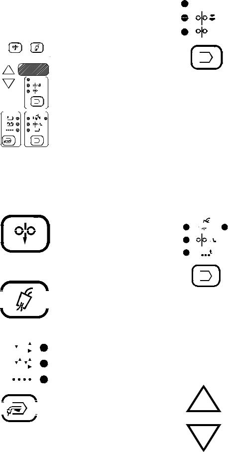
K E Y P A D A N D D I S P L A Y DESCRIPTION
Keypad - Seven key, membrane
type with “snap” tactile feel and
COLD FEED GAS PURGE
 embossed domes. Long life
 design. Spatter resistant surface.
V VOLTS / TRIM


 RUN-IN
WFS
TRIGGER MODE
|
PREFLOW |
POSTFLOW |
2-STEP |
1 |
2 |
STD |
|
|
4-STEP |
|
CRATER |
LOCK |
|
|
|
|
|
SPOT |
|
SPOT |
|
|
Display - 3-1/2 digit 7-segment LED with (+) or (-) polarity indicators. .56” (14.2mm) character height. Displays arc voltage in volts, wire speed in IPM or m/m and all timers in seconds.
Indicator Lights - Extra bright red LED’s for viewing at almost any angle. Always indicates the mode being used and which function or timer is beiing displlayed.. A function and a timer light will never be on at the same time since they can only be displayed one at a time.
Cold Feed key energizes the wire feeder but not the power source or solenoid valve. Cold feed speed is adjustable and is displayed only while pressing Cold Inch, and the last speed selected is stored in
|
|
|
|
|
|
|
|
|
|
|
|
|
|
|
|
|
|
memory for next Cold feeding. |
|
|
|
|
|
|
|
|
|
|
|
|
|
|
|
|
|
|
Gas Purge key energizes the |
|
|
|
|
|
|
|
|
|
|
|
|
|
|
|
|
|
|
|
|
|
|
|
|
|
|
|
|
|
|
|
|
|
|
|
|
|
solenoid valve but not the wire |
|
|
|
|
|
|
|
|
|
|
|
|
|
|
|
|
|
|
feeder or power source. |
|
|
|
|
|
|
|
|
|
|
|
|
|
|
|
|
|
|
Mode Select key enables operator |
|
|
|
|
|
|
|
|
|
|
|
|
|
|
|
|
|
|
to choose mode of operation shown |
|
|
|
|
|
|
|
|
|
|
|
by the indicator lights. Pressing key |
|||||||
|
2-STEP |
|
|
|
|
|
||||||||||||
|
|
|
|
|
|
|||||||||||||
|
STD |
|
|
|
|
|
|
|
|
|
|
causes mode lights to sequence |
||||||
|
|
|
|
|
|
|
||||||||||||
|
|
|
|
|
|
|
|
|
|
|
|
|
|
|
|
|
|
|
|
|
|
|
|
|
|
|
|
|
|
|
|
(top to bottom) starting from the |
|||||
|
4-STEP |
|
|
|
|
|
|
|
||||||||||
|
|
|
|
|
|
|
|
|||||||||||
|
LOCK |
|
|
|
|
|
|
|
|
|
|
current indicated selection. |
||||||
|
|
|
|
|
|
|
|
|
|
|||||||||
|
|
|
|
|
|
|
|
|
|
|
|
|
|
|
|
|
|
|
|
SPOT |
|
|
|
|
Top Light - Indicates 2-step |
||||||||||||
|
|
|
|
|
|
|
|
|
|
|
|
|
|
|
|
|
|
|
|
|
|
|
|
|
|
|
|
|
|
|
|
|
|
|
|
|
(standard) trigger mode. |
|
|
|
|
|
|
|
|
|
|
|
|
|
|
|
|
|
|
Middle Light - Indicates 4-step |
|
|
|
|
|
|
|
|
|
|
|
|
|
|
|
|
|
|
|
|
|
|
|
|
|
|
|
|
|
|
|
|
|
|
|
|||
|
|
|
|
|
|
|
|
|
|
|
|
|
|
|
|
|||
|
|
|
|
|
|
|
|
|
|
|
|
|
|
|
|
|||
|
|
|
|
|
|
|
|
|
|
|
|
|
|
|
|
|
|
(lock) trigger mode. This mode may |
|
|
|
|
|
|
|
|
|
|
|
|
|
|
|
|
|||
|
|
|
|
|
|
|
|
|
|
|
|
|
|
|
|
|||
|
|
|
|
|
|
|
|
|
|
|
|
|
|
|
|
|
|
be selected to include crater fill or |
|
|
|
|
|
|
|
|
|
|
|
|
|
|
|
|
|||
|
|
|
|
|
|
|
|
|
|
|
|
|
|
|
|
|
|
weld current interlock. |
|
|
|
|
|
|
|
|
|
|
|
|
|
|
|
|
|
|
Bottom Light - Indicates spot weld |
|
|
|
|
|
|
|
|
|
|
|
|
|
|
|
|
|
|
mode. |
V |
VOLTS |
/ TRIM |
|
RUN-IN
WFS
PREFLOW |
POSTFLOW |

 1
1


 2
2
CRATER
SPOT
Function Select key enables operator to choose which function will be displayed as shown by the appropriate indicator light. Pressing the key causes lights to sequence (top to bottom) starting from the current indicated position. The function displayed will be adjustable with the rotating encoders or arrow keys.
Top Light - Indicates display of preset voltage or percent trim when not welding and arc voltage while welding (as indicated by top light “blinking”). The power source automatically determines whether preset voltage or percent trim will be displayed, and adjustable with Volts/Trim rotating encoder control.
Middle Light - Indicates Run-in speed is being displayed. As shipped, these models are setup for a 50 IPM (1.27m/min) fixed run-in speed with display function deactivated. They may be user-selected to activate or deactivate adjustable Run-in display.
Bottom Light - Indicates Weld Feed Speed (WFS) is being displayed, and is adjustable with the Wire Feed Speed rotating encoder control.
Timer/Crater Select key enables operator to choose spot or gas timers, or crater speed as indicated by the appropriate light. Pressing the key causes lights to sequence (left to right, top to bottom) starting from the current indicated selection. Any parameter not available in the mode selected is skipped over.
Top Left Light - indicates preflow time is being displayed in seconds.
Top Right Light - indicates postflow time is being displayed in seconds.
Middle Light - indicates Crater Feed Speed is being displayed. This display will only occur if 4-step mode with crater fill is selected.
Bottom Light - indicates spot on time is being displayed in seconds.
Increase arrow key increases the setting of the parameter selected to be displayed. Arrow keys do not function for Wire Feed Speed or Volts/Trim settings, which are adjusted using the rotating encoder knobs.
Decrease arrow key decreases the setting of the parameter selected to be displayed. Arrow keys do not function for Wire Feed Speed or Volts/Trim settings, which are adjusted using the rotating encoder knobs.
– 9 –
OPTIONAL FEATURES
DRIVE ROLL AND GUIDE TUBE KITS:
Steel Wire Sizes: |
4-Roll |
|
* |
.068 - 3/32” (1.7 - 2.4mm) Cored |
KP655-3/32 |
* |
1/16” (1.6mm) Cored or Solid |
KP655-1/16 |
|
.045 - .052” (1.2 - 1.4mm) Solid |
KP655-052S |
|
.045 - .052” (1.2 - 1.4mm) Cored |
KP655-052C |
|
.035” (0.9-1.0mm) Cored |
KP655-035C |
|
.035” (0.9-1.0mm) Solid |
KP655-035S |
|
.030” (0.8mm) Solid |
KP655-030S |
|
.023” (0.6mm) Solid |
KP655-025S |
Aluminum Wire Sizes: |
|
|
|
1/16” (1.6mm) |
KP656-1/16A |
|
|
KP647-1/16A** |
|
3/64” (1.2mm) |
KP656-3/64A |
|
|
KP647-3/64A** |
|
.040” (1.0mm) |
KP647-040A** |
|
.035” (0.9mm) |
KP656-035A |
Drive rolls for only cored electrode sizes are stencilled with a “C” suffix to the wire sizes.
Drive rolls for only solid electrode sizes are stencilled with an “S” suffix to the wire sizes.
Drive rolls for aluminum wire sizes are stencilled with an “A” suffix to the wire sizes.
* Not for Synergic 7H model.
**For use with Binzel European guns. Installation instructions are included with these kits.
INPUT CABLE ASSEMBLIES:
K649 - (Used with Power Wave 450/500) Consists of an 8- conductor control cable with 14-pin control cable plug and a 4/0 (107 mm2) electrode cable with Twist-Mate™ connector. It is rated at 500 amps, 60% duty cycle and is available in lengths of 7 ft. (2 m), 17 ft (5 m), 25 ft (7.6 m), 33 ft (10 m), and 50 ft (15 m).
K648 - (Used with Power Wave 450) Consists of an 8- conductor control cable with a 14-pin plug and a 4/0 (107 mm2) electrode cable with stud terminal. It is rated at 500 amps, 60% duty cycle and is available in lengths of 7 ft (2 m), 17 ft (5 m), 25 ft (7.6 m), 33 ft (10 m) and 50 ft (15 m).
K651 - (Used with Power Wave 350) Consists of an 8- conductor control cable with 14-pin control cable plug and a 2/0 (67 mm2) electrode cable with Twist-Mate™ connector. It is rated at 350 amps, 60% duty cycle and is available in lengths of 7 ft. (2 m), 17 ft (5 m), 33 ft (10 m), and 50 ft (15 m).
K642 - (Control Cable only) Consists of an 8-conductor control cable with 14-pin control cable plug, without electrode cable, and is available in lengths of 7 ft (2 m), 17 ft (5 m), 25 ft (7.6 m), 33 ft (10 m) and 50 ft (15 m).
K643 (Control Cable Extension) Consists of an 8-conductor control cable with 14-pin connectors on each end for extending the control cable between the power source and the control cable. Available in lengths of 17 ft (5m), 25 ft (7.6m), 33 ft (10m), and 50 ft (15m).
WIRE REEL ASSEMBLY:
K299 - Wire reel assembly for customer mounting. Includes 50 - 60 lb wire reel spindle shaft, adjustable brake, insulation and mounting hardware.
READI-REEL ADAPTERS:
K363P - Adapts Lincoln Readi-Reel coils of electrode 30 lb (14 kg) and 22 lb (10 kg) to a 2” (51mm) spindle. Durable molded plastic one piece construction. Designed for easy loading; adapter remains on spindle for quick changeover. (used with K162H)
K438 - Adapts Lincoln Readi-Reel coils of electrode 50-60 lb (22.7-27.2 kg) to a 2” (51mm) spindle. (used with K162H).
SPINDLE ADAPTERS:
K162H - Spindle for mounting Readi-Reels and 2” (51mm) I.D. spools with 60 lb (27.2 kg) capacity. The shaft for the standard wire coils is removed from the mounting framework and the K162H is installed in its place. Includes an easily adjustable friction brake for control of overrun.
When used with Readi-Reels a Readi-Reel adapter is required.
K435 - Permits 14 lb (6 kg) Innershield coils to be mounted on 2” (51mm) O.D. spindles. For use with optional K162H adapter.
K468 - Permits 8” (203mm) O.D. spools to be mounted on 2” (51mm) O.D. spindles. For use with optional K162H adapter.
GUN AND CABLE ASSEMBLIES:
The following Lincoln gun and cable assemblies are compatible with both the Synergic 7F and Synergic 7FH Wire Feed units:
K126 - Innershield® gun and cable assemblies are rated at 350 amps, 60% duty cycle. Maximum wire size for Synergic 7F models is 5/64” (2.0 mm). Not recommended for Synergic 7FH models. (Consult sales specifications for appropriate models).
K115 - Innershield gun and cable assemblies are rated at 450 amps, 60% duty cycle. Maximum wire size for Synergic 7F models is 5/64” (2.0 mm). Not recommended for Synergic 7FH models. (Consult sales specifications for appropriate models).
K470 - Magnum 300 GMAW gun and cable assemblies are rated for 300 amps, 60% duty cycle. (Consult sales specifications for appropriate models).
K471 - Magnum 400 GMAW gun and cable assemblies are rated for 400 amps, 60% duty cycle. (Consult sales specifications for appropriate models).
K497 - Magnum 200 GMAW gun and cable assemblies are rated 200 amps, 60% duty cycle. (Consult sales specifications for appropriate models).
– 10 –
K541 - Magnum 400 Short Neck GMAW gun and cable assemblies are rated 400 amps, 60% duty cycle. (Consult sales specifications for appropriate models).
K598 - Magnum 550 GMAW gun and cable assemblies are rated 550 amps, 60% duty cycle. (Consult sales specifications for appropriate models).
K206* - Innershield Linconditioner gun and cable assemblies are rated 350 amps, 60% duty cycle. Maximum size for Synergic 7F Wire Feed unit is 5/64” (2.0 mm). Not recommended for Synergic 7FH Wire Feed unit. (Consult sales specifications for appropriate models).
K289* - Innershield Linconditioner gun and cable assemblies are rated 500 amps, 60% duty cycle. Maximum size for Synergic 7F Wire Feed unit is 5/64” (2.0 mm). Not recommended for Synergic 7FH Wire Feed unit. (Consult sales specifications for appropriate models).
K309* - Innershield Linconditioner gun and cable assemblies are rated 250 amps, 60% duty cycle. Maximum size for Synergic 7F Wire Feed unit is 5/64” (2.0 mm). Not recommended for Synergic 7FH Wire Feed unit. (Consult sales specifications for appropriate models).
The following Lincoln gun and cable assemblies are equipped with a Fast-Mate™ connector. They can be used with Synergic 7F Wire Feed unit by installing a K489-2 Fast-Mate adapter kit.
K684 - Magnum “Super Cool” FM water cooled GMAW gun and cable assemblies are rated 450 amps, 100% duty cycle (CO2). (Consult sales specifications for appropriate models).
K498 - Magnum 200 FM GMAW gun and cable assemblies are rated for 200 amps, 60% duty cycle. (Consult sales specifications for appropriate models).
K534 - Magnum 250L FM GMAW gun and cable assemblies are rated for 250 amps, 30% duty cycle. (Consult sales specifications for appropriate models).
K478 - Magnum 300 FM GMAW gun and cable assemblies are rated for 300 amps, 60% duty cycle. (Consult sales specifications for appropriate models).
K479 - Magnum 400 FM GMAW gun and cable assemblies are rated for 400 amps, 60% duty cycle. (Consult sales specifications for appropriate models).
K556 * - GMAW process Magnum 400XA X- TRACTOR gun and cable assemblies are rated at 400 amps, 60% duty cycle. (Consult sales specifications for appropriate models).
K566 * - GMAW process Magnum 250XA X- TRACTOR gun and cable assemblies are rated 250 amps, 60% duty cycle. (Consult sales specifications for appropriate models).
*K179 type vacuum unit not recommended for use with Synergic 7F.
MISCELLANEOUS OPTIONS:
K682 Water Connection Kit - Includes water cooled gun tube fittings and self-sealing outlet and inlet quickconnectors for mounting onto the Synergic 7F Wire Drive mounting bracket.
K659-1 - (Gas Guard Regulator) Adjustable flow regulator with removable adjustor key for CO2 and Argon blend gases.
Mounts onto Wire Drive gas inlet, and reduces gas waste and arc start “blow” by reducing surge caused by excess pressure in supply hose.
K683-1 - (Dual Procedure Switch) Kit includes gun switch and mountings for Lincoln Innershield and Magnum guns with 15 ft (4.6 m) control cable and 3-pin plug.
– 11 –
SPECIFICATIONS FOR SYNERGIC 7F
AND SYNERGIC 7FH
|
CONTROL |
WIRE FEED - (4 - ROLL) |
|
|
||
|
|
|
|
|
||
Model |
SYNERGIC 7F |
SYNERGIC 7F |
SYNERGIC 7FH |
|
||
|
|
|
|
|
||
Type |
K678-1 |
K679-1 |
K679-2 |
|
||
|
|
|
|
|
|
|
Wire Speed Range: |
|
|
|
|
|
|
IPM |
|
50 - 770 |
80 - 1200 |
|
||
M/M |
|
1.25 - 19.5 |
2.00 |
- |
30.5 |
|
|
|
|
|
|
|
|
Wire Size Capabilities: |
|
|
|
|
|
|
Solid Electrodes |
.025 - 1/16” |
.025 - 1/16” |
.025 |
- |
.045” |
|
|
0.6 - 1.6mm |
0.6 - 1.6mm |
0.6 - 1.2mm |
|
||
Cored Electrodes |
.045 - 3/32” |
.045 - 3/32” |
.045” |
|
||
|
1.2 - 2.4mm |
1.2 - 2.4mm |
1.2mm |
|
||
|
|
|
|
|
|
|
Input Power: |
40-42 V ± 10% |
|
|
|
|
|
|
50/60 Hz |
|
|
|
|
|
|
4.0 Amps |
|
|
|
|
|
|
|
|
|
|
|
|
Temperature Rating: |
|
|
|
|
|
|
Operating |
|
-20°C to +40°C |
|
|
|
|
Storage |
|
-40°C to +40°C |
|
|
|
|
|
|
|
|
|
|
|
Dimensions: |
|
|
|
|
|
|
Height |
13.31” (338.1 mm) |
11.25” (285.8 mm) |
|
|
|
|
Width |
10.32” (262.1 mm) |
7.16” (181.9 mm) |
|
|
|
|
Depth |
6.16” (156.5 mm) |
8.06” (204.7 mm) |
|
|
|
|
|
|
|
|
|
|
|
Weight |
13.25 lbs (6.0 Kg) |
16.5 lbs (7.5 Kg) |
|
|
|
|
|
|
|
|
|
|
|
– 12 –

INSTALLATION
Safety Precautions
 WARNING
ELECTRIC SHOCK can kill.
•Do not touch electrically live parts such as output terminals or internal wiring.
•When inching with gun trigger, electrode and drive mechanism are “hot” to work and ground.
•Turn OFF welding power source before installing or changing drive roll and/or guide tubes.
•Welding power source must be connected to system ground per the National Electrical Code or any applicable local codes.
•Only qualified personnel should perform this installation.
Observe all additional Safety Guidelines detailed throughout this manual.
INSTALLATION OF THE SYNERGIC 7F COMPONENTS
Mounting the Wire Feed Unit (K679-1 or -2)
Mount the wire feed unit by means of the insulated mounting bracket attached to the bottom of the gearbox. Reference L9777 dimension print at the rear of this manual to find the size and location of the mounting holes. The gearbox assembly is electrically “hot” when the gun trigger is pressed. Therefore, make certain the gearbox does not come in contact with the structure on which the unit is mounted.
The wire feed unit should be mounted so that the drive rolls are in a vertical plane so dirt will not collect in the drive roll area. Position the mechanism so it will point down at about a 45° angle so the wire feed gun cable will not be bent sharply as it comes from the unit.
Mounting the Control Box (K678-1)
The same control box is used for both the Synergic 7F and Synergic 7FH wire feed units and contains two keyhole slots and one slot for mounting. Reference M17740 dimension print in the rear of this manual for size and location of these slots. Mount the box at some convenient location close to the wire feed unit which will enable the desired control cable assembly to reach between the control box and the wire feed unit.
a)Drill the required holes in the mounting surface, partially install 1/4-20 screws.
b)Open the control box door by removing the two door screws.
c)Mount the box.
d)Tighten the screws.
e)Close the control box door and replace the door screws.
Connecting Wire Feed Unit to Control Box
The Feeder to Control cable assemblies are available in two types:
K680-”L” Includes a control cable with 14-pin MSstyle connectors on each end, and a 4/0 weld cable to route between the Wire Drive and the Control Box. Available in lengths “L” of 16ft. (4.9m) and 25ft. (7.6m).
K681-”L” Same as K680, but does not include weld cable. Available in lengths “L” of 12ft. (3.6m), 16ft. (4.9m) and 25ft. (7.6m).
1.Making certain the cables are protected from any sharp corners which may damage their jackets, mount the cable assembly along the boom so the end with the female MS-style connector pins is at the wire feed unit.
2.Connect the 14-socket cable connector to the receptacle on the back of the wire feed unit connection box.
3.At the same end, connect the electrode lead to the connection stud of the brass gun connection block on the front of the wire feed unit.
4.At the control box end, connect the 14-pin connector of the cable to the mating receptacle on the bottom of the control box.
Electrode Routing
The electrode supply may be either from reels, ReadiReels, spools or bulk packaged drums or reels. Observe the following precautions:
1.The electrode must be routed to the wire feed unit so that the bends in the wire are at a minimum, and also that the force required to pull the wire from the reel into the wire feed unit is kept at a minimum.
2.The electrode is “hot” when the gun is energized and must be insulated from the boom and structure.
3.If more than one wire feed unit shares the same boom, their wire and reels must be insulated from each other and insulated from their mounting structure.
– 13 –
Wire Feed Drive Roll and Guide Tube Kits
NOTE: The maximum sizes the Synergic 7F will feed satisfactorily are the 3/32” (2.4mm) cored and 1/16” (1.6mm) solid electrodes. The maximum sizes the synergic 7FH will feed satisfactorily are the .045 (1.2mm) cored and
.045” (1.2mm) solid electrodes.
The electrode sizes that can be fed with each roll and guide tube are stencilled on each part. Check the kit for proper components.
Steel Wire Sizes: |
4-Roll |
|
* |
.068 - 3/32” (1.7 - 2.4mm) Cored |
KP655-3/32 |
* |
1/16” (1.6mm) Cored or Solid |
KP655-1/16 |
|
.045 - .052” (1.2 - 1.4mm) Solid |
KP655-052S |
|
.045 - .052” (1.2 - 1.4mm) Cored |
KP655-052C |
|
.035” (0.9-1.0mm) Cored |
KP655-035C |
|
.035” (0.9-1.0mm) Solid |
KP655-035S |
|
.030” (0.8mm) Solid |
KP655-030S |
|
.023” (0.6mm) Solid |
KP655-025S |
Aluminum Wire Sizes: |
|
|
|
1/16” (1.6mm) |
KP656-1/16A |
|
|
KP647-1/16A** |
|
3/64” (1.2mm) |
KP656-3/64A |
|
|
KP647-3/64A** |
|
.040” (1.0mm) |
KP647-040A** |
|
.035” (0.9mm) |
KP656-035A |
Drive rolls for only cored electrode sizes are stencilled with a “C” suffix to the wire sizes.
Drive rolls for only solid electrode sizes are stencilled with an “S” suffix to the wire sizes.
Drive rolls for aluminum wire sizes are stencilled with an “A” suffix to the wire sizes.
* Not for Synergic 7H model.
**For use with Binzel European guns. Installation instructions are included with these kits.
PROCEDURE TO INSTALL DRIVE ROLL AND GUIDE TUBES
 WARNING
ELECTRIC SHOCK can kill.
•Do not touch electrically live parts such as output terminals or internal wiring.
•When inching with gun trigger, electrode and drive mechanism are “hot” to work and ground.
•Turn OFF welding power source before installing or changing drive roll and/or guide tubes.
•Welding power source must be connected to system ground per the National Electrical Code or any applicable local codes.
•Only qualified personnel should perform this installation.
Observe all additional Safety Guidelines detailed throughout this manual.
Standard 4-Roll Kits (KP571 and KP572)
1)Turn off welding power source.
2)Release both quick release levers by sliding the levers sideways into the open positions.
3)Remove hex screw & clamping collar from the drive shaft closest to the incoming side of the feeder.
4)Install drive roll onto keyed shaft. Double grooved drive rolls are to be installed with side stencilled for correct wire size facing out and with slotted spacer on top of roll. Two piece drive rolls use a spacer between the rolls for .068” (1.7mm) and larger wire sizes. (Do not exceed the maximum wire size rating of the wire drive.) Replace collar and tighten clamping screw.
5)Back out the set screw for the middle guide tube. Install the middle guide tube and slide it up against the drive roll. DO NOT TIGHTEN THE MIDDLE GUIDE AT THIS TIME.
6)Install the outgoing drive roll following the same procedure as steps 3 & 4.
7)Center the middle guide between the two drive rolls and tighten in place.
– 14 –
 Loading...