


 Loading...
Return to Master TOC |
View Safety Info |
Return to Master TOC |
View Safety Info |
Return to Master TOC |
View Safety Info |
RETURN TO MAIN INDEX
LN-7 GMA Wire Feeder
For use with machines having Code Numbers: 9168
9386
9643
9796
9928
9931
Safety Depends on You
Lincoln arc welding equipment is designed and built with safety in mind. However, your overall safety can be increased by proper installation ... and thoughtful operation on your part. DO NOT INSTALL,
OPERATE OR REPAIR THIS EQUIPMENT WITHOUT READING THIS MANUAL AND THE SAFETY PRECAUTIONS CONTAINED THROUGHOUT. And, most importantly, think before you act and be careful.
LN- |
|
|
|
|
7 |
GMA |
|
||
|
CONTROLMINUTE |
|||
|
|
WIRE |
||
|
INCHES |
PERSPEED |
||
250 |
300 |
350 |
||
|
|
400 |
|
|
200 |
|
|
|
450 |
150 |
|
|
|
500 |
100 |
|
|
|
550 |
|
|
|
|
600 |
|
|
|
|
650 |
|
|
|
|
700 |
This |
|
SERIAL |
NO. |
|
|
|
|
|
|
|
|
|
|
|
|
|
|
||||
followingmachine |
|
|
|
|
|
|
|
|
|
|
|
|
|
|
|
|
|||||
4,247,751;patents: |
the |
|
|
|
|
|
|
|
|
|
|
|
|
|
|
|
|
||||
7,803,421; |
|
and |
|
|
|
|
|
|
|
|
|
|
|
|
|
|
|
|
|
||
European |
AustraliaPI United |
|
|
|
|
|
|
|
|
|
|
|
|
|
|
|
|||||
Netherlands,Patent |
|
accessoriesstates |
are |
|
|
|
|
|
|
|
|
|
|
||||||||
1,102,502; |
|
7,905,509;467,447; |
|
|
|
CODE |
|
|
|
|
|||||||||||
OtherKingdom |
|
|
Italy,8527 |
(France,499,502;3,806,695; 3. |
NO. |
|
|
||||||||||||||
|
patents |
|
|
by |
|
|
|
|
|
||||||||||||
|
|
|
Mexico |
|
|
Canada |
|
|
covered |
|
one |
|
|
|
|
|
|
||||
|
|
1,529,726;Sweden); |
|
West965,487; |
|
|
or |
|
|
|
|
||||||||||
|
|
|
|
|
147,019; |
|
|
|
|
|
|
|
|
||||||||
|
|
|
|
pending. |
|
SFrance. |
|
517,120;975,616; |
|
|
|
|
|
|
|||||||
|
|
|
|
|
1,579,700;Korea |
Germany, |
|
|
|
|
of |
|
|
||||||||
|
|
|
|
|
|
|
|
|
W. |
|
|
01477;1,041,181;525,541;4,246,463;the |
|
||||||||
|
|
|
|
|
|
|
|
|
|
|
73. |
|
|
|
|
|
more |
|
|
|
|
|
|
|
|
|
|
|
|
|
|
|
|
19064; |
|
75United |
|
Brazil |
|
|
|
||
|
|
|
|
|
|
|
|
|
|
Germany |
|
|
|
1,093,159; |
|
|
|||||
|
|
|
|
|
|
|
|
|
|
|
|
|
25Sweden34477; |
|
79,787; |
PI |
|||||
|
|
|
|
|
|
|
|
|
|
|
|
|
|
50 |
|
|
Kingdom, |
|
|||
|
|
|
|
|
|
|
|
|
|
|
|
|
|
|
|
780511228 14757l- 1,119,674; |
|||||
|
|
|
|
|
|
|
|
|
|
|
|
|
|
|
278; |
23 |
5; |
Italy |
|
||
|
|
|
|
|
|
|
|
|
|
|
|
|
|
|
|
|
|
|
293United. |
||
LN- |
|||
|
|
|
7 |
115V, |
NEMA |
EW3 |
|
|
50/60 |
|
|
|
|
HZ |
|
|
|
|
AMPS |
LN-7 GMA shown with optional K417 digital meter kit and K418 GMA timer kit.
SVM 106-A
February, 1995
ELECTRODE POLARITY POSITIVE
NEGATIVE
. CO  ELECTRIC
VOLTS
U.S.A. OH CLEVELAND,
LINCOLN |
|
|
|
|
|
|
|
|
|
|
|
|
|
|
|
|
|
& OTHERS |
|
|
|
|
|
|
|
|
|
|
|
|
|
|
|
|
|
|
|
|
. |
THE |
|
|
|
|
|
|
|
|
|
|
|
|
|
|
YOURSELFbe |
|
|||
|
|
|
|
|
|
|
|
|
|
|
|
|
|
|
can |
|
|
||
|
|
|
|
|
|
|
|
|
|
|
|
|
|
PROTECTGASEShealth |
|
|
|||
|
|
|
|
|
|
|
|
|
|
|
|
|
|
|
your |
|
|
|
|
|
|
|
|
|
|
|
|
|
|
|
|
|
WARNING,ANDto |
|
|
|
|
||
|
|
|
|
|
|
|
|
|
|
|
|
THIS FUMES |
|
|
cause |
|
|||
|
|
|
|
|
|
|
|
|
|
|
READ |
dangerous |
can |
|
|
|
|||
|
|
|
|
|
|
|
|
|
|
|
|
|
|
SPARKS. |
|
|
|
|
|
|
|
|
|
|
|
|
|
|
|
|
|
|
|
explosion |
eyes and |
|
|||
|
|
|
|
|
|
|
|
|
|
|
|
|
WELDINGor |
injure |
|
|
|
DEDE |
|
|
WARNING |
|
|
fire |
|
|
|
RISQUESZONE. |
|||||||||||
|
|
PUR |
by |
Available |
|
UTILISATION |
|||||||||||||
|
|
|
|
|
|
|
|
|
|
|
|
|
|
RAYS. |
can |
|
|||
|
|
|
|
|
|
|
|
|
|
|
|
|
|
|
|
DES |
LA |
|
|
|
|
|
|
|
|
|
|
|
|
|
|
|
|
|
|
|
DANIS |
Society, |
|
|
|
|
|
|
|
|
|
|
|
|
|
|
ARC |
skin |
COMPORTEAVANT |
|
|||
|
|
|
|
|
|
|
|
|
kill |
|
|
|
|
PERSONNES |
Welding. GovernmentM16196 |
||||
|
|
|
|
|
|
|
|
can |
|
|
|
|
|
OULESTECHNIQUE |
|
U.S VM |
|
||
|
|
|
|
|
|
SHOCK |
|
|
|
|
|
LA SOUDURENOTICE |
Americanfrom |
|
|
|
|||
|
|
|
|
|
|
|
|
|
|
|
L'OPERATEURLA |
the |
|
|
|
|
|||
|
|
ELECTRIC |
|
|
|
|
|
AVERTISEMENT:. CONSULTER |
1910 |
|
|
|
|
|
|||||
|
|
|
|
|
|
|
|
|
|
|
BLESSRES |
published |
|
|
|
|
|
||
|
|
|
|
|
|
|
|
|
|
|
TRAVAIL |
CFR |
|
|
|
|
|
||
|
|
|
|
|
|
|
|
|
|
THIS |
Cutting", |
29 |
|
|
|
|
|
|
|
|
|
|
|
|
|
|
|
|
SERVICEINSTRUCTIONS, |
andStandards,WARNING |
|
|
|
|
|
|
|||
|
|
|
|
|
|
|
|
|
|
SHEETS |
|
|
|
|
|
|
|
|
|
|
|
|
|
|
|
|
|
|
OF |
DATA |
|
|
|
|
|
|
|
|
|
|
|
|
|
|
|
|
|
|
SAFETY |
in Welding |
|
|
|
|
|
|
|
||
|
|
|
|
|
|
|
|
USE |
|
|
HeathTHIS |
|
|
|
|
|
|
|
|
|
|
|
|
|
|
MANUFACTURE'S |
REMOVE |
|
|
|
|
|
|
|
|||||
|
|
|
|
|
|
INSTALL, |
|
and |
|
|
|
|
|
|
|
|
|
||
|
|
|
|
|
SHOULDTHE |
MATERIAL |
"SafetySafety |
|
|
|
|
|
|
|
|
|
|||
|
|
|
|
|
|
AND |
|
.1 |
|
NOT |
|
|
|
|
|
|
|
|
|
|
|
|
|
FOLLOW |
|
Z |
49 |
OSHA |
|
|
|
|
|
|
|
|
|
|
|
|
|
|
|
|
|
. DO |
|
|
|
|
|
|
|
|
|
|
|||
|
|
PERSONALANDPRACTICES. |
|
33126; |
|
|
|
|
|
|
|
|
|
|
|
||||
ONLY |
|
READ |
|
|
Standard. 20402 |
|
|
|
|
|
|
|
|
|
|
|
|||
CONSUMABLES |
FloridaD.C |
|
|
|
|
|
|
|
|
|
|
|
|
||||||
QUALIFIED. SAFETY |
|
|
|
|
|
|
|
|
|
|
|
|
|
||||||
EQUIPMENTFOR |
|
NationalMiami,. |
|
|
|
|
|
|
|
|
|
|
|
|
|
|
|||
EMPLOYER'S |
Rd |
|
|
|
|
|
|
|
|
|
|
|
|
|
|
|
|
||
(MSDS)American |
Washington, |
|
|
|
|
|
|
|
|
|
|
|
|
|
|||||
SeeLe |
Jeune |
|
|
|
|
|
|
|
|
|
|
|
|
|
|
|
|
|
|
Office, |
|
|
|
|
|
|
|
|
|
|
|
|
|
|
|
|
|
||
550 |
|
|
|
|
|
|
|
|
|
|
|
|
|
|
|
|
|
|
|
Printing |
|
|
|
|
|
|
|
|
|
|
|
|
|
|
|
|
|
|
|
Return to Master TOC |
aView Safety Info |
SERVICE MANUAL
|
|
|
|
|
|
|
|
|
|
|
|
World’s Leader in Welding and Cutting Products |
|
|
|
Premier Manufacturer of Industrial Motors |
|
|
|
|
|||
Sales and Service through Subsidiaries and Distributors Worldwide
22801 St. Clair Ave. Cleveland, Ohio 44117-1199 U.S.A. Tel (216) 481-8100
Return to Master TOC
Return to Master TOC
Return to Master TOC
Return to Master TOC
i |
SAFETY |
WARNING |
ARC WELDING can be hazardous. |
PROTECT YOURSELF AND OTHERS FROM POSSIBLE SERIOUS INJURY OR DEATH. KEEP CHILDREN AWAY. PACEMAKER WEARERS SHOULD CONSULT WITH THEIR DOCTOR BEFORE OPERATING.
Read and understand the following safety highlights. For additional safety information, it is strongly recommended that you purchase a copy of “Safety in Welding & Cutting - ANSI Standard Z49.1” from the American Welding Society, P.O. Box 351040, Miami, Florida 33135 or CSA Standard W117.2-1974. A Free copy of “Arc Welding Safety” booklet E205 is available from the Lincoln Electric Company, 22801 St. Clair Avenue, Cleveland, Ohio 44117-1199.
BE SURE THAT ALL INSTALLATION, OPERATION, MAINTENANCE AND REPAIR PROCEDURES ARE PERFORMED ONLY BY QUALIFIED INDIVIDUALS.
ELECTRIC SHOCK
can kill.
1.a. The electrode and work (or ground) circuits are electrically “hot” when the welder is on. Do not touch these “hot” parts with your bare skin or wet clothing. Wear dry, hole-free gloves to insulate hands.
1.b. Insulate yourself from work and ground using dry insulation. Make certain the insulation is large enough to cover your full area of physical contact with work and ground.
In addition to the normal safety precautions, if welding must be performed under electrically hazardous conditions (in damp locations or while wearing wet clothing; on metal structures such as floors, gratings or scaffolds; when in cramped positions such as sitting, kneeling or lying, if there is a high risk of unavoidable or accidental contact with the workpieceor ground) use the following equipment:
•Semiautomatic DC Constant Voltage (Wire) Welder.
•DC Manual (Stick) Welder.
•AC Welder with Reduced Voltage Control.
1.c. In semiautomatic or automatic wire welding, the electrode, electrode reel, welding head, nozzle or semiautomatic welding gun are also electrically “hot”.
1.d. Always be sure the work cable makes a good electrical connection with the metal being welded. The connection should be as close as possible to the area being welded.
1.e. Ground the work or metal to be welded to a good electrical (earth) ground.
1.f. Maintain the electrode holder, work clamp, welding cable and welding machine in good, safe operating condition. Replace damaged insulation.
1.g. Never dip the electrode in water for cooling.
1.h. Never simultaneously touch electrically “hot” parts of electrode holders connected to two welders because voltage between the two can be the total of the open circuit voltage of both welders.
1.i. When working above floor level, use a safety belt to protect yourself from a fall should you get a shock.
1.j. Also see Items 4.c. and 6.
ARC RAYS can burn.
2.a. Use a shield with the proper filter and cover plates to protect your eyes from sparks and the rays of the arc when welding or observing open arc welding. Headshield and filter lens should conform to ANSI Z87. I standards.
2.b. Use suitable clothing made from durable flame-resistant material to protect your skin and that of your helpers from the arc rays.
2.c. Protect other nearby personnel with suitable, non-flammable screening and/or warn them not to watch the arc nor expose themselves to the arc rays or to hot spatter or metal.
FUMES AND GASES can be dangerous.
3.a. Welding may produce fumes and gases
hazardous to health. Avoid breathing these fumes and gases. When welding, keep your head out of the fume. Use enough ventilation and/or exhaust at the arc to keep fumes and gases away from the breathing zone. When welding with
electrodes which require special ventilation such as stainless or hard facing (see instructions on container or MSDS) or on lead or cadmium plated steel and other metals or coatings which produce highly toxic fumes, keep exposure as low as possible and below Threshold Limit Values (TLV) using local exhaust or mechanical ventilation. In confined spaces or in some circumstances, outdoors, a respirator may be required. Additional precautions are also required when welding on galvanized steel.
3.b. Do not weld in locations near chlorinated hydrocarbon vapors coming from degreasing, cleaning or spraying operations. The heat and rays of the arc can react with solvent vapors to form phosgene, a highly toxic gas, and other irritating products.
3.c. Shielding gases used for arc welding can displace air and cause injury or death. Always use enough ventilation, especially in confined areas, to insure breathing air is safe.
3.d. Read and understand the manufacturer’s instructions for this equipment and the consumables to be used, including the material safety data sheet (MSDS) and follow your employer’s safety practices. MSDS forms are available from your welding distributor or from the manufacturer.
3.e. Also see item 7b.
LN-7 GMA WIRE FEEDER
Return to Master TOC
Return to Master TOC
Return to Master TOC
Return to Master TOC
SAFETY |
ii |
WELDING SPARKS can

 cause fire or explosion.
4.a. Remove fire hazards from the welding area. If this is not possible, cover them to prevent the welding sparks from starting a fire.
Remember that welding sparks and hot materials from welding or cutting can easily go through small cracks and openings to adjacent areas. Avoid welding or cutting near hydraulic lines. Have a fire extinguisher readily available.
4.b. Where compressed gases are to be used at the job site, special precautions should be used to prevent hazardous situations. Refer to “Safety in Welding and Cutting” (ANSI Standard Z49.1) and the operating information for the equipment being used.
4.c. When not welding, make certain no part of the electrode circuit is touching the work or ground. Accidental contact can cause overheating and create a fire hazard.
4.d. Do not heat, cut or weld tanks, drums or containers until the proper steps have been taken to insure that such procedures will not cause flammable or toxic vapors from substances inside. They can cause an explosion even though they have been “cleaned”. For information, purchase “Recommended Safe Practices for the Preparation for Welding and Cutting of
Containers and Piping That Have Held Hazardous Substances”, AWS F4.1 from the American Welding Society
(see address above).
4.e. Vent hollow castings or containers before heating, cutting or welding. They may explode.
4.f. Sparks and spatter are thrown from the welding arc. Wear oil free protective garments such as leather gloves, heavy shirt, cuffless trousers, high shoes and a cap over your hair. Wear ear plugs when welding out of position or in confined places.
Always wear safety glasses with side shields when in a welding or cutting area.
4.g. Connect the work cable to the work as close to the welding area as practical. Work cables connected to the building framework or other locations away from the welding area increase the possibility of the welding current passing through lifting chains, crane cables or other alternate circuits. This can create fire hazards or overheat lifting chains or cables until they fail.
4.h. Also see item 7c.
CYLINDER may explode if damaged.
5.a. Use only compressed gas cylinders
containing the correct shielding gas for the process used and properly operating regulators designed for the gas and
pressure used. All hoses, fittings, etc. should be suitable for the application and maintained in good condition.
5.b. Always keep cylinders in an upright position securely chained to an undercarriage or fixed support.
5.c. Cylinders should be located:
•Away from areas where they may be struck or subjected to physical damage.
•A safe distance from arc welding or cutting operations and any other source of heat, sparks, or flame.
5.d. Never allow the electrode, electrode holder or any other electrically “hot” parts to touch a cylinder.
5.e. Keep your head and face away from the cylinder valve outlet when opening the cylinder valve.
5.f. Valve protection caps should always be in place and hand tight except when the cylinder is in use or connected for use.
5.g. Read and follow the instructions on compressed gas cylinders, associated equipment, and CGA publication P-l, “Precautions for Safe Handling of Compressed Gases in
Cylinders,” available from the Compressed Gas Association 1235 Jefferson Davis Highway, Arlington, VA 22202.
FOR ELECTRICALLY powered equipment.
6.a. Turn off input power using the disconnect switch at the fuse box before working on the equipment.
6.b. Install equipment in accordance with the U.S. National Electrical Code, all local codes and the manufacturer’s recommendations.
6.c. Ground the equipment in accordance with the U.S. National Electrical Code and the manufacturer’s recommendations.
LN-7 GMA WIRE FEEDER
Return to Master TOC
Return to Master TOC
Return to Master TOC
Return to Master TOC
iii |
SAFETY |
FOR ENGINE powered equipment.
7.a. Turn the engine off before troubleshooting and maintenance work unless the maintenance work requires it to be running.
____________________________________________________
7.b. Operate engines in open, well-ventilated areas or vent the engine exhaust fumes outdoors.
____________________________________________________
7.c. Do not add the fuel near an open flame welding or cutting arc or when the engine is running. Stop the engine and allow it to cool before refueling to prevent spilled fuel from vaporizing on contact with hot engine parts and igniting. Do not spill fuel when filling tank. If fuel is spilled, wipe it up and do not start engine until fumes have been eliminated.
____________________________________________________
7.d. Keep all equipment safety guards, covers and devices in position and in good repair. Keep hands, hair, clothing and tools away from V-belts, gears, fans and all other moving parts when starting, operating or repairing equipment.
____________________________________________________
7.e. In some cases it may be necessary to remove safety guards to perform required maintenance. Remove guards only when necessary and replace them when the maintenance requiring their removal is complete.
Always use the greatest care when working near moving parts.
7.f. Do not put your hands near the engine fan. Do not attempt to override the governor or idler by pushing on the throttle control rods while the engine is running.
7.g. To prevent accidentally starting gasoline engines while turning the engine or welding generator during maintenance work, disconnect the spark plug wires, distributor cap or magneto wire as appropriate.
____________________________________________________
7.h. To avoid scalding, do not remove the radiator pressure cap when the engine is hot.
ELECTRIC AND MAGNETIC FIELDS
may be dangerous
8.a. Electric current flowing through any conductor causes localized Electric and Magnetic Fields (EMF). Welding current creates EMF fields around welding cables and welding machines.
8.b. EMF fields may interfere withsome pacemakers, and welders having a pacemaker should consult their physician before welding.
8.c. Exposure to EMF fields in welding may have other health effects which are now not known.
8d. All welders should use the following procedures in order to minimize exposure to EMF fields from the welding circuit:
8.d.1. Route the electrode and work cables together - Secure them with tape when possible.
8.d.2. Never coil the electrode lead around your body.
8.d.3. Do not place your body between the electrode and work cables. If the electrode cable is on your right side, the work cable should also be on your right side.
8.d.4. Connect the work cable to the workpiece as close as possible to the area being welded.
8.d.5. Do not work next to welding power source.
LN-7 GMA WIRE FEEDER

Return to Master TOC
Return to Master TOC
Return to Master TOC
Return to Master TOC
SAFETY |
iv |
PRÉCAUTIONS DE SÛRETÉ
Pour votre propre protection lire et observer toutes les instructions et les précautions de sûreté specifiques qui parraissent dans ce manuel aussi bien que les précautions de sûreté générales suivantes:
Sûreté Pour Soudage A L’Arc
1.Protegez-vous contre la secousse électrique:
a.Les circuits à l’électrode et à la piéce sont sous tension quand la machine à souder est en marche. Eviter toujours tout contact entre les parties sous tension et la peau nue ou les vétements mouillés. Porter des gants secs et sans trous pour isoler les mains.
b.Faire trés attention de bien s’isoler de la masse quand on soude dans des endroits humides, ou sur un plancher metallique ou des grilles metalliques, principalement dans les positions assis ou couché pour lesquelles une grande partie du corps peut être en contact avec la masse.
c.Maintenir le porte-électrode, la pince de masse, le câble de soudage et la machine à souder en bon et sûr état defonctionnement.
d.Ne jamais plonger le porte-électrode dans l’eau pour le refroidir.
e.Ne jamais toucher simultanément les parties sous tension des porte-électrodes connectés à deux machines à souder parce que la tension entre les deux pinces peut être le total de la tension à vide des deux machines.
f.Si on utilise la machine à souder comme une source de courant pour soudage semi-automatique, ces precautions pour le porte-électrode s’applicuent aussi au pistolet de soudage.
2.Dans le cas de travail au dessus du niveau du sol, se protéger contre les chutes dans le cas ou on recoit un choc. Ne jamais enrouler le câble-électrode autour de n’importe quelle partie du corps.
3.Un coup d’arc peut être plus sévère qu’un coup de soliel, donc:
a.Utiliser un bon masque avec un verre filtrant approprié ainsi qu’un verre blanc afin de se protéger les yeux du rayonnement de l’arc et des projections quand on soude ou quand on regarde l’arc.
b.Porter des vêtements convenables afin de protéger la peau de soudeur et des aides contre le rayonnement de
l‘arc.
c. Protéger l’autre personnel travaillant à proximité au soudage à l’aide d’écrans appropriés et non-inflammables.
4.Des gouttes de laitier en fusion sont émises de l’arc de soudage. Se protéger avec des vêtements de protection libres de l’huile, tels que les gants en cuir, chemise épaisse, pantalons sans revers, et chaussures montantes.
5.Toujours porter des lunettes de sécurité dans la zone de soudage. Utiliser des lunettes avec écrans lateraux dans les zones où l’on pique le laitier.
6.Eloigner les matériaux inflammables ou les recouvrir afin de prévenir tout risque d’incendie dû aux étincelles.
7.Quand on ne soude pas, poser la pince à une endroit isolé de la masse. Un court-circuit accidental peut provoquer un
échauffement et un risque d’incendie.
8.S’assurer que la masse est connectée le plus prés possible de la zone de travail qu’il est pratique de le faire. Si on place la masse sur la charpente de la construction ou d’autres endroits éloignés de la zone de travail, on augmente le risque de voir passer le courant de soudage par les chaines de levage, câbles de grue, ou autres circuits. Cela peut provoquer des risques d’incendie ou d’echauffement des chaines et des câbles jusqu’à ce qu’ils se rompent.
9.Assurer une ventilation suffisante dans la zone de soudage. Ceci est particuliérement important pour le soudage de tôles galvanisées plombées, ou cadmiées ou tout autre métal qui produit des fumeés toxiques.
10.Ne pas souder en présence de vapeurs de chlore provenant d’opérations de dégraissage, nettoyage ou pistolage. La chaleur ou les rayons de l’arc peuvent réagir avec les vapeurs du solvant pour produire du phosgéne (gas fortement toxique) ou autres produits irritants.
11.Pour obtenir de plus amples renseignements sur la sûreté, voir le code “Code for safety in welding and cutting” CSA Standard
W 117.2-1974.
PRÉCAUTIONS DE SÛRETÉ POUR LES MACHINES À SOUDER À TRANSFORMATEUR ET À REDRESSEUR
1.Relier à la terre le chassis du poste conformement au code de l’électricité et aux recommendations du fabricant. Le dispositif de montage ou la piece à souder doit être branché à une bonne mise à la terre.
2.Autant que possible, I’installation et l’entretien du poste seront effectués par un électricien qualifié.
3.Avant de faires des travaux à l’interieur de poste, la debrancher à l’interrupteur à la boite de fusibles.
4.Garder tous les couvercles et dispositifs de sûreté à leur place.
LN-7 GMA WIRE FEEDER

RETURN TO MAIN INDEX
v
MASTER TABLE OF CONTENTS FOR ALL SECTIONS
|
|
Page |
|
|
|
Safety . . . . . . . . . . . . . . . . . . . . . . . . . . . . . . . . . . . . . . . . . . . . . . . . . . . . |
i-iv |
|
|
|
|
|
|
|
|
Installation . . . . . . . . . . . . . . . . . . . . . . . . . . . . . . . . . . . . . . . . . . . . . . . . |
Section A |
|
|
|
Technical Specifications . . . . . . . . . . . . . . . . . . . . . . . . . . . . . . . . . . . . |
A-2 |
|
|
|
Mounting Location . . . . . . . . . . . . . . . . . . . . . . . . . . . . . . . . . . . . . . . . |
A-3 |
|
|
|
Machine Grounding . . . . . . . . . . . . . . . . . . . . . . . . . . . . . . . . . . . . . . . |
A-3 |
|
|
|
Input Cable Connections . . . . . . . . . . . . . . . . . . . . . . . . . . . . . . . . . . . |
A-3 |
|
|
|
Work Cable . . . . . . . . . . . . . . . . . . . . . . . . . . . . . . . . . . . . . . . . . . . . . |
A-21 |
|
|
|
Gun and Cable Assemblies . . . . . . . . . . . . . . . . . . . . . . . . . . . . . . . . . |
A-21 |
|
|
|
Gun Cable Connections . . . . . . . . . . . . . . . . . . . . . . . . . . . . . . . . . . . . |
A-21 |
|
|
|
Water Conections (For Water Cooled Guns) . . . . . . . . . . . . . . . . . . . . . |
A-22 |
|
|
|
Shielding Gas Hookup . . . . . . . . . . . . . . . . . . . . . . . . . . . . . . . . . . . . . |
A-23 |
|
|
|
|
|
|
|
|
Operation . . . . . . . . . . . . . . . . . . . . . . . . . . . . . . . . . . . . . . . . . . . . . . . . . |
Section B |
|
|
|
Operating Instructions . . . . . . . . . . . . . . . . . . . . . . . . . . . . . . . . . . . . . |
B-2 |
|
|
|
Safety Precautions . . . . . . . . . . . . . . . . . . . . . . . . . . . . . . . . . . . . . . . . |
B-2 |
|
|
|
General Description . . . . . . . . . . . . . . . . . . . . . . . . . . . . . . . . . . . . . . . |
B-2 |
|
|
|
Recommended Processes and Equipment . . . . . . . . . . . . . . . . . . . . . . |
B-2 |
|
|
|
Controls and Settings . . . . . . . . . . . . . . . . . . . . . . . . . . . . . . . . . . . . . . |
B-3 |
|
|
|
Circuit Protection . . . . . . . . . . . . . . . . . . . . . . . . . . . . . . . . . . . . . . . . . |
B-4 |
|
|
|
Avoiding Ground Lead Protector (GLP) Activation . . . . . . . . . . . . . . . . . |
B-4 |
|
|
|
Drive Roll Installation . . . . . . . . . . . . . . . . . . . . . . . . . . . . . . . . . . . . . . |
B-4 |
|
|
|
Idle Roll Pressure Setting . . . . . . . . . . . . . . . . . . . . . . . . . . . . . . . . . . . |
B-8 |
|
|
|
Wire Loading . . . . . . . . . . . . . . . . . . . . . . . . . . . . . . . . . . . . . . . . . . . . |
B-9 |
|
|
|
Acceleration Setting . . . . . . . . . . . . . . . . . . . . . . . . . . . . . . . . . . . . . . . |
B-13 |
|
|
|
Wire Speed and Voltage Adjustment . . . . . . . . . . . . . . . . . . . . . . . . . . . |
B-13 |
|
|
|
Making a Weld . . . . . . . . . . . . . . . . . . . . . . . . . . . . . . . . . . . . . . . . . . . |
B-14 |
|
|
|
Wire Reel Changing . . . . . . . . . . . . . . . . . . . . . . . . . . . . . . . . . . . . . . . |
B-14 |
|
|
|
Optional K416 Analog and K417 Digital Voltmeter Kits . . . . . . . . . . . . . |
B-14 |
|
|
|
Flux Tank Loading . . . . . . . . . . . . . . . . . . . . . . . . . . . . . . . . . . . . . . . . |
B-15 |
|
|
|
|
|
|
|
|
Accessories . . . . . . . . . . . . . . . . . . . . . . . . . . . . . . . . . . . . . . . . . . . . . . . |
Section C |
|
|
|
General . . . . . . . . . . . . . . . . . . . . . . . . . . . . . . . . . . . . . . . . . . . . . . . . |
C-2 |
|
|
|
Auxiliary Equipment Connection . . . . . . . . . . . . . . . . . . . . . . . . . . . . . . |
C-3 |
|
|
|
Options/Accessories . . . . . . . . . . . . . . . . . . . . . . . . . . . . . . . . . . . . . . . |
C-3 |
|
|
|
Attaching the Wire Reel Stand . . . . . . . . . . . . . . . . . . . . . . . . . . . . . . . |
C-7 |
|
|
|
|
|
|
|
|
Maintenance . . . . . . . . . . . . . . . . . . . . . . . . . . . . . . . . . . . . . . . . . . . . . . . |
Section D |
|
|
|
Routine Maintenance . . . . . . . . . . . . . . . . . . . . . . . . . . . . . . . . . . . . . . |
D-2 |
|
|
|
Periodic Maintenance . . . . . . . . . . . . . . . . . . . . . . . . . . . . . . . . . . . . . . |
D-2 |
|
|
|
|
|
|
|
|
Theory of Operation . . . . . . . . . . . . . . . . . . . . . . . . . . . . . . . . . . . . . . . . . |
Section E |
|
|
|
General . . . . . . . . . . . . . . . . . . . . . . . . . . . . . . . . . . . . . . . . . . . . . . . . |
E-2 |
|
|
|
Control Circuit Operation . . . . . . . . . . . . . . . . . . . . . . . . . . . . . . . . . . . |
E-2 |
|
|
|
Protective Circuits . . . . . . . . . . . . . . . . . . . . . . . . . . . . . . . . . . . . . . . . |
E-6 |
|
|
|
SCR Operation . . . . . . . . . . . . . . . . . . . . . . . . . . . . . . . . . . . . . . . . . . . |
E-7 |
|
|
|
|
|
|
|
|
Troubleshooting and Repair . . . . . . . . . . . . . . . . . . . . . . . . . . . . . . . . . . |
Section F |
|
|
|
How To Use Troubleshooting Guide . . . . . . . . . . . . . . . . . . . . . . . . . . . |
F-2 |
|
|
|
PC Board Troubleshooting Procedures . . . . . . . . . . . . . . . . . . . . . . . . . |
F-3 |
|
|
|
Troubleshooting Guide . . . . . . . . . . . . . . . . . . . . . . . . . . . . . . . . . . . . . |
F-4 |
|
|
|
Test Procedures . . . . . . . . . . . . . . . . . . . . . . . . . . . . . . . . . . . . . . . . . . |
F-12 |
|
|
|
Component Replacement Procedures . . . . . . . . . . . . . . . . . . . . . . . . . |
F-18 |
|
|
|
Retest After Repair . . . . . . . . . . . . . . . . . . . . . . . . . . . . . . . . . . . . . . . . |
F-50 |
|
|
|
|
|
|
|
|
Electrical Diagrams . . . . . . . . . . . . . . . . . . . . . . . . . . . . . . . . . . . . . . . . . |
Section G |
|
|
|
|
|
|
|
|
Parts Manual . . . . . . . . . . . . . . . . . . . . . . . . . . . . . . . . . . . . . . . . . . . . . . . |
P-283 |
|
|
|
|
|
|
|
|
|
|
|
|
|
|
|
|
|
LN-7 GMA WIRE FEEDER

Return to Master TOC
Return to Master TOC
Return to Master TOC
Return to Master TOC
TABLE OF CONTENTS |
Section A |
- INSTALLATION SECTION - |
|
|
|
Installation . . . . . . . . . . . . . . . . . . . . . . . . . . . . . . . . . . . . . . . . . . . . . . . . |
Section A |
Technical Specifications . . . . . . . . . . . . . . . . . . . . . . . . . . . . . . . . . . . . |
A-2 |
Mounting Location . . . . . . . . . . . . . . . . . . . . . . . . . . . . . . . . . . . . . . . . |
A-3 |
Machine Grounding . . . . . . . . . . . . . . . . . . . . . . . . . . . . . . . . . . . . . . . |
A-3 |
Input Cable Connections . . . . . . . . . . . . . . . . . . . . . . . . . . . . . . . . . . . |
A-3 |
Work Cable . . . . . . . . . . . . . . . . . . . . . . . . . . . . . . . . . . . . . . . . . . . . . |
A-21 |
Gun and Cable Assemblies . . . . . . . . . . . . . . . . . . . . . . . . . . . . . . . . . |
A-21 |
Gun Cable Connections . . . . . . . . . . . . . . . . . . . . . . . . . . . . . . . . . . . . |
A-21 |
Water Connections (for Water Cooled Guns) . . . . . . . . . . . . . . . . . . . . |
A-22 |
Shielding Gas Hookup . . . . . . . . . . . . . . . . . . . . . . . . . . . . . . . . . . . . . |
A-23 |
LN-7 GMA WIRE FEEDER

Return to Section TOC |
Return to Master TOC |
Return to Section TOC |
Return to Master TOC |
Return to Section TOC |
Return to Master TOC |
Return to Section TOC |
Return to Master TOC |
A-2 |
|
|
INSTALLATION |
|
|
|
|
|
|||
TECHNICAL SPECIFICATIONS – LN-7 GMA |
|
|
|
|
|
||||||
|
|
|
|
|
|
|
|
|
|
|
|
|
|
|
INPUT VOLTAGE |
|
|
|
|
|
|||
|
Supplied by power source: 115 VAC, 50/60 Hz, 2.5 Amps |
|
|
|
|||||||
|
|
|
|
|
|
|
|
|
|
|
|
|
|
|
WIRE FEED SPEED |
|
|
|
|
|
|||
|
75 in. to 700 in. per minute (1.90 to 17.8 m/min) |
|
|
|
|||||||
|
|
|
|
|
|
|
|
|
|
|
|
|
|
|
WIRE DIAMETERS |
|
|
|
|
|
|||
|
0.023 in. through 1/16 in. |
|
|
|
|
solid electrode |
|||||
|
(0.6 through 1.6 mm) |
|
|
|
|
|
|
|
|
|
|
|
0.045 in. through 5/64 in. |
|
|
|
|
cored electrode |
|||||
|
(1.2 through 2.0 mm) |
|
|
|
|
|
|
|
|
|
|
|
|
|
|
|
|
|
|
|
|
||
|
|
PHYSICAL |
DIMENSIONS |
|
|
|
|||||
|
|
|
|
|
|
|
|
|
|
|
|
|
|
|
|
|
|
|
|
|
TOTAL WEIGHT |
||
|
|
|
LENGTH |
WIDTH |
|
HEIGHT |
|
LESS ELECTRODE |
|||
|
|
|
|
|
|
|
|
|
|
|
|
|
WITHOUT |
|
9.62 in. |
9.76 in. |
|
10.89 in. |
|
24 lbs |
|||
TWO |
WIRE STAND |
|
(244 mm) |
(247 mm) |
|
(277 mm) |
|
(10.9 kg) |
|||
ROLL |
|
|
|
|
|
|
|
|
|
|
|
WITH WIRE |
|
20.68 in. |
9.76 in. |
|
17.00 in. |
|
36 lbs |
||||
FEEDER |
|
|
|
||||||||
STAND (K377) |
|
(525 mm) |
(247 mm) |
|
(432 mm) |
|
(16.3 kg) |
||||
|
|
|
|
||||||||
|
|
|
|
|
|
|
|
|
|
|
|
FOUR |
WITHOUT |
|
9.70 in. |
11.60 in. |
|
11.11 in. |
|
30.5 lbs |
|||
WIRE STAND |
|
(246 mm) |
(295 mm) |
|
(282 mm) |
|
(13.8 kg) |
||||
ROLL |
|
|
|
||||||||
|
|
|
|
|
|
|
|
|
|
|
|
FEEDER |
WITH WIRE |
|
20.76 in. |
11.60 in. |
|
17.00 in. |
|
42.5 lbs |
|||
|
STAND (K377) |
|
(527 mm) |
(295 mm) |
|
(432 mm) |
|
(19.3 kg) |
|||
|
|
|
|
|
|
|
|
|
|
|
|
|
|
|
|
|
|
|
|
|
|
|
|
|
|
|
|
|
|
|
|
|
|
|
|
LN-7 GMA WIRE FEEDER

Return to Section TOC |
Return to Master TOC |
Return to Section TOC |
Return to Master TOC |
Return to Section TOC |
Return to Master TOC |
Return to Section TOC |
Return to Master TOC |
|
INSTALLATION |
A-3 |
MOUNTING LOCATION |
INPUT CABLE CONNECTIONS |
|
The LN-7 GMA wire feeders can be mounted directly on top of the power source providing that it is secure and level. The LN-7 can be mounted to an undercarriage when portability is required.
A K178-1 swivel platform is available for mounting the LN-7 GMA to a power source. Refer to the accessories section for details.
MACHINE GROUNDING
The LN-7 GMA wire feeders are ground to the power source through the input cable. The power source grounding terminal must be properly connected to electrical ground per the power source operating manual.
Refer to Section C, Accessories, for descriptions of the various input cable assemblies available for the LN-7 GMA wire feeder.
WARNING
Turn input power off before connecting the LN-7 GMA wire feeder.
For connecting an LN-7 GMA to a specific Lincoln power source follow steps 1 through 6, and refer to the connection diagrams in Figure A.3 through A.17 for the specific power source. Table A.1 lists each figure number with its corresponding power source.
|
|
|
|
TABLE A.1 - LN-7 GMA CONNECTION DIAGRAMS |
|
|
|
|
|
Figure # |
|
Power Source |
||
|
|
|
|
|
|
|
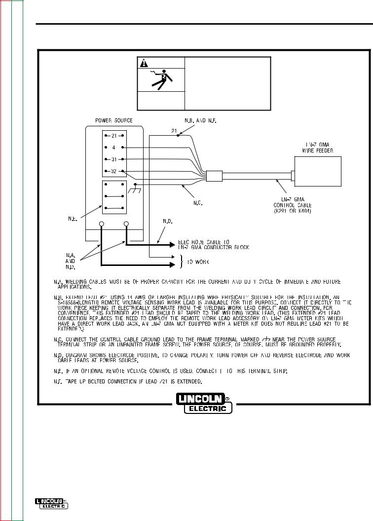
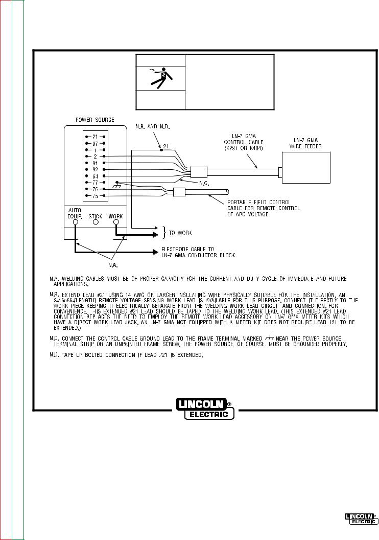
A.3 |
LN-7 GMA To DC-400, DC-250 and CV/CVI Power Sources With Terminal Strip - Connection |
|
|
|
|
Diagram |
|
|
|
|
|
|
|
|
A.4 |
LN-7 GMA To Pulsed Power 500 - Connection Diagram |
|
|
|
|
|
|
|
|
A.5 |
LN-7 GMA To CV/CVI Power Sources With 14 Pin Amphenol Connector - Connection Diagram |
|
|
|
|
|
|
|
|
A.6 |
LN-7 GMA To CV/CVI Power Sources With Twist-Mate Connector and 14 Pin Amphenol/Remote |
|
|
|
|
Control - Connection Diagram |
|
|
|
|
|
|
|
|
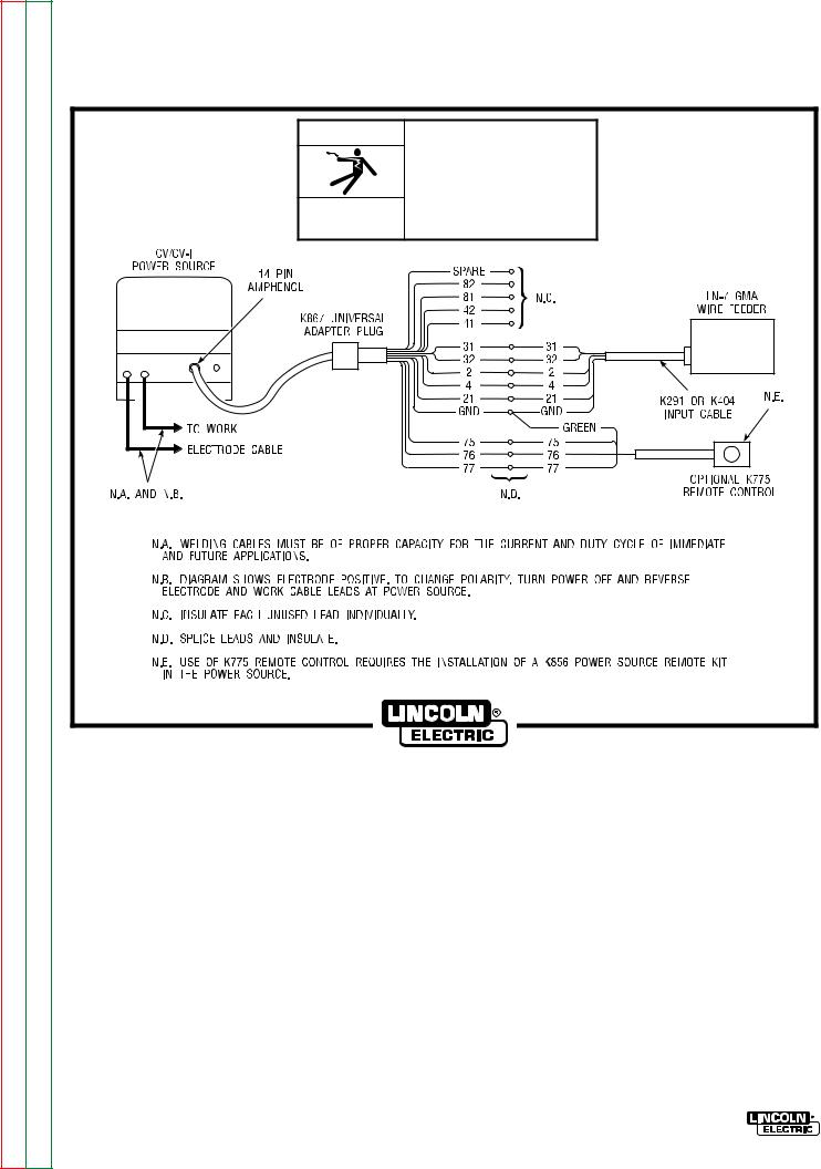
A.7 |
LN-7 GMA To CV/CVI Power Source (K867/K775) - Connection Diagram |
|
|
|
|
|
|
|
|
A.8 |
LN-7 GMA To R3S-250 or R3S-325 - Connection Diagram |
|
|
|
|
|
|
|
|
A.9 |
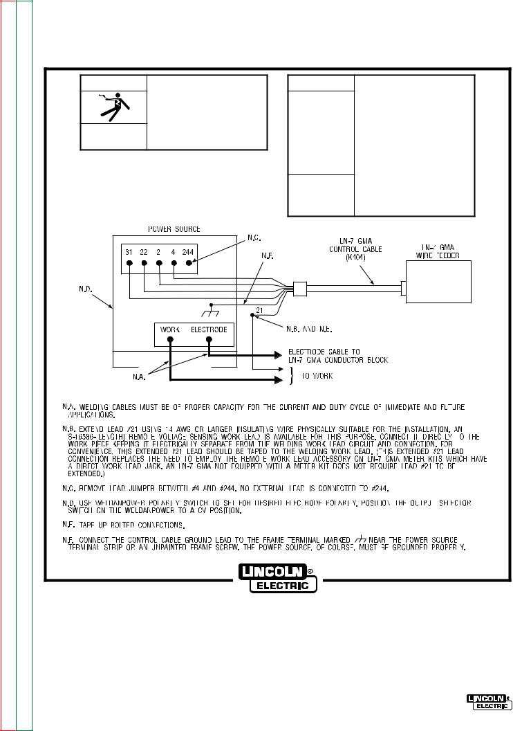
LN-7 GMA To SAM Motor Generator or Engine Welder - Connection Diagram |
|
|
|
|
|
|
|
|
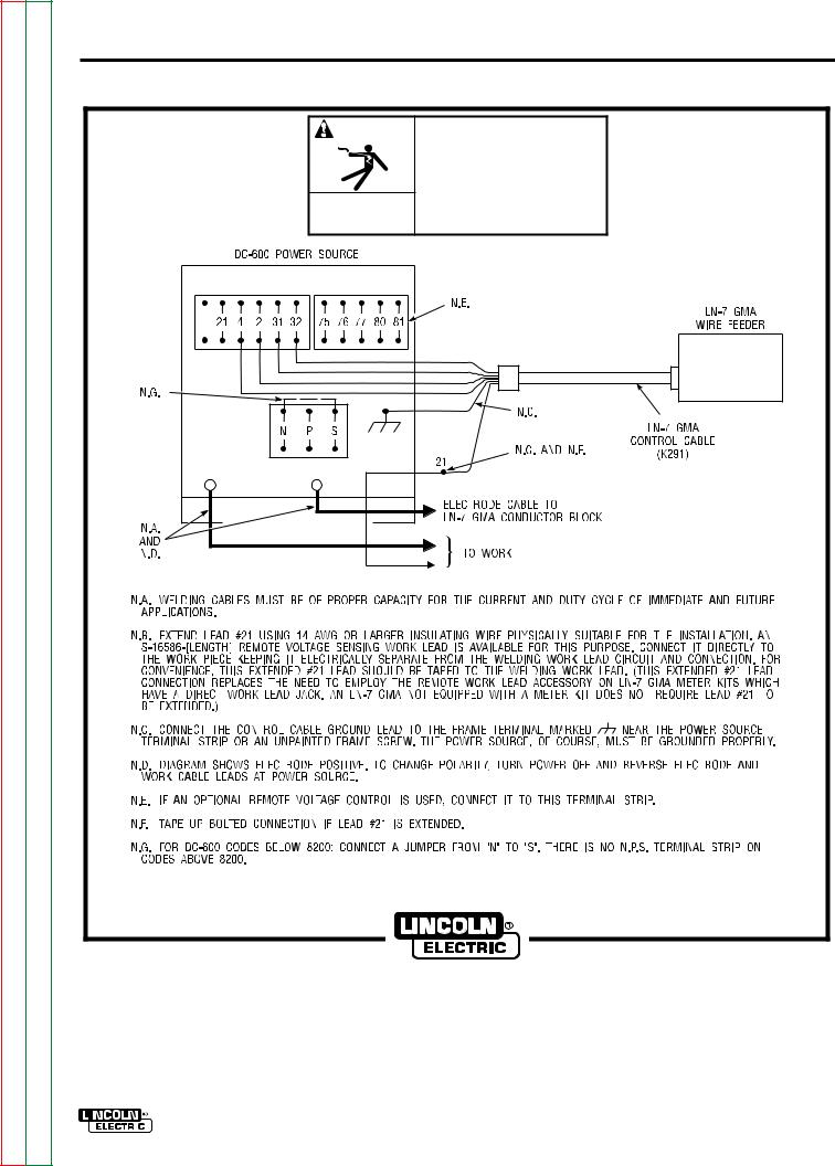
A.10 |
LN-7 GMA To DC-600 - Connection Diagram |
|
|
|
|
|
|
|
|
A.11 |
LN-7 GMA To R3S-400, 600, or 800 - Connection Diagram |
|
|
|
|
|
|
|
|
A.12 |
LN-7 GMA To Most Lincoln Motor Generators - Connection Diagram |
|
|
|
|
|
|
|
|
A.13 |
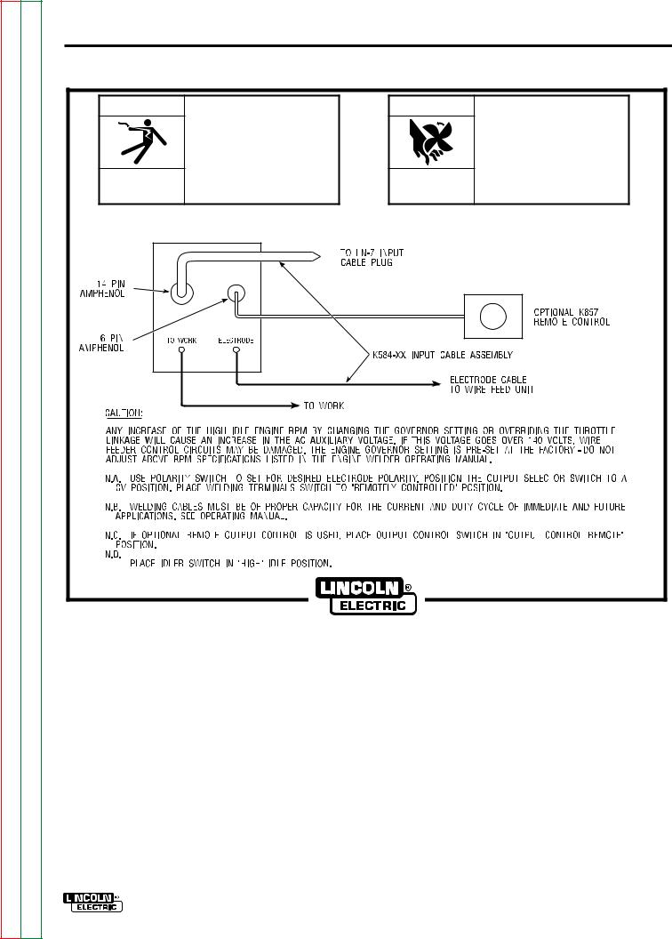
LN-7 GMA To WP250 or G9 PRO - Connection Diagram |
|
|
|
|
|
|
|
|
A.14 |
LN-7 |
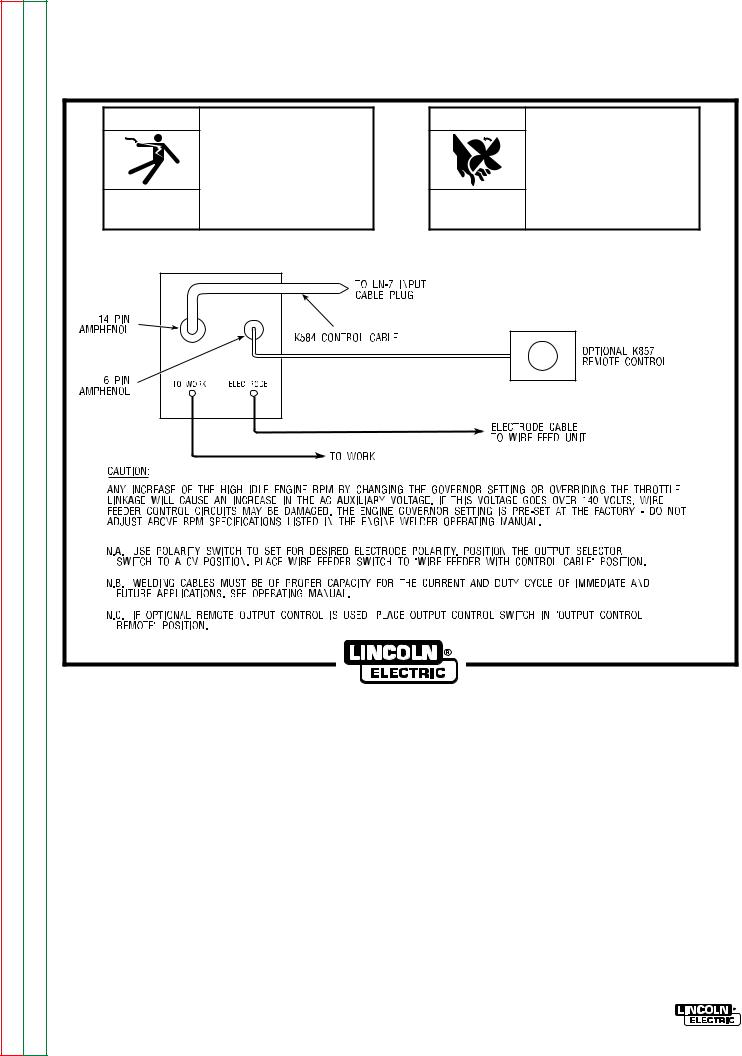
GMA To Ranger 9 - Connection Diagram |
|
|
|
|
|
|
|
A.15 |
LN-7 |
GMA To Ranger 10-LX - Connection Diagram |
|
|
|
|
|
|
|
A.16 |
LN-7 |
GMA To Power Sources With No Output Contactor - Connection Diagram |
|
|
|
|
|
|
|
A.17 |
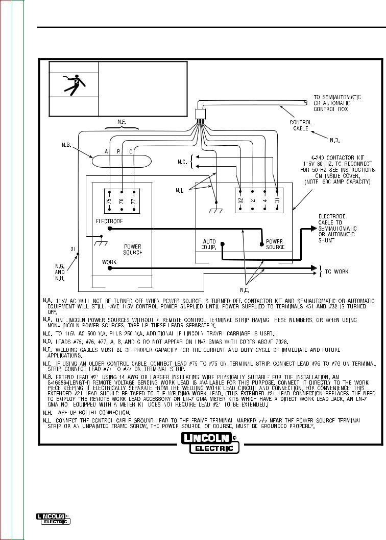
LN-7 |
GMA To Power Sources With Contactor and No Terminal Strip - Connection Diagram |
|
|
|
|
|
|
|
|
|
|
|
|
|
|
|
LN-7 GMA WIRE FEEDER
Return to Section TOC |
Return to Master TOC |
Return to Section TOC |
Return to Master TOC |
Return to Section TOC |
Return to Master TOC |
Return to Section TOC |
Return to Master TOC |
A-4 |
INSTALLATION |
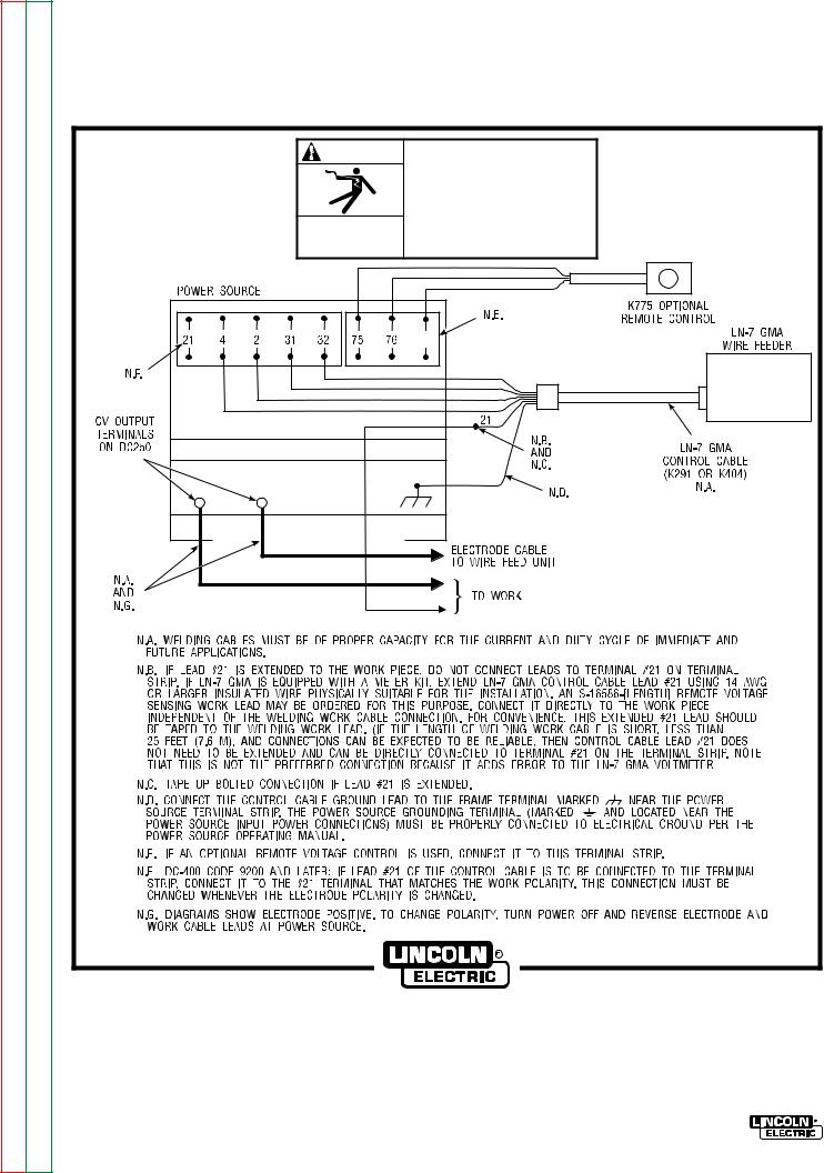
1.For K291 and K404 cables, connect the end of the control cable with the lugged leads to the power source. If lead #21 is extended to work, do not connect leads to terminal #21 on terminal strip. Include any jumpers called for on the connection diagram. Do not add any other jumpers or connections.
WARNING
Never operate a Lincoln power source that has a jumper from #2 to #4 on the terminal strip, or a power source without a contactor, with this wire feeder. To do so would defeat the purpose of the grounding lead protector circuit and could result in the overheating of the electrical ground circuit to the wire feeder.
2.For constant voltage power sources with an output contactor but no terminal strip or 14-pin control receptacle, see Figure A.14. For constant voltage power sources without an internal output contactor, and requiring a K240 Contactor Kit, see Figure A.13.
3.If input cables longer than the standard length must be used, K292 extension cables (50 ft/15.2 m) can be installed. These have polarized plugs on each end of the control cable and include a 4/0 (107 mm2) electrode cable. Install the extensions between the standard input cable and the wire feeder. Total input cable length should not exceed 400 ft (122 m). When using longer lengths of extension cables, it may be necessary to add parallel electrode cables to minimize the voltage drop in the cable.
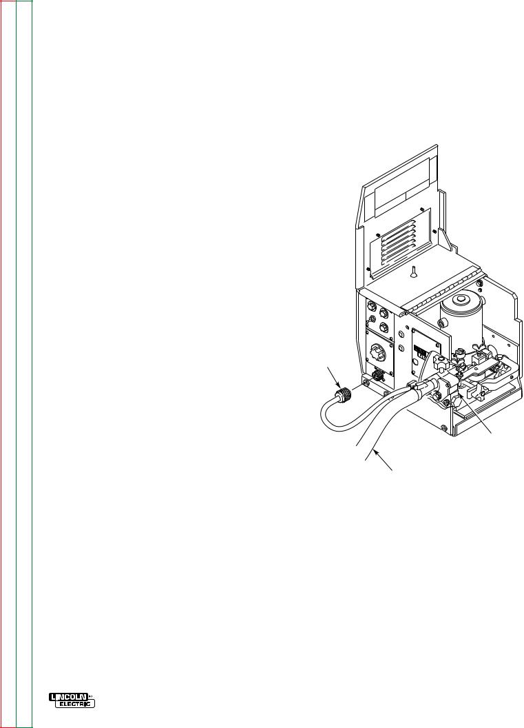
4.Referring to Figure A.1, route the end of the electrode cable through the large hole in the back panel of the LN-7 case. Connect the electrode cable to the brass conductor block on the front of the gearbox using the 1/2-13 x .75 bolt provided.
Be sure the cable is placed to allow easy access and clearance for the idle roll arm pressure adjustment and to allow the drive roll section cover to close.
FIGURE A.1 – INPUT CONTROL CABLE AND ELECTRODE CABLE CONNECTIONS.
CONDUCTOR
BLOCK
CONTROL
CABLE
ELECTRODE
LN-7 GMA WIRE FEEDER
Return to Section TOC |
Return to Master TOC |
Return to Section TOC |
Return to Master TOC |
Return to Section TOC |
Return to Master TOC |
Return to Section TOC |
Return to Master TOC |
|
INSTALLATION |
A-5 |
|
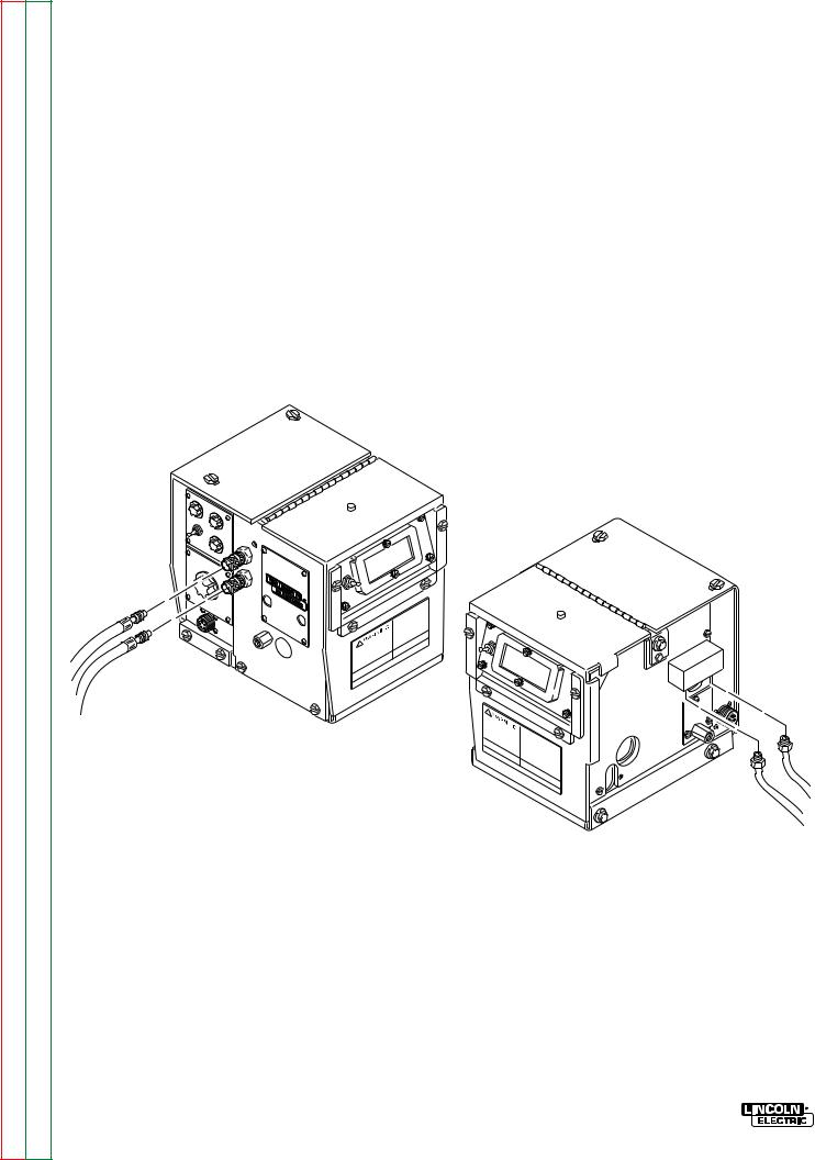
5. |
Connect the input control cable polarized |
clamp. Remove the screws holding the clamp to |
|
|
Amphenol plug into the mating 6-pin receptacle |
the base of the wire reel mounting assembly, put |
|
|
on the rear of the control section. |
the input cable assembly under the clamp and |
|
|
|
reinstall the screws. |
|
6. |
Referring to Figure A.2, install the input cable |
|
|
|
under the wire reel mounting stand strain relief |
|
|
FIGURE A.2 – STRAIN RELIEF CLAMP.
CONTROL
CABLE
STRAIN
RELIEF
CLAMP
ELECTRODE
CABLE
LN-7 GMA WIRE FEEDER
Return to Section TOC |
Return to Master TOC |
Return to Section TOC |
Return to Master TOC |
Return to Section TOC |
Return to Master TOC |
Return to Section TOC |
Return to Master TOC |
A-6 |
INSTALLATION |
FIGURE A.3 – LN-7 GMA TO DC-400, DC-250 AND CV/CVI POWER SOURCES WITH
TERMINAL STRIP - CONNECTION DIAGRAM.
WARNING TURN INPUT POWER OFF
BEFORE CONNECTING THE
LN-7 GMA WIRE FEEDER.
|
ELECTRIC |
|
SHOCK |
|
CAN KILL |
|
77 |
– |
+ |
CLEVELAND, OHIO U.S.A
LN-7 GMA WIRE FEEDER
Return to Section TOC |
Return to Master TOC |
Return to Section TOC |
Return to Master TOC |
Return to Section TOC |
Return to Master TOC |
Return to Section TOC |
Return to Master TOC |
|
|
|
|
|
|
|
|
|
|
|
|
|
|
|
|
|
|
INSTALLATION |
A-7 |
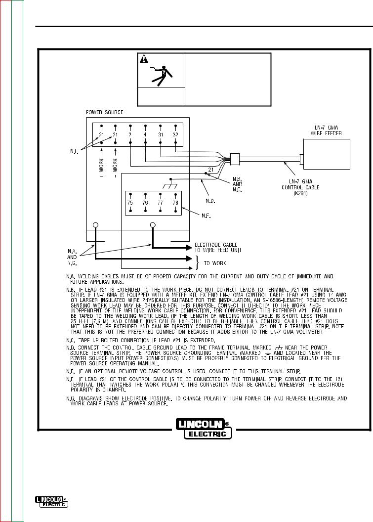
FIGURE A.4 – LN-7 GMA TO PULSED POWER 500 - CONNECTION DIAGRAM.
WARNING |
TURN INPUT POWER OFF |
|
BEFORE CONNECTING THE |
|
|
|
LN-7 GMA WIRE FEEDER. |
|
ELECTRIC |
|
SHOCK |
|
CAN KILL |
– |
+ |
CLEVELAND, OHIO U.S.A
LN-7 GMA WIRE FEEDER
Return to Section TOC |
Return to Master TOC |
Return to Section TOC |
Return to Master TOC |
Return to Section TOC |
Return to Master TOC |
Return to Section TOC |
Return to Master TOC |
A-8 |
INSTALLATION |
FIGURE A.5 – LN-7 GMA TO CV/CVI POWER SOURCES WITH 14 PIN AMPHENOL
CONNECTOR - CONNECTION DIAGRAM.
 WARNING
ELECTRIC
SHOCK
CAN KILL
TURN INPUT POWER OFF BEFORE CONNECTING THE LN-7 GMA WIRE FEEDER.
+ |
– |
CLEVELAND, OHIO U.S.A
LN-7 GMA WIRE FEEDER
Return to Section TOC |
Return to Master TOC |
Return to Section TOC |
Return to Master TOC |
Return to Section TOC |
Return to Master TOC |
Return to Section TOC |
Return to Master TOC |
|
|
|
|
|
|
|
|
|
|
|
|
|
|
|
|
|
|
INSTALLATION |
A-9 |
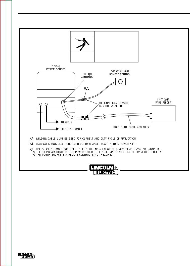
FIGURE A.6 – LN-7 GMA TO CV/CVI POWER SOURCES WITH TWIST-MATE CONNECTOR AND 14 PIN AMPHENOL/REMOTE CONTROL - CONNECTION DIAGRAM.
 WARNING
ELECTRIC
SHOCK
CAN KILL
 TURN OFF INPUT POWER TO THE WELDING POWER SOURCE USING THE DISCONNECT SWITCH AT THE FUSE BOX BEFORE CONNECTING THE WIRE FEEDER.
 ONLY QUALIFIED PERSONS SHOULD INSTALL, USE, OR SERVICE THIS MACHINE.
+ –
CLEVELAND, OHIO U.S.A
LN-7 GMA WIRE FEEDER
Return to Section TOC |
Return to Master TOC |
Return to Section TOC |
Return to Master TOC |
Return to Section TOC |
Return to Master TOC |
Return to Section TOC |
Return to Master TOC |
A-10 |
INSTALLATION |
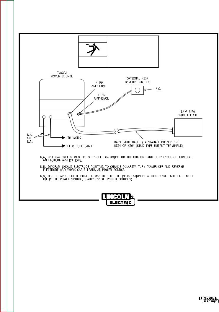
FIGURE A.7 – LN-7 GMA TO CV/CVI POWER SOURCE (K867/K775) - CONNECTION DIAGRAM.
 WARNING
ELECTRIC
SHOCK
CAN KILL
TURN INPUT POWER OFF BEFORE CONNECTING THE LN-7 GMA WIRE FEEDER.
+ –
CLEVELAND, OHIO U.S.A
LN-7 GMA WIRE FEEDER
Return to Section TOC |
Return to Master TOC |
Return to Section TOC |
Return to Master TOC |
Return to Section TOC |
Return to Master TOC |
Return to Section TOC |
Return to Master TOC |
|
|
|
|
|
|
|
|
|
|
|
|
|
|
|
|
|
|
INSTALLATION |
A-11 |
FIGURE A.8 – LN-7 GMA TO R3S-250 OR R3S-325 - CONNECTION DIAGRAM.
|
WARNING |
|
ELECTRIC |
|
SHOCK |
|
CAN KILL |
– |
+ |
TURN INPUT POWER OFF BEFORE CONNECTING THE LN-7 GMA WIRE FEEDER.
CLEVELAND, OHIO U.S.A
LN-7 GMA WIRE FEEDER
Return to Section TOC |
Return to Master TOC |
Return to Section TOC |
Return to Master TOC |
Return to Section TOC |
Return to Master TOC |
Return to Section TOC |
Return to Master TOC |
A-12 |
INSTALLATION |
FIGURE A.9 – LN-7 GMA TO SAM MOTOR GENERATOR OR ENGINE WELDER - CONNECTION DIAGRAM.
 WARNING
ELECTRIC
SHOCK
CAN KILL
TURN INPUT POWER OFF BEFORE CONNECTING THE LN-7 GMA WIRE FEEDER.
CLEVELAND, OHIO U.S.A
LN-7 GMA WIRE FEEDER
Return to Section TOC |
Return to Master TOC |
Return to Section TOC |
Return to Master TOC |
Return to Section TOC |
Return to Master TOC |
Return to Section TOC |
Return to Master TOC |
|
|
|
|
|
|
|
|
|
|
|
|
|
|
|
|
|
|
INSTALLATION |
A-13 |
FIGURE A.10 – LN-7 GMA TO DC-600 - CONNECTION DIAGRAM.
WARNING |
TURN INPUT POWER OFF |
|
BEFORE CONNECTING THE |
|
|
|
LN-7 GMA WIRE FEEDER. |
|
ELECTRIC |
|
SHOCK |
|
CAN KILL |
– |
+ |
CLEVELAND, OHIO U.S.A
LN-7 GMA WIRE FEEDER

Return to Section TOC |
Return to Master TOC |
Return to Section TOC |
Return to Master TOC |
Return to Section TOC |
Return to Master TOC |
Return to Section TOC |
Return to Master TOC |
A-14 |
INSTALLATION |
FIGURE A.11 – LN-7 GMA TO R3S-400, 600, OR 800 - CONNECTION DIAGRAM.
WARNING |
TURN INPUT POWER OFF |
|
BEFORE CONNECTING THE |
|
|
|
LN-7 GMA WIRE FEEDER. |
ELECTRIC |
SHOCK |
CAN KILL |
CLEVELAND, OHIO U.S.A
LN-7 GMA WIRE FEEDER
Return to Section TOC |
Return to Master TOC |
Return to Section TOC |
Return to Master TOC |
Return to Section TOC |
Return to Master TOC |
Return to Section TOC |
Return to Master TOC |
|
|
|
|
|
|
|
INSTALLATION |
A-15 |
FIGURE A.12 – LN-7 GMA TO MOST LINCOLN MOTOR GENERATORS - CONNECTION DIAGRAM.
 WARNING
ELECTRIC
SHOCK
CAN KILL
TURN INPUT POWER OFF BEFORE CONNECTING THE LN-7 GMA WIRE FEEDER.
32
CLEVELAND, OHIO U.S.A
LN-7 GMA WIRE FEEDER
Return to Section TOC |
Return to Master TOC |
Return to Section TOC |
Return to Master TOC |
Return to Section TOC |
Return to Master TOC |
Return to Section TOC |
Return to Master TOC |
A-16 |
INSTALLATION |
FIGURE A.13 – LN-7 GMA TO WP250 OR G9 PRO - CONNECTION DIAGRAM.
 WARNING
ELECTRIC
SHOCK
CAN KILL
TURN INPUT POWER OFF BEFORE CONNECTING THE LN-7 GMA WIRE FEEDER.
 CAUTION
AUXILIARY VOLTAGE MUST NOT EXCEED 140 VOLTS.
LN-7 GMA TO WP250 G9 PRO: ANY INCREASE OF THE HIGH IDLE ENGINE RPM BY CHANGING THE GOVERNOR SETTING OR OVERRIDING THE THROTTLE LINKAGE WILL CAUSE AN INCREASE IN THE AC AUXILIARY VOLTAGE. IF THIS VOLTAGE GOES ABOVE 140 VOLTS, THE LN-7 GMA CONTROL CIRCUIT WILL BE DAMAGED. THE ENGINE GOVERNOR SETTING IS PRE-SET AT THE FACTORY - DO NOT ADJUST ABOVE RPM SPECIFICATIONS LISTED IN ENGINE WELDER OPERATING MANUAL.
CLEVELAND, OHIO U.S.A
LN-7 GMA WIRE FEEDER
Return to Section TOC |
Return to Master TOC |
Return to Section TOC |
Return to Master TOC |
Return to Section TOC |
Return to Master TOC |
Return to Section TOC |
Return to Master TOC |
|
|
|
|
|
|
|
INSTALLATION |
A-17 |
FIGURE A.14 – LN-7 GMA TO RANGER 9 – CONNECTION DIAGRAM.
 WARNING
ELECTRIC
SHOCK
CAN KILL
 DO NOT OPERATE WITH PANELS OPEN.
 DISCONNECT NEGATIVE (-) BATTERY LEAD BEFORE SERVICING.
 DO NOT TOUCH ELECTRICALLY LIVE PARTS.
 WARNING
MOVING
PARTS
CAN INJURE
 KEEP GUARDS IN PLACE.
 KEEP AWAY FROM MOVING PARTS.
 ONLY QUALIFIED PERSONS SHOULD INSTALL, USE, OR SERVICE THIS MACHINE.
CLEVELAND, OHIO U.S.A
LN-7 GMA WIRE FEEDER
Return to Section TOC |
Return to Master TOC |
Return to Section TOC |
Return to Master TOC |
Return to Section TOC |
Return to Master TOC |
Return to Section TOC |
Return to Master TOC |
A-18 |
INSTALLATION |
FIGURE A.15 – LN-7 GMA TO RANGER 10-LX – CONNECTION DIAGRAM.
 WARNING
ELECTRIC
SHOCK
CAN KILL
 DO NOT OPERATE WITH PANELS OPEN.
 DISCONNECT NEGATIVE (-) BATTERY LEAD BEFORE SERVICING.
 DO NOT TOUCH ELECTRICALLY LIVE PARTS.
 WARNING
MOVING
PARTS
CAN INJURE
 KEEP GUARDS IN PLACE.
 KEEP AWAY FROM MOVING PARTS.
 ONLY QUALIFIED PERSONS SHOULD INSTALL, USE, OR SERVICE THIS MACHINE.
CLEVELAND, OHIO U.S.A
LN-7 GMA WIRE FEEDER
Return to Section TOC |
Return to Master TOC |
Return to Section TOC |
Return to Master TOC |
Return to Section TOC |
Return to Master TOC |
Return to Section TOC |
Return to Master TOC |
|
|
|
|
|
|
|
INSTALLATION |
A-19 |
FIGURE A.16 – LN-7 GMA TO POWER SOURCES WITH NO OUTPUT
CONTACTOR - CONNECTION DIAGRAM.
 WARNING
ELECTRIC
SHOCK
CAN KILL
TURN INPUT POWER OFF BEFORE CONNECTING THE LN-7 GMA WIRE FEEDER.
CLEVELAND, OHIO U.S.A
LN-7 GMA WIRE FEEDER

Return to Section TOC |
Return to Master TOC |
Return to Section TOC |
Return to Master TOC |
Return to Section TOC |
Return to Master TOC |
Return to Section TOC |
Return to Master TOC |
A-20 |
INSTALLATION |
FIGURE A.17 – LN-7 GMA TO POWER SOURCES WITH CONTACTOR AND NO TERMINAL
STRIP - CONNECTION DIAGRAM.
 WARNING
ELECTRIC |
SHOCK |
CAN KILL |
TURN INPUT POWER OFF BEFORE CONNECTING THE LN-7 GMA WIRE FEEDER.
CLEVELAND, OHIO U.S.A
LN-7 GMA WIRE FEEDER
Return to Section TOC |
Return to Master TOC |
Return to Section TOC |
Return to Master TOC |
Return to Section TOC |
Return to Master TOC |
Return to Section TOC |
Return to Master TOC |
INSTALLATION |
A-21 |
WORK CABLE
Connect a work lead of sufficient size and length (Table A.2) between the proper output stud on the power source and the work. Be sure the connection to the work makes tight metal-to-metal electrical contact. Poor work lead connections can result in the grounding lead protector being activated.
TABLE A.2 – WORK LEAD SPECIFICATIONS
|
Copper Work Cable Size, AWG |
||
|
|
|
|
Current 60% |
Up To 50 Ft |
50 Ft-100 Ft |
|
Duty Cycle |
(15.2 m2) |
(15.2-30.4 m2) |
|
300 Amps |
0 (53 mm2) |
00 (67 mm2) |
|
400 Amps |
00 (67 mm2) |
000 |
(85 mm2) |
500 Amps |
00 (67 mm2) |
000 |
(85 mm2) |
600 Amps |
000 (85 mm2) |
0000 |
(107 mm2) |
Connect the control cable amphenol plug into the mating 5-cavity receptacle on the front of the control section below the nameplate.
If using the K489-1 Fast-Mate Adapter, install per the S19389 instructions included with the kit.
FIGURE A.18 – GUN CABLE CONNECTIONS.
GUN AND CABLE ASSEMBLIES
The LN-7 GMA can be used with several guns. In most cases, Lincoln guns and cables are shipped assembled, ready to weld. Use the gun and cable assembly for the electrode type (solid, Outershield , or Innershield) and electrode size to be used. Refer to the Accessories Section for different gun types.
GUN CABLE CONNECTIONS
Lay the cable out straight. Insert the connector on the welding conductor cable through the large hole in the front panel of the LN-7 GMA and into the brass conductor block on the front of the gearbox. Refer to Figure A.18. Make sure it is all the way in and tighten the hand wheel. Keep this connection clean and bright.
AMPHENOL CONNECTOR
GUN CABLE ASSEMBLY
CONDUCTOR
BLOCK
LN-7 GMA WIRE FEEDER
Return to Section TOC |
Return to Master TOC |
Return to Section TOC |
Return to Master TOC |
Return to Section TOC |
Return to Master TOC |
Return to Section TOC |
Return to Master TOC |
A-22 |
INSTALLATION |
WATER CONNECTIONS
(FOR WATER COOLED GUNS)
The LN-7 GMA must have a K527 Water Solenoid Kit installed (see the Accessories Section). The K440-1 LN-7 GMA model already has a water solenoid installed. Refer to Figure A.19 and perform the following steps:
NOTE: If not using a Lincoln water cooler (such as the K877-1), and if your water cooling device is not designed for use with a waterline solenoid valve, you may remove the solenoid and screw the male fitting (after applying sealant) directly into the brass manifold block.
1.Using male 5/8-18 UNF left-hand thread fittings, connect appropriate water hoses to the coolant inlet and outlet on the back of the LN-7 GMA. Connect the other ends of these hoses to the appropriate ports on your water cooling units.
2.In the event the water line fittings on your water cooled gun are incompatible with the female quick connects on the front of the LN-7 GMA, male quick connects are provided for installation on 3/16 in. I.D. hose (customer to provide appropriate clamps). The feeder connectors self seal when disconnected.
FIGURE A.19 – WATER CONNECTIONS.
FRONT
BACK
LN-7 GMA WIRE FEEDER
Return to Section TOC |
Return to Master TOC |
Return to Section TOC |
Return to Master TOC |
Return to Section TOC |
Return to Master TOC |
Return to Section TOC |
Return to Master TOC |
INSTALLATION |
A-23 |
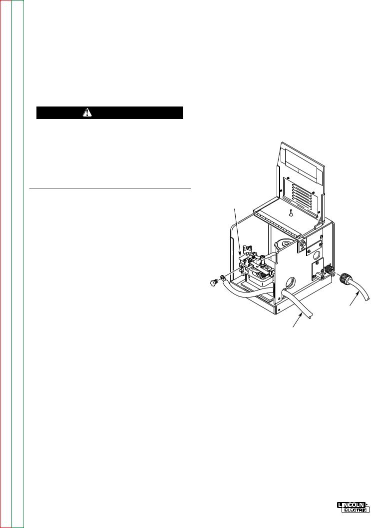
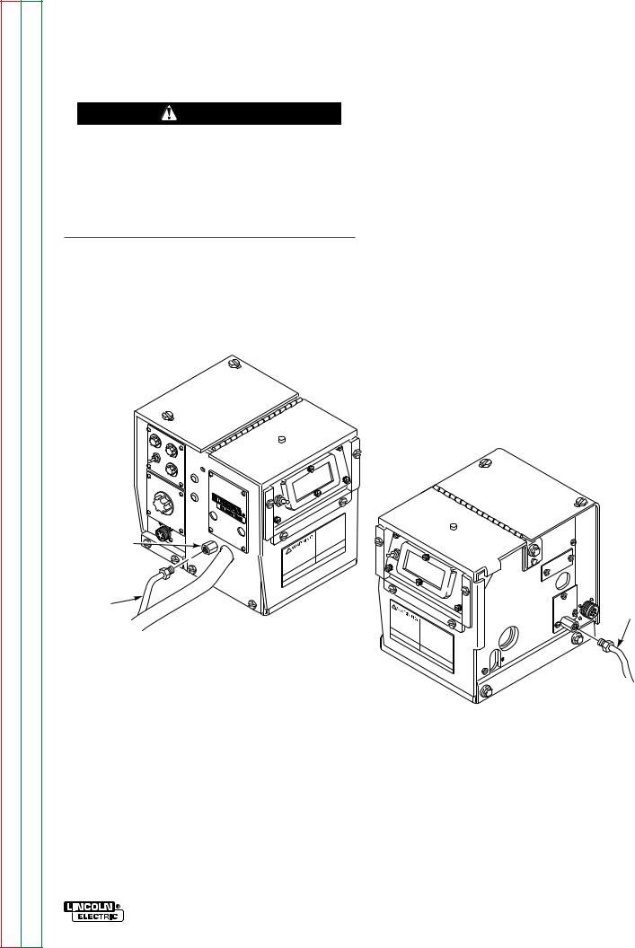
SHIELDING GAS HOOKUP
WARNING
Gas under pressure is explosive. Always keep gas cylinders in an upright position and to the undercarriage or a stationary support. See American National Standard Z-49.1, “Safety In Welding And Cutting”, published by the American Welding Society.
Customer must provide a cylinder of shielding gas, a pressure regulator, a flow control valve, and a hose from the flow valve to the gas inlet fitting of the LN-7
GMA or the K494 Gas Solenoid Valve Kit installed on the LN-7 GMA. Install per Figure A.20 and the following:
1.Connect the supply hose from the gas cylinder flow valve outlet to the 5/8-18 female inert gas fitting on the back panel of the LN-7 GMA.
2.Install the barbed fitting and union nut to the 5/8-18 female inert gas fitting on the front of the LN-7 GMA. Connect 3/16 in. (4.8 mm) I.D. gas hose from the gun to the barbed fitting.
When the gun is to be removed, this fitting can be easily detached by loosening the union nut.
FIGURE A.20 – SHIELDING GAS HOOKUP.
INERT |
|
GAS |
|
FITTING |
|
|
GAS |
GAS |
SUPPLY |
HOSE |
HOSE |
LN-7 GMA WIRE FEEDER

Return to Section TOC |
Return to Section TOC |
Return to Section TOC |
Return to Section TOC |
|
|
|
|
Return to Master TOC |
Return to Master TOC |
Return to Master TOC |
Return to Master TOC |
|
|
|
|
GMA 7-LN |
|
|
24-A |
FEEDER WIRE |
|
|
|
NOTES
Loading...