


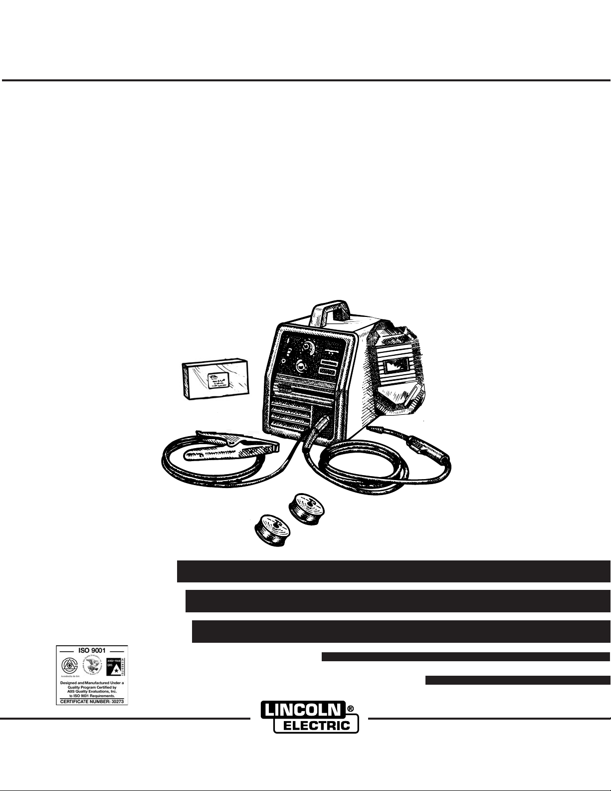
Pro-MIG 140
Pro-MIG 140
MANUAL DEL OPERADOR
OPERATOR’S MANUAL
IM884
April, 2006
For use with machine Code Number:
Para el uso con número del código automático:
Pro-MIG™ 140
• Sales and Service through Subsidiaries and Distributors Worldwide •
TEL: 216.481.8100 FAX: 216.486.1751 WEB SITE: www.lincolnelectric.com
• World's Leader in Welding and Cutting Products •
Copyright © 2006 Lincoln Global Inc.
™
Safety Depends on You
Lincoln arc welding and cutting equipment
is designed and built with safety in mind.
However, your overall safety can be
increased by proper installation ... and
thoughtful operation on your part. DO NOT
INSTALL, OPERATE OR REPAIR THIS
EQUIPMENT WITHOUT READING THE
OPERATORS MANUAL WHICH IS PRO-
VIDED WITH YOUR MACHINE AND THE
SAFETY PRECAUTIONS CONTAINED
THROUGHOUT. And, most importantly,
think before you act and be careful.
La seguridad depende de usted
El equipo de soldadura por arco y corte de
Lincoln está diseñado y construido teniendo
en mente la seguridad. Sin embargo, la
seguridad general puede ser mejor si instala
y opera la máquina adecuadamente.
NO
INSTALE, NO PONGA EN FUN-
CIONAMIENTO NI REPARE ESTE EQUIPO
SIN LA LECTURA DEL MANUAL DE LOS
OPERADORES QUE SE PROPORCIONA
CON SU MÁQUINA Y LAS MEDIDAS DE
SEGURIDAD CONTENIDAS EN EL MISMO.
Lo más importante, piense antes de actuar
y tenga cuidado.
}
11288
RETURN TO MAIN MENU
i
SAFETY
i
Mar ‘95
ARC WELDING CAN BE HAZARDOUS. PROTECT YOURSELF AND OTHERS FROM POSSIBLE SERIOUS INJURY OR DEATH.
KEEP CHILDREN AWAY. PACEMAKER WEARERS SHOULD CONSULT WITH THEIR DOCTOR BEFORE OPERATING.
Read and understand the following safety highlights. For additional safety information, it is strongly recommend-
ed that you purchase a copy of “Safety in Welding & Cutting - ANSI Standard Z49.1” from the American Welding
Society, P.O. Box 351040, Miami, Florida 33135 or CSA Standard W117.2-1974. A Free copy of “Arc Welding
Safety” booklet E205 is available from the Lincoln Electric Company, 22801 St. Clair Avenue, Cleveland, Ohio
44117-1199.
BE SURE THAT ALL INSTALLATION, OPERATION, MAINTENANCE AND REPAIR PROCEDURES ARE
PERFORMED ONLY BY QUALIFIED INDIVIDUALS.
WARNING
ARC RAYS can burn.
2.a. Use a shield with the proper filter
and cover plates to protect your
eyes from sparks and the rays of
the arc when welding or observing
open arc welding. Headshield and
filter lens should conform to ANSI
Z87. I standards.
2.b.Use suitable clothing made from durable flame-
resistant material to protect your skin and that of
your helpers from the arc rays.
2.c. Protect other nearby personnel with suitable,
non-flammable screening and/or warn them not
to watch the arc nor expose themselves to the
arc rays or to hot spatter or metal.
FOR ELECTRICALLY
powered equipment.
1.a. Turn off input power using the dis-
connect switch at the fuse box
before working on the equipment.
1.b.Install equipment in accordance with the U.S.
National Electrical Code, all local codes and the
manufacturer’s recommendations.
1.c. Ground the equipment in accordance with the
U.S. National Electrical Code and the manufac-
turer’s recommendations.
ELECTRIC AND MAGNETIC
FIELDS may be dangerous
3.a. Electric current flowing through
any conductor causes localized
Electric and Magnetic Fields
(EMF). Welding current creates
EMF fields around welding cables
and weldingmachines
3.b.EMF fields may interfere with some pacemak-
ers, and welders having a pacemaker should
consult their physician before welding.
3.c. Exposure to EMF fields in welding may have
other health effects which are now not known.
3.d.All welders should use the following procedures
in order to minimize exposure to EMF fields from
the welding circuit:
3.d.1. Route the electrode and work cables together
- Secure them with tape when possible.
3.d.2. Never coil the electrode lead around your
body.
3.d.3. Do not place your body between the electrode
and work cables. If the electrode cable is on
your right side, the work cable should also be
on your right side.
3.d.4. Connect the work cable to the workpiece as
close as possible to the area being welded.
3.d.5. Do not work next to welding power source.

ii
SAFETY
ii
WELDING SPARKS can
cause fire or explosion.
4.a.
Remove fire hazards from the
welding area.
If this is not possi-
ble, cover them to prevent the
welding sparks from starting a fire.
Remember that welding sparks
and hot materials from welding
can easily go through small cracks
and openings to adjacent areas.
Avoid welding near hydraulic lines.
Have a fire extinguisher readily
available.
4.b.Where compressed gases are to be used at the
job site, special precautions should be used to
prevent hazardous situations. Refer to “Safety in
Welding and Cutting” (ANSI Standard Z49.1)
and the operating information for the equipment
being used.
4.c. When not welding, make certain no part of the
electrode circuit is touching the work or ground.
Accidental contact can cause overheating and
create a fire hazard.
4.d.Do not heat, cut or weld tanks, drums or con-
tainers until the
proper steps have been taken to
insure that such procedures
will not cause flam-
mable or toxic vapors from substances inside.
They can cause an explosion even
though
they
have been “cleaned”. For information, purchase
“Recommended Safe Practices for the
Preparation
for Welding and Cutting of
Containers and Piping That Have Held
Hazardous Substances”, AWS F4.1 from the
American Welding Society
(see address above).
4.e.Vent hollow castings or containers before heat-
ing, cutting or welding. They may explode.
4.f.
Sparks and spatter are thrown from the welding
arc. Wear oil
free protective garments such as
leather gloves, heavy shirt, cuffless trousers, high
shoes and a cap over your hair. Wear ear plugs
when welding out of position or in confined
places. Always wear safety glasses with side
shields when in a welding area.
4.g.Connect the work cable to the work as close to
the welding area as practical. Work cables con-
nected to the building framework or other loca-
tions away from the welding area increase the
possibility of the welding current passing through
lifting chains, crane cables or other alternate cir-
cuits. This can create fire hazards or overheat
lifting chains or cables until they fail.
ELECTRIC SHOCK can kill.
5.a.The electrode and work (or ground)
circuits are electrically “hot” when the
welder is on. Do not touch these
“hot” parts with your bare skin or wet
clothing. Wear dry, hole-free gloves
to insulate hands.
5.b. Insulate yourself from work and ground using dry
insulation. Make certain the insulation is large
enough to cover your full area of physical contact
with work and ground.
In addition to the normal safety precautions, if
welding must be performed under electrically
hazardous conditions (in damp locations or
while wearing wet clothing; on metal structures
such as floors, gratings or scaffolds; when in
cramped positions such as sitting, kneeling or
lying, if there is a high risk of unavoidable or
accidental contact with the workpiece or
ground) use the following equipment:
• Semiautomatic DC Constant Voltage (Wire)
Welder.
• DC Manual (Stick) Welder.
• AC Welder with Reduced Voltage Control.
5.c. In semiautomatic or automatic wire welding, the
electrode, electrode reel, welding head, nozzle or
semiautomatic welding gun are also electrically
“hot”.
5.d. Always be sure the work cable makes a good elec-
trical connection with the metal being welded. The
connection should be as close as possible to the
area being welded.
5.e. Ground the work or metal to be welded to a good
electrical (earth) ground.
5.f. Maintain the electrode holder, work clamp, welding
cable and welding machine in good, safe operating
condition. Replace damaged insulation.
5.g. Never dip the electrode in water for cooling.
5.h. Never simultaneously touch electrically “hot” parts
of electrode holders connected to two welders
because voltage between the two can be the total
of the open circuit voltage of both welders.
5.i. When working above floor level, use a safety belt
to protect yourself from a fall should you get a
shock.
5.j. Also see Items 4.c. and 1.
MAR95

iii
SAFETY
iii
FUMES AND GASES
can be dangerous.
6.a.Welding may produce fumes and gases haz-
ardous to health. Avoid breathing these fumes
and gases.When welding, keep your head out of
the fume. Use enough
ventilation and/or exhaust
at the arc to keep
fumes and gases away from
the breathing zone. When welding with elec-
trodes which require special ventilation such
as stainless or hard facing (see instructions
on container or MSDS) or on lead or cadmi-
um plated steel and other metals or coatings
which produce highly toxic fumes, keep
exposure as low as possible and below
Threshold Limit Values (TLV) using local
exhaust or mechanical ventilation. In con-
fined spaces or in some circumstances, out-
doors, a respirator may be required.
Additional precautions are also required
when welding on galvanized steel.
6.b.
Do not weld in locations near chlorinated hydro-
carbon
vapors coming from degreasing, clean-
ing or spraying operations. The heat and rays
of the arc can react with solvent vapors
to
form
phosgene, a highly toxic gas, and other irri-
tating products.
6.c.Shielding gases used for arc welding can dis-
place air and cause injury or death. Always use
enough ventilation, especially in confined areas,
to insure breathing air is safe.
6.d.Read and understand the manufacturer’s
instructions for this equipment and the consum-
ables to be used, including the material safety
data sheet (MSDS) and follow your employer’s
safety practices. MSDS forms are available from
your welding distributor or from the manufactur-
er.
MAR95
CYLINDER may explode if
damaged.
7.a. Use only compressed gas cylinders containing
the correct shielding gas for the process used
and properly operating regulators designed for
the gas and pressure used. All hoses, fittings,
etc. should be suitable for the application and
maintained in good condition.
7.b.Always keep cylinders in an upright position
securely
chained to an undercarriage or fixed support.
7.c. Cylinders should be located:
•Away from areas where they may be struck or
subjected to physical damage.
•A safe distance from arc welding or cutting
operations and any other source of heat,
sparks, or flame.
7.d.Never allow the electrode, electrode holder or
any other electrically “hot” parts to touch a cylin-
der.
7.e.Keep your head and face away from the cylinder
valve outlet when opening the cylinder valve.
7.f. Valve protection caps should always be in place
and hand tight except when the cylinder is in
use or connected for use.
7.g.Read and follow the instructions on compressed
gas cylinders, associated equipment, and CGA
publication P-l, “Precautions for Safe Handling
of Compressed Gases in Cylinders,” available
from the Compressed Gas Association 1235
Jefferson Davis Highway, Arlington, VA 22202.

iviv
Thank You
for selecting a QUALITY product by Lincoln Electric. We want you
to take pride in operating this Lincoln Electric Company product
••• as much pride as we have in bringing this product to you!
Read this Operators Manual completely before attempting to use this equipment. Save this manual and keep it
handy for quick reference. Pay particular attention to the safety instructions we have provided for your protection.
The level of seriousness to be applied to each is explained below:
WARNING
This statement appears where the information must be followed exactly to avoid serious personal injury or
loss of life.
This statement appears where the information must be followed to avoid minor personal injury or damage to
this equipment.
CAUTION
Please Examine Carton and Equipment For Damage Immediately
When this equipment is shipped, title passes to the purchaser upon receipt by the carrier. Consequently, Claims
for material damaged in shipment must be made by the purchaser against the transportation company at the
time the shipment is received.
Please record your equipment identification information below for future reference. This information can be
found on your machine nameplate.
Product _________________________________________________________________________________
Model Number ___________________________________________________________________________
Code Number or Date Code_________________________________________________________________
Serial Number____________________________________________________________________________
Date Purchased___________________________________________________________________________
Where Purchased_________________________________________________________________________
Whenever you request replacement parts or information on this equipment, always supply the information you
have recorded above. The code number is especially important when identifying the correct replacement parts.
On-Line
Product Registration
- Register your machine with Lincoln Electric either via fax or over the Internet.
• For faxing: Complete the form on the back of the warranty statement included in the literature packet
accompanying this machine and fax the form per the instructions printed on it.
• For On-Line Registration: Go to our
WEB SITE at www.lincolnelectric.com. Choose “Quick Links” and then
“Product Registration”. Please complete the form and submit your registration.

v
v
TABLE OF CONTENTS FOR ALL SECTIONS
Page
Installation .......................................................................................................Section A
Technical Specifications ........................................................................................A-1
Identify and Locate Components...........................................................................A-2
Select Suitable Location ........................................................................................A-3
Output Connections...............................................................................................A-3
Input Connections..................................................................................................A-6
Code Requirements ..............................................................................................A-6
________________________________________________________________________
Operation .........................................................................................................Section B
Safety Precautions ................................................................................................B-1
General Description...............................................................................................B-1
Design Features ....................................................................................................B-1
Welding Capability.................................................................................................B-2
Limitations..............................................................................................................B-2
Controls and Settings ............................................................................................B-2
Welding Operations ...............................................................................................B-3
Overload Protection...............................................................................................B-6
Application Chart ...................................................................................................B-7
________________________________________________________________________
Accessories.....................................................................................................Section C
Accessories ...........................................................................................................C-1
Replacement Parts................................................................................................C-2
________________________________________________________________________
Maintenance ....................................................................................................Section D
Safety Precautions ................................................................................................D-1
Items Requiring No Maintenance ..........................................................................D-1
Routine Maintenance.............................................................................................D-1
Gun and Cable Maintenance.................................................................................D-2
Component Replacement Procedures ..................................................................D-3
Changing Liner ......................................................................................................D-4
Gun Handle Parts..................................................................................................D-4
________________________________________________________________________
Troubleshooting..............................................................................................Section E
Safety Precautions.................................................................................................E-1
How to Use Troubleshooting Guide.......................................................................E-1
Troubleshooting Guide.............................................................................E-2 thru E-4
________________________________________________________________________
Wiring Diagrams..............................................................................................Section F
Wiring Diagram ......................................................................................................F-1
________________________________________________________________________
Español ..................................................................................Sección A por Sección F
________________________________________________________________________
Parts Lists ..................................................................................P526 Series, P202-E.1
________________________________________________________________________
A-1
Pro-MIG 140
A-1
Fuse or
Output Mode Input Voltage Breaker Size
1
Input Amps Power Cord Extension Cord
Three Conductor
#14 AWG
(2.1 mm
2
) or Larger
RATED 120V/60Hz 20 Amp 20 15 Amp, 125V,
Up to 25 Ft. (7.6 mm)
Three Prong Plug Three Conductor
(NEMA Type 5-15P) #12 AWG
(3.3 mm
2
) or Larger
Up to 50 Ft. (15.2 mm)
INSTALLATION
TECHNICAL SPECIFICATIONS – Pro-MIG 140
INPUT – SINGLE PHASE ONLY
RATED OUTPUT
OUTPUT
RECOMMENDED INPUT CABLE AND FUSE SIZES
Height Width Depth Weight
12.0 in 9.75 in 16.5 in 48 Ibs
305 mm 248 mm 419 mm 21.8 kg
PHYSICAL DIMENSIONS
Standard Voltage/Frequency Input Current
120V/60Hz 20 Amps - Rated Output
Duty
Cycle Current Voltage
20% Duty Cycle 90 Amps 19 V
Welding Current Range Maximum-Open Circuit Voltage Wire Speed Range
25-140 Amps 29V 50 - 300 in/min.
(1.3 - 7.6 m/min.)
1
If connected to a circuit protected by fuses use Time Delay Fuse marked “D”.
A-2
INSTALLATION
Pro-MIG 140
A-2
Read entire installation section before starting
installation.
SAFETY PRECAUTIONS
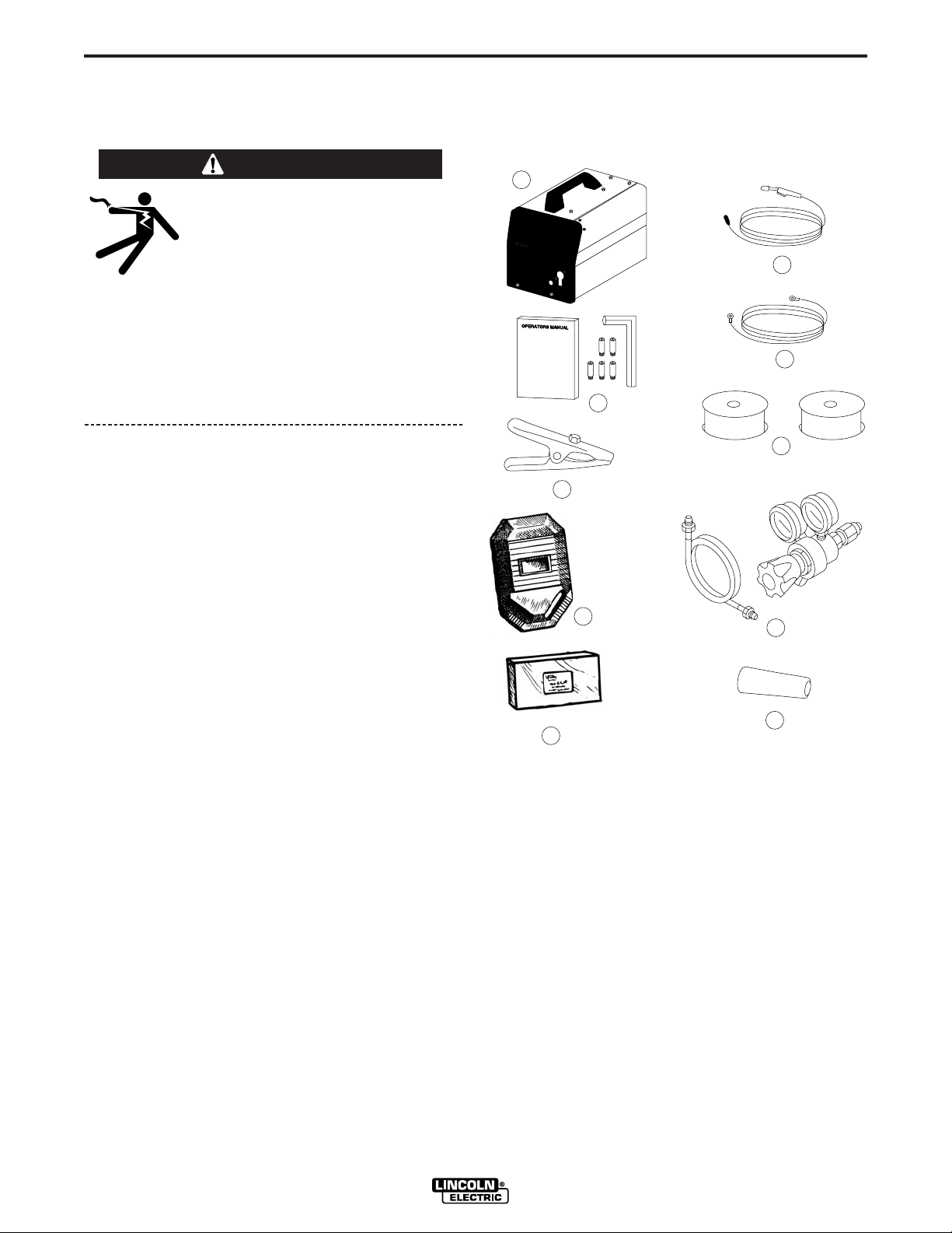
IDENTIFY AND LOCATE
COMPONENTS
If you have not already done so, unpack the Pro-MIG
140 from its carton and remove all packing material
around the Pro-MIG 140. Remove the following loose
items from the carton (see Figure A.1):
1. Pro-MIG 140
2. Gun and cable assembly
(1)
3. Literature and miscellaneous including:
a) This operating manual
b) 3 extra .023"-.025” (0.6 mm) contact tips
c) 2 extra .035” (0.9 mm) contact tips
d) Hex key wrench for removal of drive roll.
4. 10 ft (3.0 m) work cable.
5. Work clamp.
6. a) 2lb. spool of .025” (0.6 mm) Super Arc L-56
MIG wire.
b) Sample spool of Innershield .035” (0.9 mm)
NR-211-MP.
7. Welding Helmet.
8. Adjustable mixed-Gas Regulator & Hose.
9. Instructional video.
10. Nozzle.
For available options and accessories refer to the
Accessories Section of this manual.
1)
As shipped from the factory, the Pro-MIG 140 gun
liner is ready to feed .023” (0.6 mm) -.035 (0.9 mm)
wire.
ELECTRIC SHOCK can kill.
• Only qualified personnel should perform
this installation.
• Only personnel that have read and under-
stood the Pro-MIG 140 Operating Manual
should install and operate this equipment.
• Machine must be plugged into a receptacle
which is grounded per any national, local
or other applicable electrical codes.
• The Pro-MIG 140 power switch is to be in
the OFF (“O”) position when installing
work cable and gun and when connecting
power cord to input power.
WARNING
FIGURE A.1
1
2
3
4
6
7
8
5
P
ro
-M
IG
Pro-MIG
™ 1
4
0
140
9
10
A-3
INSTALLATION
Pro-MIG 140
A-3
Pro-MIG“ 140
4
5
8
3
6
7
1
2
DO NOT SWITCH
WHEN WELDING
+
-
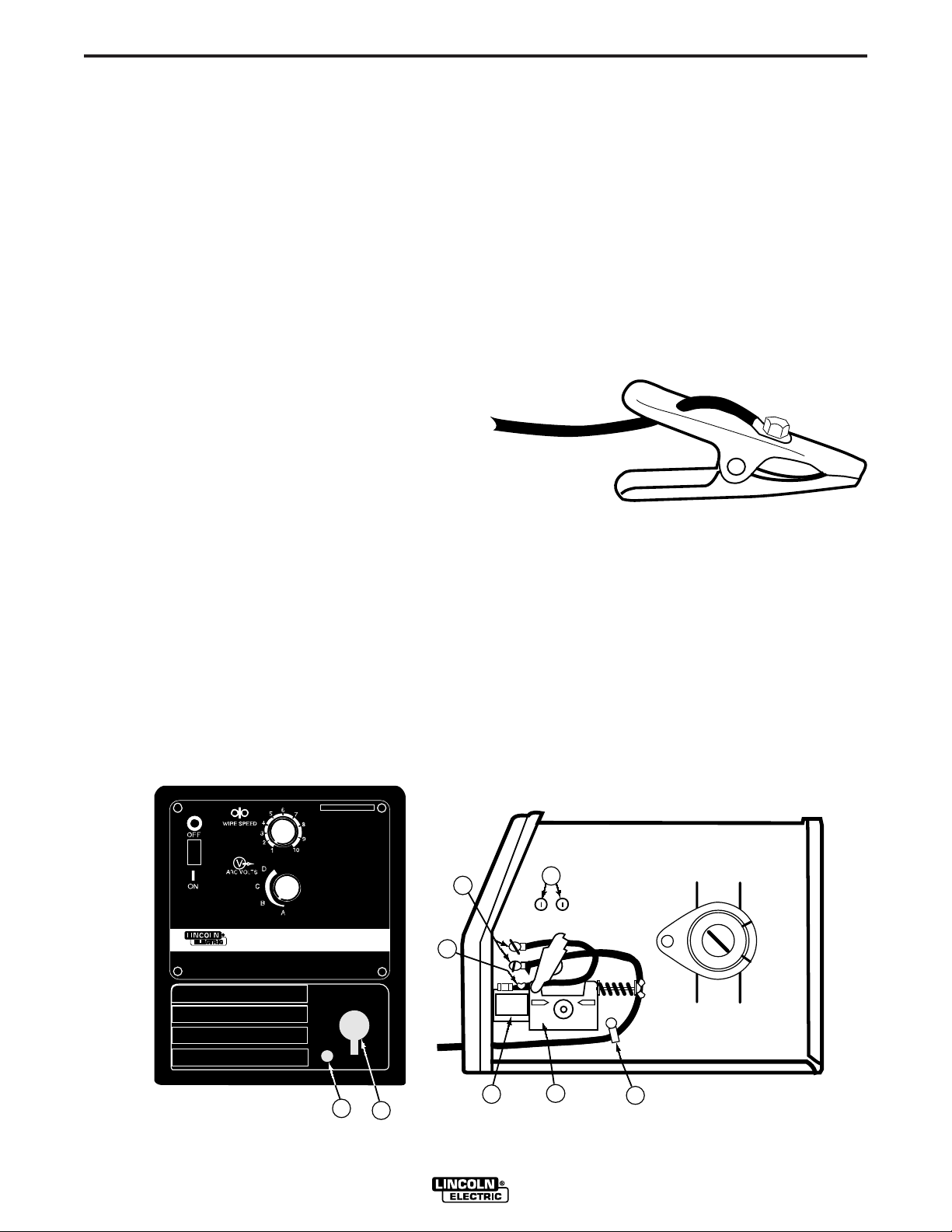
FIGURE A.2
Work Clamp Installation
Attach the work clamp per the following:
1. Unplug the machine or turn the power switch to the
“OFF” position.
2. Insert the work cable terminal lug with the larger
hole through the strain relief hole in the work clamp
as shown in Figure A-3.
3. Fasten securely with the bolt and nut provided.
FIGURE A.3
SELECT SUITABLE LOCATION
Locate the welder in a dry location where there is free
circulation of clean air into the louvers in the back and
out the front of the unit. A location that minimizes the
amount of smoke and dirt drawn into the rear louvers
reduces the chance of dirt accumulation that can block
air passages and cause overheating.
STACKING
Pro-MIG 140’s cannot be stacked.
TILTING
Each machine must be placed on a secure, level sur-
face, directly or on recommended cart. The machine
may topple over if this procedure is not followed.
OUTPUT CONNECTIONS
Refer to Figure A.2.
1. Work Cable Access Hole.
2. Gun Cable and Control Lead Access Hole.
3. Connector Block.
4. Gun Trigger Lead Connectors.
5. Positive (+) and negative (–) output terminals.
6. Wire Feed Gearbox.
7. Cable Hanger.
8. Thumbscrew.
Strain Relief Hole
Nut & Bolt
Work Clamp
Work Cable
Work Cable Installation
Refer to Figure A.2.
1. Open the wire feed section door on the right side of
the Pro-MIG 140.
2. Pass the end of the work cable that has the termi-
nal lug with the smaller hole through the Work
Cable Access Hole (1) in the case front.
3. Route the cable under and around the back of the
Wire Feed Gearbox (6).
4. For GMAW Only: Refer to Figure A.2. This is the
appropriate configuration for the GMAW (MIG)
process. To complete installation, use the provided
wing nut to connect the work cable’s terminal lug to
the negative (–) output terminal (5) located above
the Wire Feed Gearbox (6). Make sure that both
wing nuts are tight.
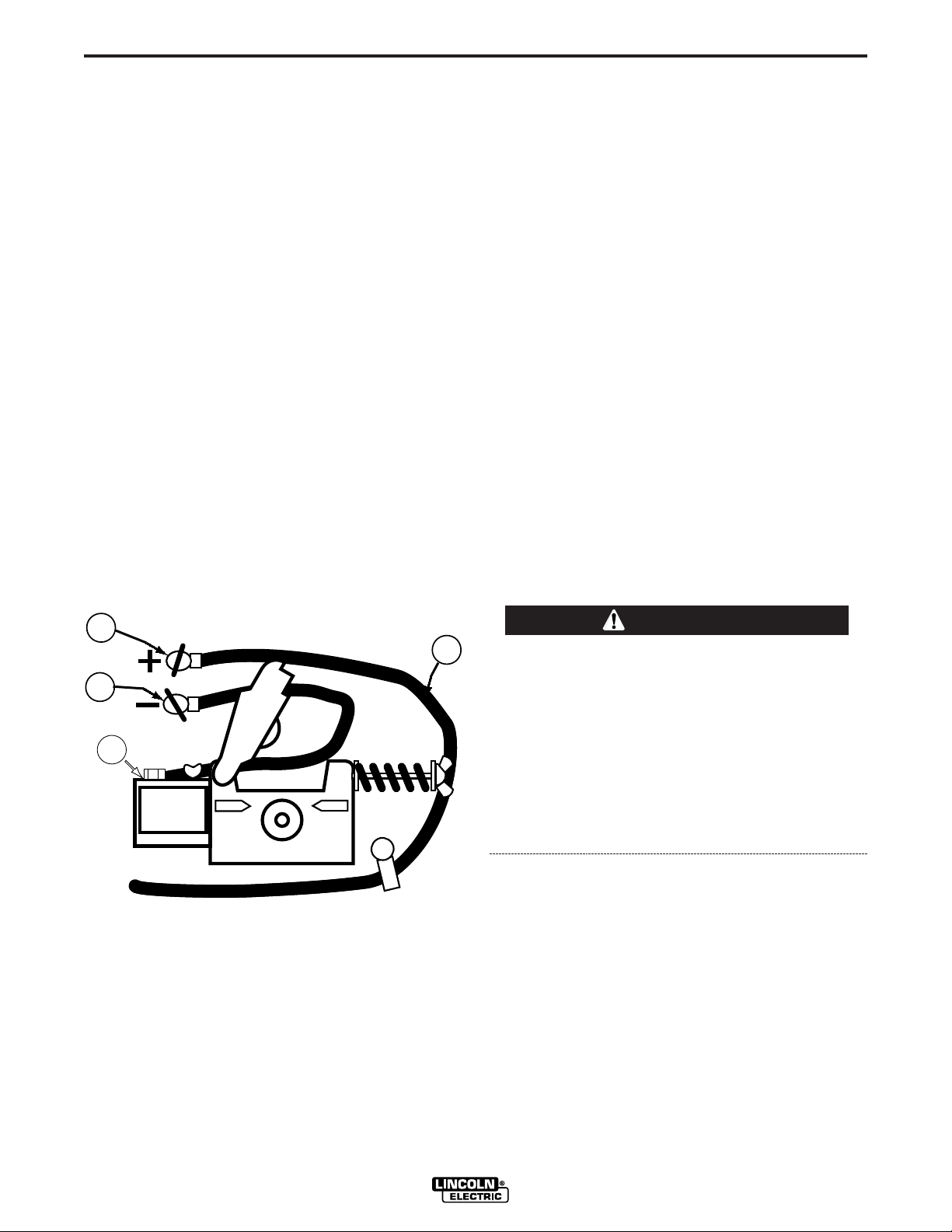
5. For Innershield Only: Refer to Figure A.4. As
delivered, the machine is connected for negative
electrode polarity. To wire for negative polarity
(required for the Innershield process), connect the
short cable attached to the connector block (1) to
the negative (–) output terminal (2) and the work
cable (3) to the positive (+) terminal (4).
A-4
INSTALLATION
Pro-MIG 140
A-4
Connecting Gun Cable to the Pro-MIG 140
1. Refer to Figure A.2. Unplug the machine or turn
power switch to the OFF “O” position.
2. Pass the insulated terminals of the gun trigger con-
trol leads, one at a time, through the Gun Cable
and Control Lead Access Slot (2) in the case front.
The leads are to be routed under the Wire Feed
Gearbox (6) and through the Cable Hanger (7) on
the inner panel.
3. Insert the connector on the gun conductor cable
through the Gun Cable Access Hole (2) in the Pro-
MIG 140 case front. Make sure the connector is all
the way into the brass connector block. Unscrew
the thumbscrew on the connector block a few turns
if gun connector will not insert fully. Rotate the con-
nector so control leads are on the underside and
tighten the Thumbscrew (8) in the connector block.
4. Connect the gun trigger control lead terminals to
the two insulated 1/4" (6.4 mm) tab terminal con-
nector bushings located below the “Gun Trigger
Connection” decal in the wire feed section (4).
Either lead can go to either connector. Form the
leads so that they are as close as possible to the
inside panel.
If the gun trigger switch being used is other than
that supplied with the Pro-MIG 140, the switch
must be a normally open, momentary switch. The
terminals of the switch must be insulated from the
welding circuit. Malfunction of the Pro-MIG 140
may result if this switch shorts to the Pro-MIG 140
welding output circuit or is common to any electri-
cal circuit other than the Pro-MIG 140 trigger cir-
cuit.
GAS CONNECTION
When using the GMAW process, a cylinder of shield-
ing gas, must be obtained. For more information about
selecting gas cylinders for use with the Pro-MIG 140
refer to the ACCESSORIES section.
2
4
3
1
FIGURE A.4
GUN INSTALLATION
As shipped from the factory, the Pro-MIG 140 is ready
to feed .035" (0.9 mm) Innershield flux-cored wire. If
.023" – .025" (0.6 mm) solid wire is to be used, use
the appropriate contact tip , diffuser and Nozzle.
CAUTION
CYLINDER may explode if dam-
aged. Keep cylinder upright and
chained to support
• Keep cylinder away from areas
where it may be damaged.
• Never lift welder with cylinder
attached.
• Never allow welding electrode to
touch cylinder.
• Keep cylinder away from welding
or other live electrical circuits.
BUILDUP OF SHIELDING GAS may
harm health or kill.
• Shut off shielding gas supply
when not in use.
• SEE AMERICAN NATIONAL
STANDARD Z-49.1, “SAFETY IN
WELDING AND CUTTING” PUB-
LISHED BY THE AMERICAN
WELDING SOCIETY.
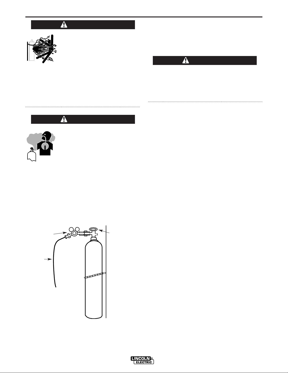
1. Chain the cylinder to a wall or other stationary sup-
port to prevent the cylinder from falling over.
Insulate the cylinder from the work circuit and earth
ground. Refer to Figure A.5.
FIGURE A.5
A-5
INSTALLATION
Pro-MIG 140
A-5
WARNING
Cylinder Valve
Gas Hose
Flow Regulator
WARNING
2. With the cylinder securely installed, remove the
cylinder cap. Stand to one side away from the out-
let and open the cylinder valve very slightly for an
instant. This blows away any dust or dirt which may
have accumulated in the valve outlet.
BE SURE TO KEEP YOUR FACE AWAY FROM
THE VALVE OUTLET WHEN “CRACKING” THE
VALVE. Never stand directly in front of or behind
the flow regulator when opening the cylinder
valve. Always stand to one side.
3. Attach the flow regulator to the cylinder valve and
tighten the union nut securely with a wrench.
NOTE: If connecting to 100% CO
2
cylinder, make
certain the plastic washer is seated in the fitting
that attaches to the CO
2
cylinder.
4. Refer to Figure A.6. Attach one end of inlet gas
hose to the outlet fitting of the flow regulator and
tighten the union nut securely with a wrench.
Connect the other end to the Pro-MIG 140 Gas
Solenoid Inlet Fitting (5/8-18 female threads — for
CGA — 032 fitting). Make certain the gas hose is
not kinked or twisted.
WARNING
A-6
INSTALLATION
Pro-MIG 140
A-6
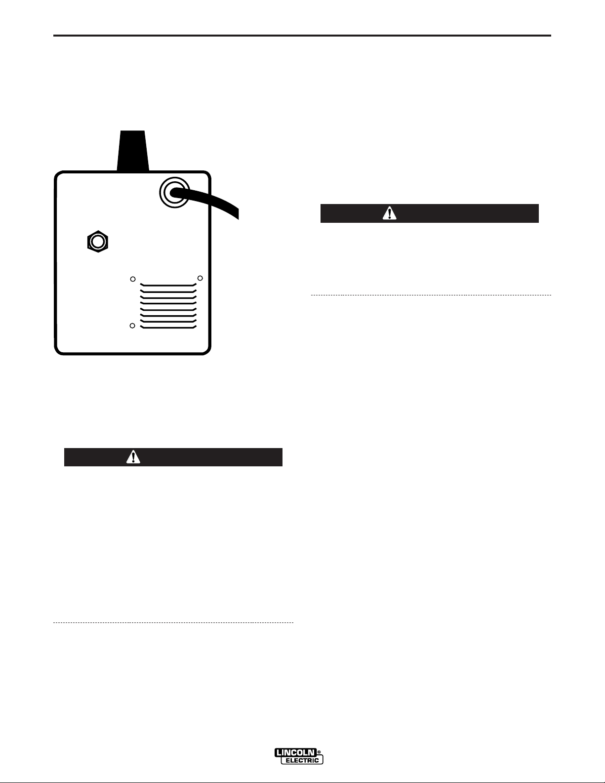
INPUT CONNECTIONS
Refer to Figure A.6.
The Pro-MIG 140 has a power input cable located on
the rear of the machine.
FIGURE A.6
CODE REQUIREMENTS FOR INPUT
CONNECTIONS
This welding machine must be connected to a
power source in accordance with applicable elec-
trical codes.
The National Electrical Code provides standards
for amperage handling capability of supply con-
ductors based on duty cycle of the welding
source.
If there is any question about the installation
meeting applicable electrical code requirements,
consult a qualified electrician.
Requirements For Rated Output
A power cord with a 15 amp, 125 volt, three prong
plug (NEMA Type 5-15P) is factory installed on the
Pro-MIG 140. Connect this plug to a mating grounded
receptacle which is connected to a 20 amp branch cir-
cuit with a nominal voltage rating of 115 to 125 volts,
60 Hertz, AC only.
The rated output with this installation is 90 amps,19
Volts, 20% duty cycle (2 minutes of every 10 minutes
used for welding).
Do not connect the Pro-MIG 140 to an input power
supply with a rated voltage that is greater than 125
volts.
Do not remove the power cord ground prong.
POWER INPUT
CABLE
GAS SOLENOID
INLET FITTING
WARNING
CAUTION
B-1
OPERATION
B-1
Pro-MIG 140
Read entire operation section before
operating the Pro-MIG 140.
ELECTRIC SHOCK can kill.
• Do not touch electrically live
parts or electrode with skin or
wet clothing. Insulate yourself
from work and ground.
• Always wear dry insulating
gloves.
FUMES AND GASES can be
dangerous.
• Keep your head out of fumes.
• Use ventilation or exhaust to
remove fumes from breathing
zone.
WELDING SPARKS can
cause fire or explosion.
• Keep flammable material away.
• Do not weld on closed contain-
ers.
ARC RAYS can burn eyes
and skin.
• Wear eye, ear and body protec-
tion.
Observe all safety information throughout
this manual.
WARNING
GENERAL DESCRIPTION
The Pro-MIG 140 is a complete semiautomatic con-
stant-voltage DC wire feeder / power source arc
welder. It has been designed for workshop, hobby,
automotive and light maintenance. Included is a tap-
switch controlled, single phase constant voltage trans-
former / rectifier power source and a wire feeder weld-
ing gun for feeding .023 - .025” (0.6 mm) through
.030” (0.8 mm) solid steel electrode. An optional kit is
available for feeding .035” (0.9 mm) Innershield
®
NR-
211-MP flux-cored wire.
The Pro-MIG 140 is ideally suited for individuals hav-
ing access to 120 volt AC input power, and wanting
the ease of use, quality and dependability of both gas
metal arc welding or GMAW (also known as MIG
welding) and the Innershield electrode process (self
shielded flux cored or FCAW). The Pro-MIG 140 is a
rugged and reliable machine that has been designed
for dependable service and long life.
RECOMMENDED PROCESSES
The Pro-MIG 140 can be used for welding mild steel
using the Gas Metal Arc Welding (GMAW or MIG,
Metal Inert Gas) single pass process, which requires a
supply of shielding gas, or the flux-cored arc welding
(FCAW) process using Innershield
®
electrode wire.
The Pro-MIG 140 is configured for use with the FCAW
process as delivered from the factory.
OPERATIONAL CONTROLS
The Pro-MIG 140 has the following controls as stan-
dard: Control Power ON/OFF Switch, Voltage Control,
Wire Speed Control, Trigger Switch, and a Circuit
Breaker.
DESIGN FEATURES
● Operates on 120 volt input
● “Cold electrode” until gun trigger is pressed for an
added measure of safety.
● Overload protection — incorporates both a thermo-
stat and a circuit breaker.
● Quality wire drive with electronic overload protec-
tion.
● “Quick Release” idle roll pressure arm is easily
adjusted.
● Reversible, dual groove drive roll. Drive roll will
feed .023 – .025” (0.6 mm) and .030" - .035" (0.8 -
0.9 mm) diameter wire.
B-2
OPERATION
B-2
Refer to Figure B.1b.
4. Circuit Breaker – Protects machine from damage if
maximum output is exceeded. Button will extend
out when tripped (Manual reset).
5. Gun Trigger - Activates welding output, wire feed,
and gas solenoid operation. Releasing the trigger
deactivates welding and simultaneously activates
the “burnback” function so that the welding wire
does not stick in the weld puddle.
FIGURE B.1a
FIGURE B.1b
● No external shielding gas is required when used
with Lincoln Innershield .035” (0.9 mm) NR
®
-211-
MP electrode.
● Accommodates both 4” (100 mm) diameter and 8”
(200 mm) diameter spools of wire.
WELDING CAPABILITY
The Pro-MIG 140 is rated at 90 amps, 19 volts, at
20% duty cycle on a ten minute basis. It is capable of
higher output currents at lower duty cycles.
LIMITATIONS
Arc Gouging cannot be performed with the Pro-MIG
140. The Pro-MIG 140 is not recommended for pipe
thawing or TIG welding.
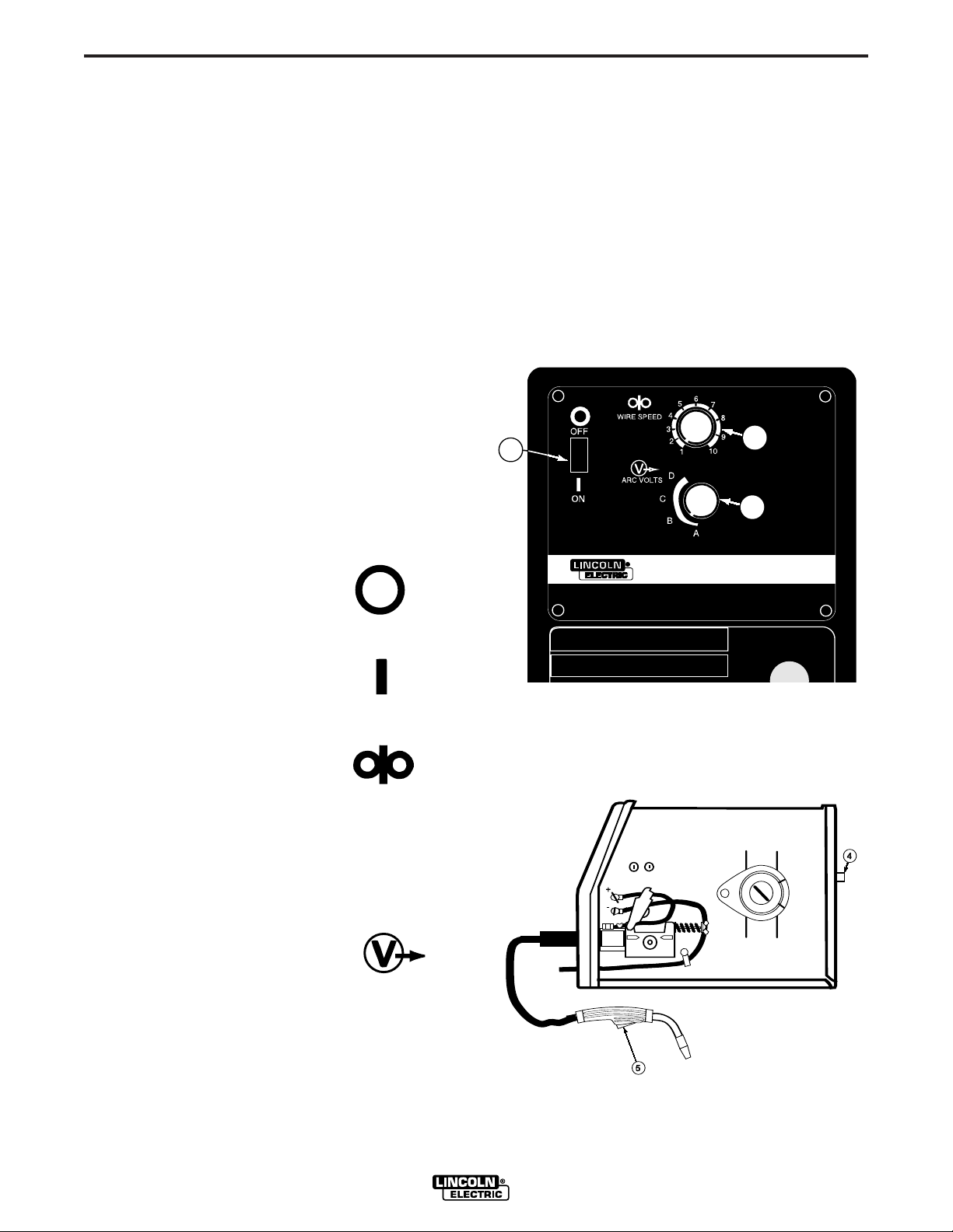
CONTROLS AND SETTINGS
Refer to Figure B.1a.
1. Control Power ON/OFF Switch
— When the power is on the
fan motor will run and air will be
exhausted out the louvers in the
front of the machine. The weld-
ing output and wire feeder
remain off until the gun trigger
is pressed.
2. Wire Speed Control —
Controls the wire feed speed
from 50 – 300 in /min. (1.3 –
7.6 m/min.). The control can
be preset on the dial to the
setting specified on the Pro-
MIG 140 Application Chart
located on the inside of the
wire feed section door.
3. Voltage Control — A 4-posi-
tion tap selector switch gives
full range adjustment of
power source output voltage.
Do not switch while welding
as damage to switch may
occur.
Pro-MIG 140
OFF
ON
ARC VOLTS
WIRE SPEED
Pro-MIG™ 140
DO NOT SWITCH
WHEN WELDING
3
2
1
B-3
OPERATION
B-3
WELDING OPERATIONS
SEQUENCE OF OPERATION
Wire Loading
Refer to Figures B.2 and B.3.
The machine power switch should be turned to the
OFF (“O”) position before working inside the wire feed
enclosure.
The welder is shipped from the factory ready to feed
8" (200 mm) diameter spools with 2.2" (56 mm) maxi-
mum width. These spools fit on a 2" (51 mm) diameter
spindle that has a built in, adjustable friction brake to
prevent overrun of the spool and excess slack in the
wire.
Note:When loading and removing the 8” Spools
make
sure that the wing nut (inside the wire spool spindle
hub) is turned 90° from the wire spool spindle locking
tab. If the wing nut is positioned in line with the locking
tab, the tab cannot be depressed to load or unload the
wire spool.
FIGURE B.2
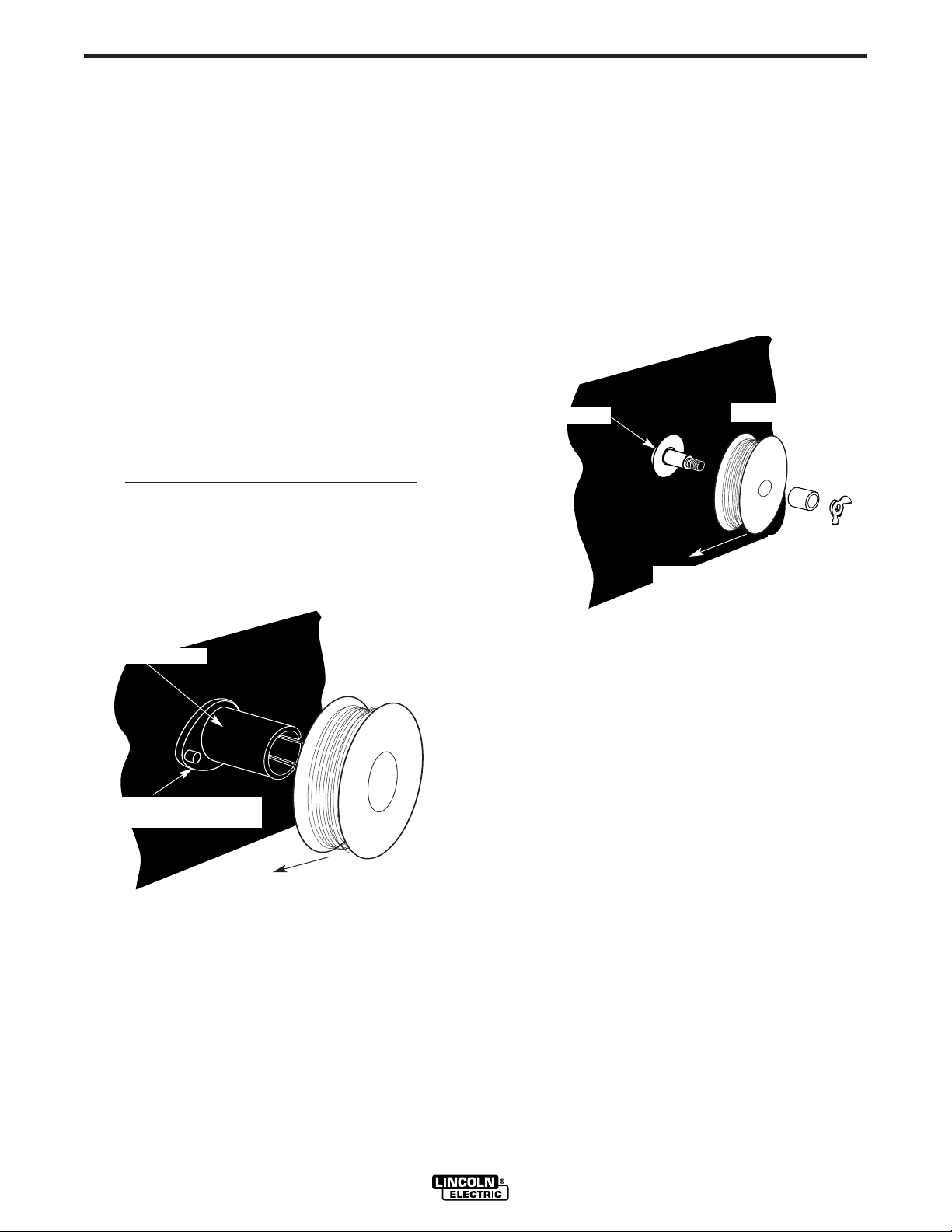
Load an 8” (200 mm) diameter spool on the wire spool
spindle shown in Figure B.2.
To use 4” (100 mm) diameter spools, the 2” (50 mm)
diameter spindle must be removed (See Figure B.3).
Remove the wing nut and spacer at the end of the
shaft and remove the outside plastic wire spool spin-
dle. The spindle can be stored in the wire feed com-
partment. A 4” (100 mm) diameter spool is mounted
directly on the 5/8” (16 mm) diameter shaft and held in
place with the previously removed hardware. Also
make certain the start end of the wire, which may pro-
trude through the side of the spool does not contact
any metallic case parts.
FIGURE B.3
Pro-MIG 140
Wire Spindle Shaft
To Wire Drive
4" Wire Spool
Wing Nut
and Spacer
Wire Spool must be pushed all the way on the spindle so that the
spindles tab will hold it in place. The Wire Spool will rotate clock-
wise when wire is dereeled.
Be sure that this stud engages
the hole in the wire spool.
To Wire Drive
Wire Spool Spindle
8” Wire Spool
B-4
OPERATION
B-4
Friction Brake Adjustment
With wire spool installed on the spindle shaft and the
wing nut loose, turn the spool by hand while slowly
tightening the wing nut until a light drag is felt. Tighten
the wing nut an additional 1/4 turn.
Note: When properly adjusted, the brake should pro-
vide only enough drag to prevent overrun of the spool
and excess slack in the wire. Too much drag may
result in wire feeding problems, and may cause pre-
mature wear of wire drive system components.
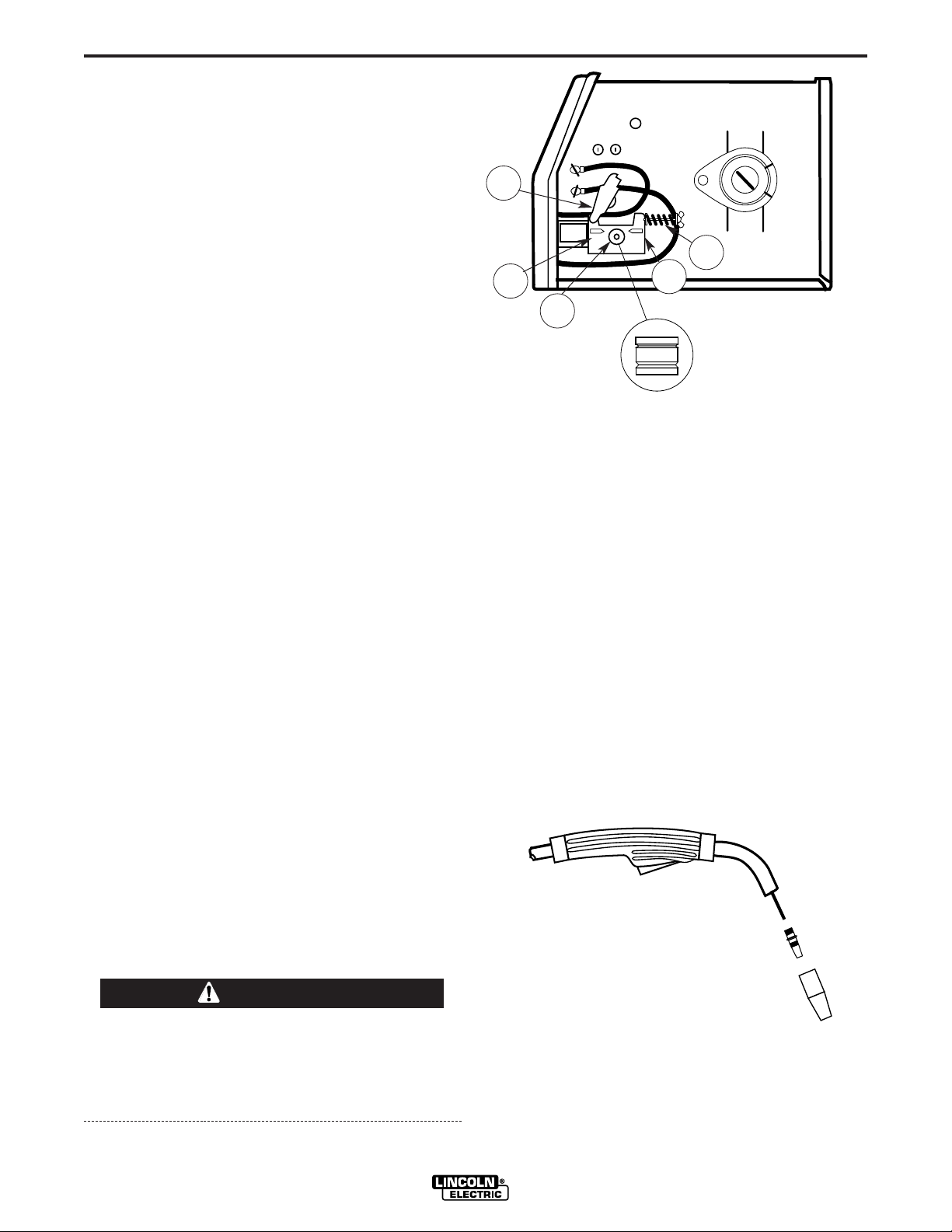
Wire Threading
Refer to Figure B.4
1. Release the Spring Loaded Pressure Arm (1)
rotate the Idle Roll Arm (2) away from. the Wire
Feed Drive Roll (3). Ensure that the groove size in
the feeding position on the drive roll matches the
wire size being used.
2. Carefully detach the end of the wire from the
spool. To prevent the spool from unwinding,
maintain tension on the wire until after step 5.
3. Cut the bent portion of wire off and straighten the
first 4” (100 mm).
4. Thread the wire through the In-going guide tube
(4), over the drive roll (3), and into the out-going
guide tube (5).
5. Close the idle roll arm (2) and latch the spring
loaded pressure arm (1) in place. Rotate the spool
counterclockwise if required in order to take up
extra slack in the wire.
6. The idle roll pressure adjustment wing nut is facto-
ry set to approximately five full turns from where
the wing nut first engages the threads of the pres-
sure arm (1). If feeding problems occur because
the wire is flattened excessively, turn the pressure
adjustment counter-clockwise to reduce distortion
of the wire. Slightly less pressure may be required
when using 0.023 – 0.025" (0,6 mm) wire. If the
drive roll slips while feeding wire, the pressure
should be increased until the wire feeds properly.
When inching the welding wire, the drive rolls, the
gun connector block and the gun contact tip are
electrically energized relative to work and ground
and remain energized for several seconds after
the gun trigger is released.
FIGURE B.4
7. Refer to Figure B.5. Remove gas nozzle and con-
tact tip from end of gun.
8. Turn the Pro-MIG 140 ON (“I”).
9. Straighten the gun cable assembly.
10. Depress the gun trigger switch and feed welding
wire through the gun and cable. (Point gun away
from yourself and others while feeding wire.)
Release gun trigger after wire appears at end of
gun.
11. Turn the Pro-MIG 140 OFF (“O”).
12. Replace contact tip and gas nozzle.
13. Refer to Figure B-6. Cut the wire off 3/8” – 1/2” (10
– 13 mm) from the end of the tip. The Pro-MIG
140 is now ready to weld.
FIGURE B.5
Pro-MIG 140
WARNING
The Wire Drive Feed Roll can
accommodate two wire sizes
by flipping the wire drive feed
roll over.
1
2
3
4
5
Gun Handle
Gas Diffuser/
Contact Tip
Gas Nozzle
B-5
OPERATION
B-5
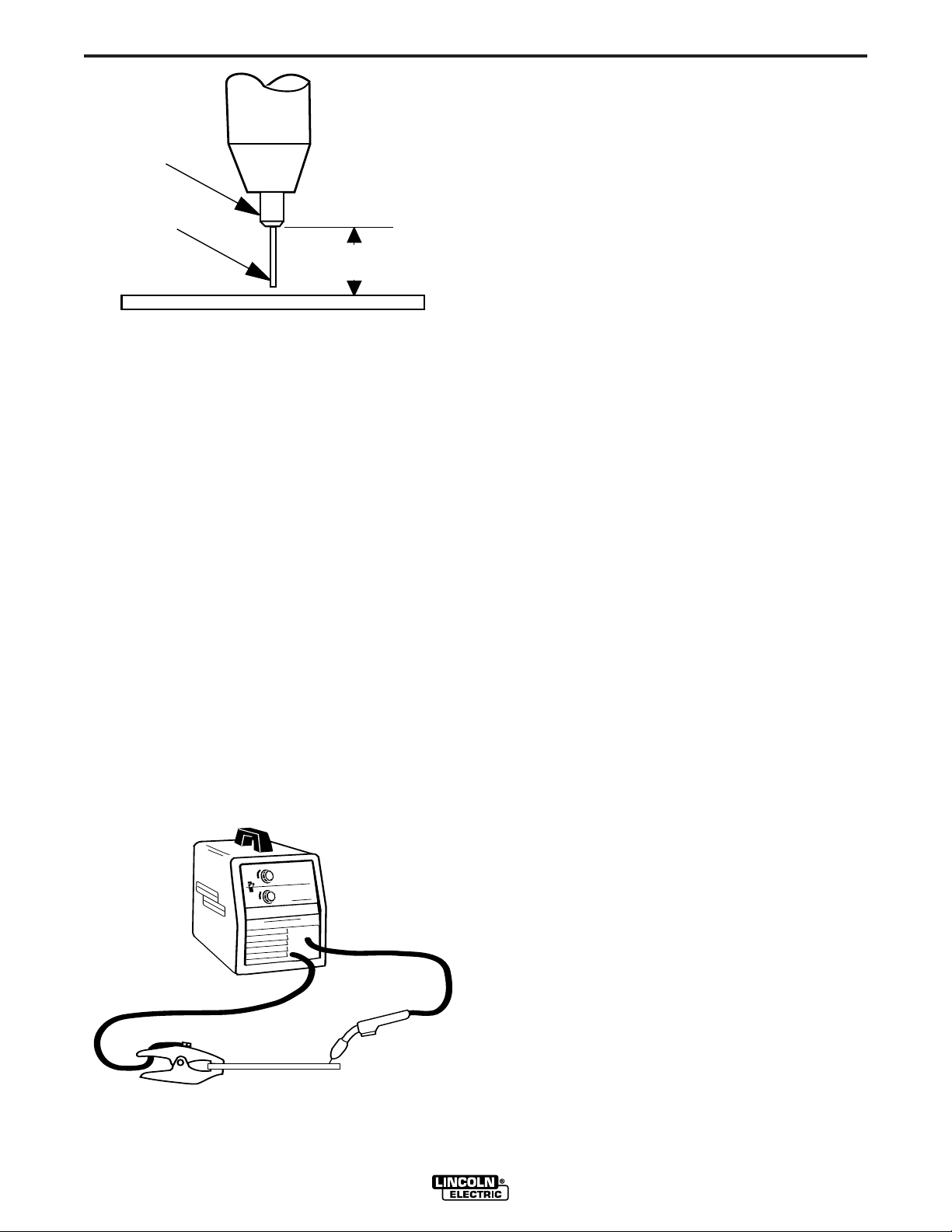
FIGURE B.6
Making A Weld
1. See “Process Guidelines” in this section for selec-
tion of welding wire and shielding gas and for
range of metal thicknesses that can be welded.
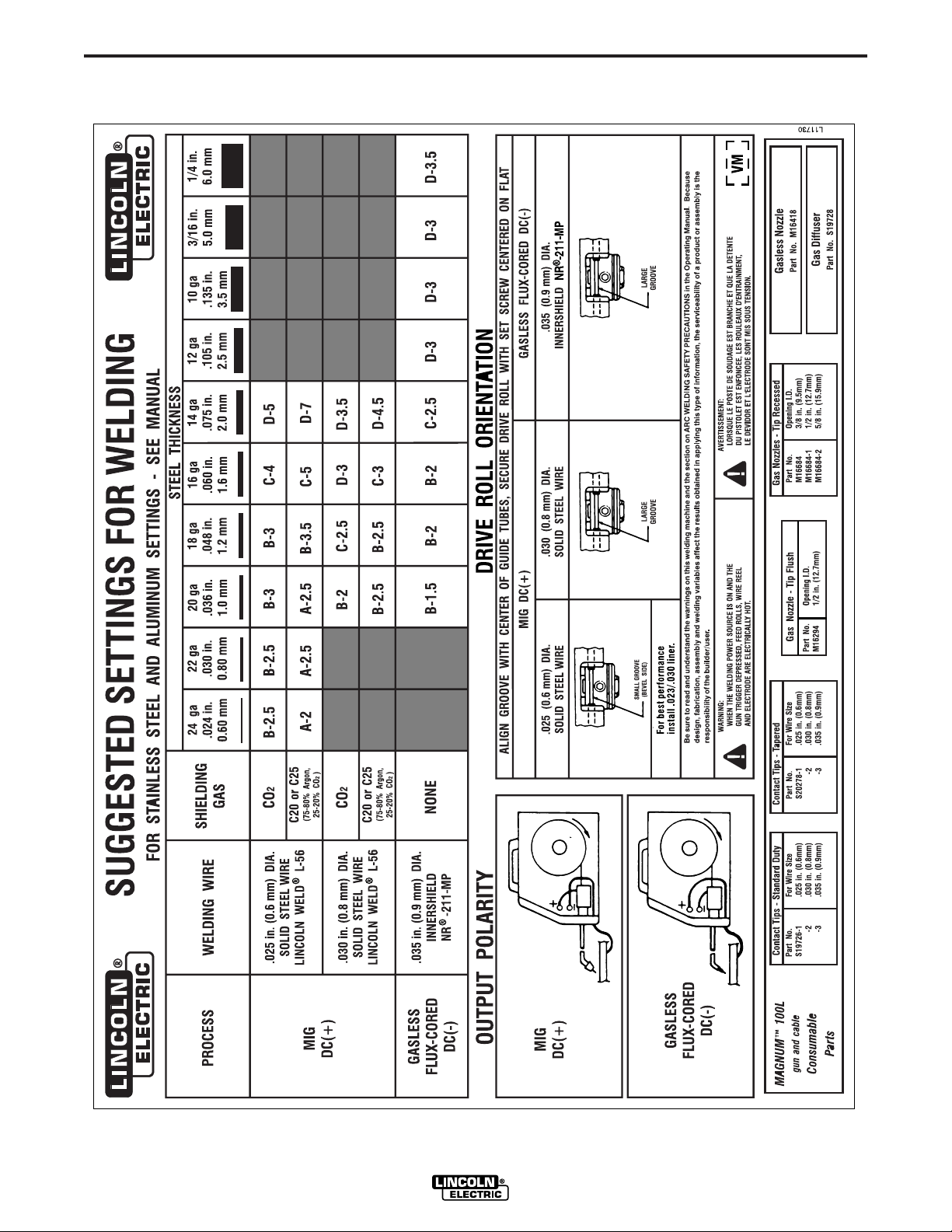
2. See the Application chart on the inside of the wire
feed compartment door for information on setting
the Pro-MIG 140 controls. Refer to Table B.1 for
aluminum and stainless wire.
3. Set the Voltage (“V”) and Wire Speed (“olo’”) con-
trols to the settings suggested for the welding wire
and base metal thickness being used, refer to
Applications chart on the inside of the wire drive
compartment door.
4. Check that the polarity is correct for the welding
wire being used and that the gas supply, if
required, is turned on.
5. When using Innershield electrode, remove the gas
nozzle and install the gasless nozzle. This will
improve visibility of the arc and protect the gas dif-
fuser from weld spatter. Refer to the MAINTE-
NANCE section for details on nozzle replacement.
FIGURE B.7
6. Refer to Figure B.7. Connect work clamp to metal
to be welded. Work clamp must make good elec-
trical contact to the workpiece. The workpiece
must also be grounded as stated in “Arc Welding
Safety Precautions” in the beginning of this manu-
al.
7. Position gun over joint. End of wire may be lightly
touching the work.
8. Place hand shield in front of face, close gun trig-
ger, and begin welding. Hold the gun so the con-
tact tip to work distance is about 3/8 inch (10 mm).
9. To stop welding, release the gun trigger and then
pull the gun away from the work after the arc goes
out.
10. When no more welding is to be done, close valve
on gas cylinder (if used), momentarily operate gun
trigger to release gas pressure, and turn off the
Pro-MIG 140.
Cleaning Tip And Nozzle
Clean the contact tip and nozzle to avoid arc bridging
between the nozzle and contact tip which can result in
a shorted nozzle, poor welds and an overheated gun.
Hint: Anti-stick spray or gel, available from a welding
supply distributor, may reduce buildup and aid in spat-
ter removal.
PROCESS GUIDELINES
The Pro-MIG 140 can be used for welding mild steel
using the GMAW, single pass process which requires
a supply of shielding gas or it can be used for the self-
shielded, Innershield
®
process (FCAW).
The recommended gases and electrodes for GMAW
are welding grade CO
2
gas or an argon-CO
2
blended
gas (75 to 80% argon and 25 to 20% CO
2
) and .025"
(0.6 mm) diameter Lincoln Super Arc L-56 mild-steel
welding wire, supplied on 12-1/2 lb (5.7 kg) spools.
The recommended electrode for the self-shielded
process is .035” (0.9 mm) diameter Lincoln
Innershield
®
NR-211-MP. This electrode can be used
for all position welding of 20 gauge (1.0 mm) through
5/16" (8 mm) steel. Thickness of 1/4" (6 mm) and
5/16" (8 mm) require multiple passes. This wire can
also be used for the welding of galvanized coated
sheet metal.
Pro-MIG 140
Contact Tip
Wire Electrode
WORKPIECE
GUN CABLE
ARC
WORK CLAMP
Pro-MIG
™ 140
3/8"– 1/2"(10-13mm) Contact
Tip to Work Distance(CTWD)

B-6
OPERATION
B-6
The Pro-MIG 140 is suitable for .035" aluminum wire
and .030" stainless wire. Refer to Table B.1 for recom-
mended procedure settings.
TABLE B.1
NOTE:
NR - Not Recommended
CHANGING MACHINE OVER TO
FEED OTHER WIRE SIZES
The Pro-MIG 140 is shipped from the factory ready to
feed .035” (0.9 mm) diameter wire. To operate the
Pro-MIG 140 with other sizes of wire, it is necessary
to change the appropriate contact tip, diffuser, nozzle
and change the drive roll over to other sizes. Refer to
Changing the Contact Tip and Changing the Drive
Roll, in the MAINTENANCE section, for specific infor-
mation on these procedures.
WELDING WITH GMAW (MIG)
Shielding Gas
When using the GMAW process, the correct drive roll
and electrode polarity must be used. See Work Cable
Installation in INSTALLATION section for changing
the polarity.
When using the GMAW process, obtain and install a
gas regulator and hose kit. If using CO
2
a CO
2
adapter is required, sold separately.
1. For CO
2
, open the cylinder very slowly. For argon-
mixed gas, open cylinder valve slowly a fraction of
a turn. When the cylinder pressure gauge pointer
stops moving, open the valve fully.
2. If using a regulator with an adjustable flow meter,
close the gun trigger and adjust the flow to give 15
– 20 cubic ft per hour (CFH) (7 – 10 I/min.) [use 20
– 25 CFH (10 – 12 I/min.) when welding out of
position or in a drafty location for CO
2
]. For argon
mixed gas, trigger to release gas pressure, and
adjust the flow to give 25 – 30 CFH (12 – 14
I/min.).
3. Keep the cylinder valve closed, except when using
the Pro-MIG 140. When finished welding:
a) Close the cylinder valve to stop gas flow.
b) Depress the gun trigger briefly to release the
pressure in the gas hose.
c) Turn off the Pro-MIG 140.
WELDING WITH FCAW (Innershield)
When using the FCAW process, the correct drive roll
and electrode polarity must be used. See Work Cable
Installation in INSTALLATION section for changing
the polarity.
OVERLOAD PROTECTION
Output Overload
The Pro-MIG 140 is equipped with a circuit breaker
and a thermostat which protects the machine from
damage if maximum output is exceeded. The circuit
breaker button will extend out when tripped. The cir-
cuit breaker must be manually reset.
Thermal Protection
The Pro-MIG 140 has a rated output duty cycle of
20%. If the duty cycle is exceeded, a thermal protector
will shut off the output until the machine cools to a
reasonable operating temperature. This is an auto-
matic function of the Pro-MIG 140 and does not
require user intervention. The fan continues to run
during cooling.
Electronic Wire Drive Motor Protection
The Pro-MIG 140 has built-in protection for wire drive
motor overload.
Pro-MIG 140
Shielding
Voltage/Wire Speed
Process Welding Wire Gas 22 ga 16 ga 12 ga 1/8” 3/16” 1/4”
.035 Dia(0.9mm 100% Argon A-4.5 C-8.5 D-10 NR NR NR
4043 Aluminum
Wire
MIG DC+
18 ga 16 ga 14 ga 12 ga 10ga
.030 Dia 98% Argon/ B-6 C-6.5 D-7.5 NR NR
308L Stainless 2% Oxygen
Steel Wire
B-7
APPLICATION CHART
B-7
Pro-MIG 140

C-1
ACCESSORIES
C-1
OPTIONAL ACCESSORIES
1. K664-2 Aluminum Feeding Kit — This kit is rec-
ommended for welding with .035 Aluminum wire.
This kit may also be used for feeding .035 stainless
wire. Included with this kit are a drive roll, liner and
contact tip. It is important when changing
between welding with steel wire and aluminum
to exchange these components due to the
lubricant applied to steel wire. Failure to do so
may result in contaminated welds when weld-
ing aluminum.
2. K520 Utility Cart — Designed to transport the
Lincoln family of small welders. Has provisions for
mounting a single gas cylinder. Has front casters
and large rear wheels. Handle height is easily
adjustable. Bottom tray provided for tools and
accessories. Easy assembly required; takes less
than 15 minutes.
3. K586-1 Deluxe Adjustable Gas Regulator &
Hose Kit
Accommodates CO
2
or mixed Gas Cylinders.
Pro-MIG 140
 Loading...