


Return to Master TOC |
View Safety Info |
Return to Master TOC |
View Safety Info |
Return to Master TOC |
View Safety Info |
Return to Master TOC |
View Safety Info |
RETURN TO MAIN INDEX
SVM104-A
March, 1999
PRO-CUT ™ 60 (Single Phase)
For use with machines having Code Numbers: 9819, 10096, 10112
10118, 10217, 10218 10393, 10394
Safety Depends on You
Lincoln arc welding and cutting equipment is designed and built with safety in mind. However, your overall safety can be increased by proper installation ... and thoughtful operation on your part. DO NOT
INSTALL, OPERATE OR REPAIR THIS EQUIPMENT WITHOUT READING THIS MANUAL AND THE SAFETY PRECAUTIONS CONTAINED THROUGHOUT.
And, most importantly, think before you act and be careful.
ON
OFF
o
1
SERVICE MANUAL
|
|
|
|
|
|
|
|
|
|
|
|
|
|
|
|
|
|
|
|
|
|
|
|
|
|
|
|
|
|
|
|
|
|
|
|
|
|
|
|
|
|
|
|
|
|
|
|
|
|
|
|
|
|
|
|
|
|
|
|
|
|
|
|
|
|
|
|
|
|
|
|
|
|
|
|
|
|
World's Leader in Welding and Cutting Products |
|
|
Premier Manufacturer of Industrial Motors |
|
|||||
|
|
|
|
|||||||
|
|
• Sales and Service through Subsidiaries and Distributors Worldwide • |
|
|||||||
|
Cleveland, Ohio 44117-1199 U.S.A. TEL: 216.481.8100 |
FAX: 216.486.1751 WEB SITE: www.lincolnelectric.com |
|
|||||||
Return to Master TOC
Return to Master TOC
Return to Master TOC
Return to Master TOC
SAFETY |
i |
|||
|
|
|
|
|
WARNING |
|
CUTTING can be hazardous. |
||
PROTECT YOURSELF AND OTHERS FROM POSSIBLE SERIOUS INJURY OR DEATH. KEEP CHILDREN AWAY. PACEMAKER WEARERS SHOULD CONSULT WITH THEIR DOCTOR BEFORE OPERATING.
Read and understand the following safety highlights. For additional safety information, it is strongly recommended that you purchase a copy of “Safety in Welding & Cutting - ANSI Standard Z49.1” from the American Welding Society, P.O. Box 351040, Miami, Florida 33135 or CSA Standard W117.2-1974. A Free copy of “Arc Welding Safety” booklet E205 is available from the Lincoln Electric Company, 22801 St. Clair Avenue, Cleveland, Ohio 44117-1199.
BE SURE THAT ALL INSTALLATION, OPERATION, MAINTENANCE AND REPAIR PROCEDURES ARE PERFORMED ONLY BY QUALIFIED INDIVIDUALS.
ELECTRIC SHOCK
can kill.
1.a. The electrode and work (or ground) circuits are electrically “hot” when the welder or cutter is on. Do not touch these “hot” parts with your bare skin or wet clothing. Wear dry, hole-free gloves to insulate hands.
1.b. Insulate yourself from work and ground using dry insulation. Make certain the insulation is large enough to cover your full area of physical contact with work and ground.
In addition to the normal safety precautions, if welding or cutting must be performed under electrically hazardous conditions (in damp locations or while wearing wet clothing; on metal structures such as floors, gratings or scaffolds; when in cramped positions such as sitting, kneeling or lying, if there is a high risk of unavoidable or accidental contact with the workpiece or ground) use the following equipment:
•Semiautomatic DC Constant Voltage (Wire) Welder.
•DC Manual (Stick) Welder.
•AC Welder with Reduced Voltage Control.
1.c. In semiautomatic or automatic wire welding, the electrode, electrode reel, welding head, nozzle or semiautomatic welding gun are also electrically “hot”.
1.d. Always be sure the work cable makes a good electrical connection with the metal being welded. The connection should be as close as possible to the area being welded.
1.e. Ground the work or metal to be welded to a good electrical (earth) ground.
1.f. Maintain the electrode holder, work clamp, welding or cutting cable and welding or cutting machine in good, safe operating condition. Replace damaged insulation.
1.g. Never dip the electrode in water for cooling.
1.h. Never simultaneously touch electrically “hot” parts of electrode holders connected to two welders because voltage between the two can be the total of the open circuit voltage of both welders.
1.i. When working above floor level, use a safety belt to protect yourself from a fall should you get a shock.
1.j. Also see Items 4.c. and 6.
ARC RAYS can burn.
2.a. Use a shield with the proper filter and cover plates to protect your eyes from sparks and the rays of the arc when welding or cutting or observing open arc welding or cutting. Headshield and filter lens should conform to ANSI Z87. I standards.
2.b. Use suitable clothing made from durable flame-resistant material to protect your skin and that of your helpers from the arc rays.
2.c. Protect other nearby personnel with suitable, non-flammable screening and/or warn them not to watch the arc nor expose themselves to the arc rays or to hot spatter or metal.
FUMES AND GASES can be dangerous.
3.a. Welding or cutting may produce fumes and
gases hazardous to health. Avoid breathing these fumes and gases.When welding, or cutting keep your head out of the fume. Use enough ventilation and/or exhaust at the arc to keep fumes and gases away from the breathing zone. When welding or cut-
ting with electrodes which require special ventilation such as stainless or hard facing (see instructions on container or MSDS) or on lead or cadmium plated steel and other metals or coatings which produce highly toxic fumes, keep exposure as low as possible and below Threshold Limit Values (TLV) using local exhaust or mechanical ventilation. In confined spaces or in some circumstances, outdoors, a respirator may be required. Additional precautions are also required when welding on galvanized steel.
3.b. Do not weld or cut in locations near chlorinated hydrocarbon vapors coming from degreasing, cleaning or spraying operations. The heat and rays of the arc can react with solvent vapors to form phosgene, a highly toxic gas, and other irritating products.
3.c. Shielding gases used for arc welding or cutting can displace air and cause injury or death. Always use enough ventilation, especially in confined areas, to insure breathing air is safe.
3.d. Read and understand the manufacturer’s instructions for this equipment and the consumables to be used, including the material safety data sheet (MSDS) and follow your employer’s safety practices. MSDS forms are available from your welding distributor or from the manufacturer.
3.e. Also see item 7b.
PRO-CUT 60
Return to Master TOC
Return to Master TOC
Return to Master TOC
Return to Master TOC
SAFETY |
ii |
WELDING OR CUTTING


 SPARKS can cause fire or explosion.
4.a. Remove fire hazards from the welding or cutting area. If this is not possible, cover them to prevent the welding or cutting sparks from start-
ing a fire. Remember that welding or cutting sparks and hot materials from welding or cutting can easily go through small cracks and openings to adjacent areas. Avoid welding or cutting near hydraulic lines. Have a fire extinguisher readily available.
4.b. Where compressed gases are to be used at the job site, special precautions should be used to prevent hazardous situations. Refer to “Safety in Welding and Cutting” (ANSI Standard Z49.1) and the operating information for the equipment being used.
4.c. When not welding or cutting, make certain no part of the electrode circuit is touching the work or ground. Accidental contact can cause overheating and create a fire hazard.
4.d. Do not heat, cut or weld tanks, drums or containers until the proper steps have been taken to insure that such procedures will not cause flammable or toxic vapors from substances inside. They can cause an explosion even though they have been “cleaned”. For information, purchase “Recommended
Safe Practices for the Preparation for Welding and Cutting of Containers and Piping That Have Held Hazardous Substances”, AWS F4.1 from the American Welding Society (see address above).
4.e. Vent hollow castings or containers before heating, cutting or welding. They may explode.
4.f. Sparks and spatter are thrown from the welding and cutting arc. Wear oil free protective garments such as leather gloves, heavy shirt, cuffless trousers, high shoes and a cap over your hair. Wear ear plugs when welding or cutting out of position or in confined places. Always wear safety glasses with side shields when in a welding or cutting area.
4.g. Connect the work cable to the work as close to the welding or cutting area as practical. Work cables connected to the building framework or other locations away from the welding area increase the possibility of the welding or cutting current passing through lifting chains, crane cables or other alternate circuits. This can create fire hazards or overheat lifting chains or cables until they fail.
CYLINDER may explode


 if damaged.
5.a. Use only compressed gas cylinders
containing the correct shielding gas for the process used and properly operating regulators designed for the gas and
pressure used. All hoses, fittings, etc. should be suitable for the application and maintained in good condition.
5.b. Always keep cylinders in an upright position securely chained to an undercarriage or fixed support.
5.c. Cylinders should be located:
•Away from areas where they may be struck or subjected to physical damage.
•A safe distance from arc welding or cutting operations and any other source of heat, sparks, or flame.
5.d. Never allow the electrode, electrode holder or any other electrically “hot” parts to touch a cylinder.
5.e. Keep your head and face away from the cylinder valve outlet when opening the cylinder valve.
5.f. Valve protection caps should always be in place and hand tight except when the cylinder is in use or connected for use.
5.g. Read and follow the instructions on compressed gas cylinders, associated equipment, and CGA publication P-l, “Precautions for Safe Handling of Compressed Gases in
Cylinders,” available from the Compressed Gas Association 1235 Jefferson Davis Highway, Arlington, VA 22202.
FOR ELECTRICALLY powered equipment.
6.a. Turn off input power using the disconnect switch at the fuse box before working on the equipment.
6.b. Install equipment in accordance with the U.S. National Electrical Code, all local codes and the manufacturer’s recommendations.
6.c. Ground the equipment in accordance with the U.S. National Electrical Code and the manufacturer’s recommendations.
4.h. Also see item 7c.
PRO-CUT 60
Return to Master TOC
Return to Master TOC
Return to Master TOC
Return to Master TOC
SAFETY |
iii |
FOR ENGINE powered equipment.
7.a. Turn the engine off before troubleshooting and maintenance work unless the maintenance work requires it to be running.
____________________________________________________
7.b. Operate engines in open, well-ventilated areas or vent the engine exhaust fumes
outdoors.
____________________________________________________
7.c. Do not add the fuel near an open flame welding or cutting arc or when the engine is running. Stop the engine and allow it to cool before refueling to prevent spilled fuel from vaporizing on contact with hot engine parts and igniting. Do not spill fuel when filling tank. If fuel is spilled, wipe it up and do not start engine until fumes have been eliminated.
____________________________________________________
7.d. Keep all equipment safety guards, covers and devices in position and in good repair. Keep hands, hair, clothing and tools away from V-belts, gears, fans and all other moving parts when starting, operating or repairing equipment.
____________________________________________________
7.e. In some cases it may be necessary to remove safety guards to perform required maintenance. Remove guards only when necessary and replace them when the maintenance requiring their removal is complete. Always use the greatest care when working near moving parts.
7.f. Do not put your hands near the engine fan. Do not attempt to override the governor or idler by pushing on the throttle control rods while the engine is running.
7.g. To prevent accidentally starting gasoline engines while turning the engine or welding generator during maintenance work, disconnect the spark plug wires, distributor cap or magneto wire as appropriate.
___________________________________________________
7.h. To avoid scalding, do not remove the radiator pressure cap when the engine is hot.
ELECTRIC AND MAGNETIC FIELDS
may be dangerous
8.a. Electric current flowing through any conductor causes localized Electric and Magnetic Fields (EMF). Welding or cutting current creates EMF fields around welding or
cutting cables and welding machines
8.b. EMF fields may interfere with some pacemakers, and welders or cutters having a pacemaker should consult their physician before welding or cutting.
8.c. Exposure to EMF fields in welding or cutting may have other health effects which are now not known.
8d. All welders or cutters should use the following procedures in order to minimize exposure to EMF fields from the welding or cutting circuit:
8.d.1. Route the electrode and work cables together - Secure them with tape when possible.
8.d.2. Never coil the electrode lead around your body.
8.d.3. Do not place your body between the electrode and work cables. If the electrode cable is on your right side, the work cable should also be on your right side.
8.d.4. Connect the work cable to the workpiece as close as possible to the area being welded.
8.d.5. Do not work next to welding or cutting power source.
PRO-CUT 60

Return to Master TOC
Return to Master TOC
Return to Master TOC
Return to Master TOC
SAFETY |
iv |
PRÉCAUTIONS DE SÛRETÉ
Pour votre propre protection lire et observer toutes les instructions et les précautions de sûreté specifiques qui parraissent dans ce manuel aussi bien que les précautions de sûreté générales suivantes:
Sûreté Pour Soudage A L’Arc
1.Protegez-vous contre la secousse électrique:
a.Les circuits à l’électrode et à la piéce sont sous tension quand la machine à souder est en marche. Eviter toujours tout contact entre les parties sous tension et la peau nue ou les vétements mouillés. Porter des gants secs et sans trous pour isoler les mains.
b.Faire trés attention de bien s’isoler de la masse quand on soude dans des endroits humides, ou sur un plancher metallique ou des grilles metalliques, principalement dans les positions assis ou couché pour lesquelles une grande partie du corps peut être en contact avec la masse.
c.Maintenir le porte-électrode, la pince de masse, le câble de soudage et la machine à souder en bon et sûr état defonctionnement.
d.Ne jamais plonger le porte-électrode dans l’eau pour le refroidir.
e.Ne jamais toucher simultanément les parties sous tension des porte-électrodes connectés à deux machines à souder parce que la tension entre les deux pinces peut être le total de la tension à vide des deux machines.
f.Si on utilise la machine à souder comme une source de courant pour soudage semi-automatique, ces precautions pour le porte-électrode s’applicuent aussi au pistolet de soudage.
2.Dans le cas de travail au dessus du niveau du sol, se protéger contre les chutes dans le cas ou on recoit un choc. Ne jamais enrouler le câble-électrode autour de n’importe quelle partie du corps.
3.Un coup d’arc peut être plus sévère qu’un coup de soliel, donc:
a.Utiliser un bon masque avec un verre filtrant approprié
ainsi qu’un verre blanc afin de se protéger les yeux du rayonnement de l’arc et des projections quand on soude ou quand on regarde l’arc.
b.Porter des vêtements convenables afin de protéger la peau de soudeur et des aides contre le rayonnement de l‘arc.
c.Protéger l’autre personnel travaillant à proximité au
soudage à l’aide d’écrans appropriés et non-inflammables.
4.Des gouttes de laitier en fusion sont émises de l’arc de soudage. Se protéger avec des vêtements de protection libres de l’huile, tels que les gants en cuir, chemise épaisse, pantalons sans revers, et chaussures montantes.
5.Toujours porter des lunettes de sécurité dans la zone de soudage. Utiliser des lunettes avec écrans lateraux dans les
zones où l’on pique le laitier.
6.Eloigner les matériaux inflammables ou les recouvrir afin de prévenir tout risque d’incendie dû aux étincelles.
7.Quand on ne soude pas, poser la pince à une endroit isolé de la masse. Un court-circuit accidental peut provoquer un
échauffement et un risque d’incendie.
8.S’assurer que la masse est connectée le plus prés possible de la zone de travail qu’il est pratique de le faire. Si on place la masse sur la charpente de la construction ou d’autres endroits éloignés de la zone de travail, on augmente le risque de voir passer le courant de soudage par les chaines de levage, câbles de grue, ou autres circuits. Cela peut provoquer des risques d’incendie ou d’echauffement des chaines et des câbles jusqu’à ce qu’ils se rompent.
9.Assurer une ventilation suffisante dans la zone de soudage. Ceci est particuliérement important pour le soudage de tôles galvanisées plombées, ou cadmiées ou tout autre métal qui produit des fumeés toxiques.
10.Ne pas souder en présence de vapeurs de chlore provenant d’opérations de dégraissage, nettoyage ou pistolage. La chaleur ou les rayons de l’arc peuvent réagir avec les vapeurs du solvant pour produire du phosgéne (gas fortement toxique) ou autres produits irritants.
11.Pour obtenir de plus amples renseignements sur la sûreté, voir le code “Code for safety in welding and cutting” CSA Standard W 117.2-1974.
PRÉCAUTIONS DE SÛRETÉ POUR LES MACHINES À SOUDER À TRANSFORMATEUR ET À REDRESSEUR
1.Relier à la terre le chassis du poste conformement au code de l’électricité et aux recommendations du fabricant. Le dispositif de montage ou la piece à souder doit être branché à une bonne mise à la terre.
2.Autant que possible, I’installation et l’entretien du poste seront effectués par un électricien qualifié.
3.Avant de faires des travaux à l’interieur de poste, la debrancher à l’interrupteur à la boite de fusibles.
4.Garder tous les couvercles et dispositifs de sûreté à leur place.
PRO-CUT 60

v
RETURN TO MAIN INDEX
MASTER TABLE OF CONTENTS FOR ALL SECTIONS
|
|
|
Page |
||
|
Safety ................................................................................................................................ |
iv |
|||
|
|
|
|
|
|
|
Installation .......................................................................................................... |
Section A |
|||
|
|
Technical Specifications .......................................................................................... |
A-1 |
||
|
|
Safety Precautions .................................................................................................. |
A-2 |
||
|
|
Select Proper Location ............................................................................................. |
A-2 |
||
|
|
High Frequency Interference Protection................................................................... |
A-2 |
||
|
|
Input Electrical Connections ................................................................................... |
A-3 |
||
|
|
Reconnect Procedure ............................................................................................. |
A-6 |
||
|
|
Output Connections ................................................................................................ |
A-7 |
||
|
|
|
|
|
|
|
Operation ............................................................................................................ |
Section B |
|||
|
|
Operating Instructions ............................................................................................ |
B-1 |
||
|
|
Safety Precautions ................................................................................................. |
B-1 |
||
|
|
General Description ................................................................................................ |
B-2 |
||
|
|
Recommended Processes and Equipment .............................................................. |
B-2 |
||
|
|
Operational Features and Controls ......................................................................... |
B-2 |
||
|
|
Design Features and Advantages ........................................................................... |
B-2 |
||
|
|
Cutting and Gouging Capability .............................................................................. |
B-3 |
||
|
|
Limitations ................................................................................................................ |
B-3 |
||
|
|
Controls and Settings .............................................................................................. |
B-3 |
||
|
|
Operating Steps ...................................................................................................... |
B-4 |
||
|
|
Cutting Procedure Recommendations .................................................................... |
B-5 |
||
|
|
|
|
||
|
Accessories ........................................................................................................ |
Section C |
|||
|
|
Accessories .............................................................................................................. |
C-1 |
||
|
|
|
|
|
|
|
Maintenance........................................................................................................ |
Section D |
|||
|
|
Safety Precautions ................................................................................................... |
D-1 |
||
|
|
Routine and Periodic Maintenance .......................................................................... |
D-1 |
||
|
|
3-D Exploded View ................................................................................................... |
D-2 |
||
|
|
|
|
|
|
|
Theory of Operation ........................................................................................... |
Section E |
|||
|
|
Power Supply Operation .................................................................................. |
E1 – E-5 |
||
|
|
SCR Operation ......................................................................................................... |
E-6 |
||
|
|
Thermal Protection ................................................................................................... |
E-7 |
||
|
|
|
|
|
|
|
Troubleshooting and Repair.............................................................................. |
Section F |
|||
|
|
How To Use Troubleshooting Guide ......................................................................... |
F-1 |
||
|
|
PC Board Troubleshooting Procedures .................................................................... |
F-2 |
||
|
|
Troubleshooting Guide .................................................................................. |
F-3 – F-52 |
||
|
|
|
|
|
|
|
Electrical Diagrams............................................................................................ |
Section G |
|||
|
|
|
|
||
|
Parts Manual ............................................................................................................. |
P-184 |
|||
PRO-CUT 60

Return to Master TOC
Return to Master TOC
Return to Master TOC
Return to Master TOC
TABLE OF CONTENTS |
Section A |
|
- INSTALLATION SECTION - |
|
|
|
|
|
|
Page |
|
Installation ............................................................................................................. |
Section A |
|
Technical Specifications ............................................................................................... |
A-1 |
|
Safety Precautions ....................................................................................................... |
A-2 |
|
Select Proper Location................................................................................................... |
A-2 |
|
Stacking ................................................................................................................... |
A-2 |
|
Tilting........................................................................................................................ |
A-2 |
|
High Frequency Interference Protection ........................................................................ |
A-2 |
|
Input Electrical Connections ......................................................................................... |
A-3 |
|
Fuses and Wire Sizes .............................................................................................. |
A-4 |
|
Ground Connection ................................................................................................ |
A-4 |
|
Input Power Supply Connections............................................................................. |
A-4 |
|
Air Input Connections............................................................................................... |
A-5 |
|
Reconnect Procedure ................................................................................................... |
A-6 |
|
Output Connections ...................................................................................................... |
A-7 |
|
PRO-CUT 60

Return to Section TOC |
Return to Master TOC |
Return to Section TOC |
Return to Master TOC |
Return to Section TOC |
Return to Master TOC |
Return to Section TOC |
Return to Master TOC |
A-1 |
INSTALLATION |
|
|
TECHNICAL SPECIFICATIONS - PRO-CUT 60 |
|
||
|
|
|
|
INPUT - SINGLE PHASE / 60 HERTZ ONLY |
|
||
Standard Voltage |
Input Current at |
|
Codes |
|
Rated Output |
|
|
208/230/460 |
50/45/23 |
|
10112, 9819 |
460/575 |
23/18 |
|
10118, 10096 |
|
|
|
|
RATED OUTPUT
Duty Cycle |
AMPS |
Volts at Rated Amps |
60% Duty Cycle |
60 |
115 |
100% Duty Cycle |
45 |
115 |
|
|
|
|
OUTPUT |
|
||
|
|
|
|
|
Current |
Open Circuit |
Pilot Current |
||
Range |
Voltage |
|
||
25-60 Amps |
MIN |
MAX |
22.5A (20 seconds |
|
out of 80 |
||||
|
235VAC |
280 VAC |
||
|
seconds) |
|||
|
|
|
||
|
|
|
|
|
RECOMMEND INPUT WIRE AND FUSE SIZES
For all plasma cutting applications
Based on U.S. National Electrical Code
Ambient Temperature 30oC or Less
|
AC Input |
|
Fuse |
Type 75oC |
|
|
|
|
Voltage at |
|
(Super Lag) |
Copper Wire in Conduit AWG (IEC) Sizes |
|||
|
60 Hertz |
|
Circuit Breaker |
|
|
|
|
|
|
|
(Delay Type) |
|
|
|
|
|
|
|
|
|
|
|
|
|
|
|
|
2 Input Supply Wires |
|
1 Ground Wire |
|
|
|
|
|
|
|
|
|
208/230 |
|
50 AMPS |
#8 (8.4mm2) |
|
#10 (5.3mm2) |
||
460/575 |
|
25 AMPS |
#10 (5.3mm2) |
|
#10 (5.3mm2) |
||
|
|
|
|
|
|
|
|
|
|
|
PHYSICAL |
DIMENSIONS |
|
|
|
|
|
|
(INCLUDES LIFT BAIL AND UNDERCARRIAGE W/O HANDLE) |
|
|||
|
|
|
|
|
|
|
|
|
Height |
|
Width |
Depth |
|
Weight |
|
|
|
|
|
|
|
Including Machine |
|
|
|
|
|
|
|
Torch Cable (Length) |
|
|
|
|
|
|
|
|
|
|
34 in. |
|
19 in. |
22 in. |
|
(25ft/7.6m) |
(50ft/15.2m) |
|
|
|
322 lbs. |
329 lbs. |
|||
|
864 mm |
|
483 mm |
559 mm |
|
||
|
|
|
146 kg. |
149 kg. |
|||
|
|
|
|
|
|
||
|
|
|
|
|
|
|
|
PRO-CUT 60

Return to Section TOC |
Return to Master TOC |
Return to Section TOC |
Return to Master TOC |
Return to Section TOC |
Return to Master TOC |
Return to Section TOC |
Return to Master TOC |
INSTALLATION |
A-2 |
Read entire Installation Section before installing the PRO-CUT 60.
SAFETY PRECAUTIONS
 WARNING
ELECTRIC SHOCK CAN KILL.
•Only qualified personnel
should install this machine.
•Turn the input power OFF at the disconnect switch or fuse box before working on the equipment.
•Do not touch electrically hot parts.
•Always connect the PRO-CUT 60 grounding terminal (located on the side of the Case Back Assembly) to a good electrical earth ground.
•Turn the PRO-CUT Power Switch OFF when connecting power cord to input power.
__________________
SELECT PROPER LOCATION
TILTING
The PRO-CUT 60 must be placed on a stable, level surface using the attached undercarriage so it will not topple over.
HIGH FREQUENCY INTERFERENCE PROTECTION
Locating, installing, or maintaining the PRO-CUT 60 incorrectly could cause interference with proper radio, TV, or electronic equipment operation and result in poor cutting and gouging performance. The spark gap oscillator in the machine's high frequency generator generates electrical signals like a radio transmitter that can cause high frequency interference. Therefore, properly locating, installing, and maintaining the machine can reduce or eliminate the effects of high frequency interference or the loss of high frequency machine operating power.
The following procedures should be followed to minimize interference to the following areas:
•the machine
•the cutting leads
•feedback into the power lines
•ungrounded metallic objects
Place the PRO-CUT 60 where clean air can freely circulate in through the front intake and out through the rear louvers. Dirt, dust, or any foreign material that can be drawn into the machine should be kept at a minimum. Not following these precautions can result in the nuisance shutdown of the machine because of excessive operating temperatures.
The location or improper installation of the machine could affect the operation of radio, TV, or electronic equipment. See the HIGH FREQUENCY INTERFERENCE PROTECTION Section for more information.
STACKING
The PRO-CUT 60 cannot be stacked.
1.Make the power supply lines as short as possible.
2.Enclose power supply lines entirely in rigid metallic conduit (or equivalent shielding)
a.Provide a good electrical ground between the conduit and the machine.
b.Connect both ends of the conduit to a driven ground.
c.Entire conduit length should be continuous.
NOTE: The machine frame must be grounded. The work terminal ground DOES NOT ground the machine frame.
PRO-CUT 60
Return to Section TOC |
Return to Master TOC |
Return to Section TOC |
Return to Master TOC |
Return to Section TOC |
Return to Master TOC |
Return to Section TOC |
Return to Master TOC |
A-3 |
INSTALLATION |
3. Connect the work terminal to a ground within ten feet of the machine.
a.Use grounding cable that is the same size as, or larger than, the work cable.
b.Make grounding cable as short as possible.
c.Connect the ground tightly.
d.Use one of the following ground methods:
(1)Connect to a metal underground water pipe that is in direct contact with earth for ten feet or more.
(2)Connect to 3/4" (19mm) galvanized pipe or a 5/8" (16mm) solid galvanized iron, steel, or copper rod driven at least eight feet into the ground.
NOTE: Do Not use the building frame electrical conduit or a long pipe system for grounding the machine. This could result in increased high frequency interference.
NOTE: When the machine is used in a metal building, drive several good earth grounds around the edge of the building. Use the method in 2 above.
4.Enclose all electrical conductors within 50 feet (15.2m) of the machine in grounded rigid metallic conduit or equivalent shielding.
a.Do not use flexible metallic conduit.
5.Make work and torch leads as short and as close together as possible.
a.Lead length should not exceed 50 feet (15.2m).
b.Tape leads together when possible.
6.Check torch and work cable rubber insulation coverings to be sure they do not have any cracks or cuts that could result in high frequency leakage that could interfere with other electronic equipment.
a.Use insulated work cables with a high natural rubber content, such as the Lincoln Stable-Arc cables. These better resist high frequency leakage than neoprene or other synthetic rubber insulated cables.
7.Keep the torch in good repair and all connections tight to reduce high frequency leakage.
8.Keep all access panels and covers tightly closed.
Follow these procedures for the best operating results. Failure to follow these procedures can cause interference and machine performance problems.
INPUT ELECTRICAL
CONNECTIONS
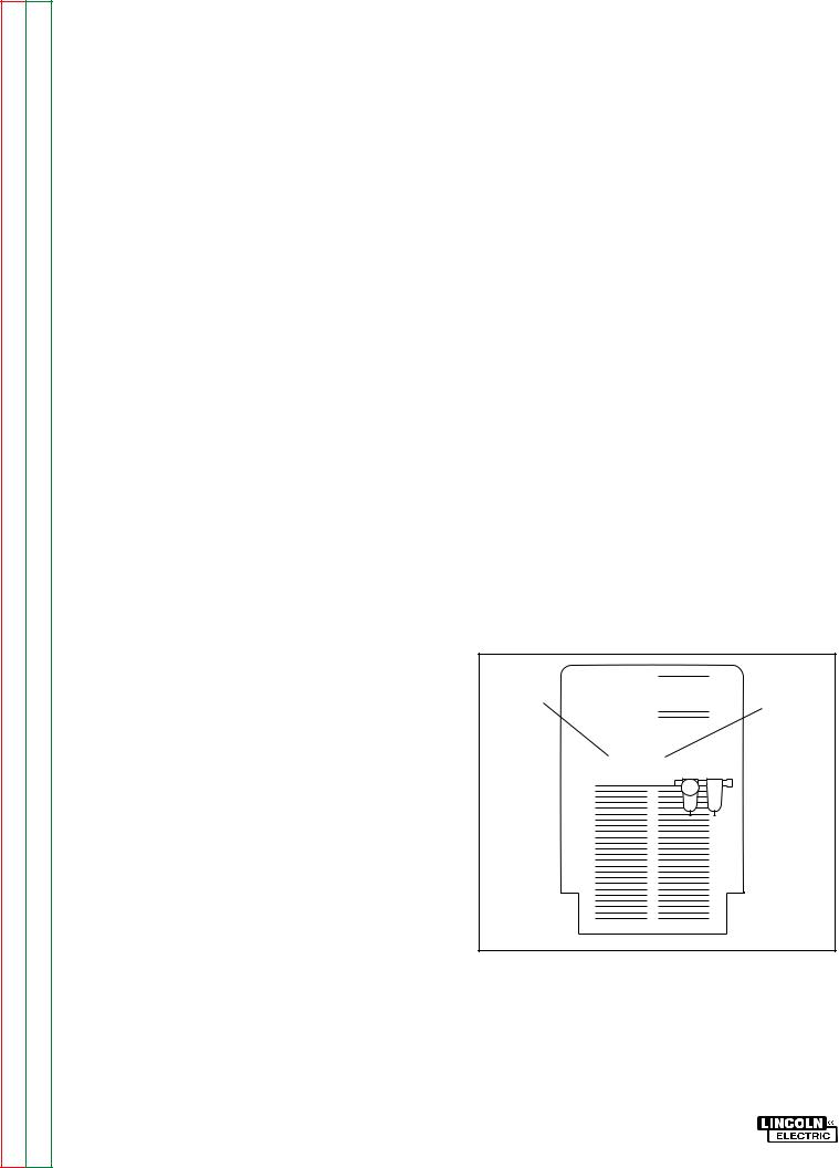
Before installing the machine, check that input supply voltage, phase, and frequency are the same as the machine's voltage, phase, and frequency as specified on the machine's rating plate on the Case Front Assembly. See Figure A.1 for the location of the machine's input cable entry opening, terminal block, and reconnect panel assembly. Input power supply entry is through the hole in the Case Back Assembly.


FIGURE A.1 - Case Back Assembly
1.Input Supply Cable Entry Opening
2.Terminal Block
3.Reconnect Panel Assembly
4.Air Pressure Regulator.
PRO-CUT 60
Return to Section TOC |
Return to Master TOC |
Return to Section TOC |
Return to Master TOC |
Return to Section TOC |
Return to Master TOC |
Return to Section TOC |
Return to Master TOC |
INSTALLATION |
A-4 |
FUSE AND WIRE SIZES
Protect the input circuit with the super lag fuses or delay type circuit breakers listed on the Specifications page of this manual for the machine being used. The tripping action of delay type circuit breakers decreases as the magnitude of the current increases. They are also called inverse time or thermal/magnetic circuit breakers.
DO NOT use fuses or circuit breakers with a lower amp rating than recommended. This can result in "nuisance" tripping caused by inrush current even when machine is not being used for cutting or gouging at high output currents.
Use input and grounding wire sizes that meet local electrical codes or see the Specifications page in this manual.
GROUND CONNECTION
Ground the frame of the machine. A ground terminal marked with the symbol ( ) is located at the left side of the Input Box Assembly. Access to the Input Box Assembly is at the top-rear of the machine. See your local and national electrical codes for proper grounding methods.
INPUT POWER SUPPLY CONNECTIONS
A qualified electrician should connect the input power supply leads to the L1 and L2 terminals on the Input Box Assembly Terminal Block.
1.Follow all national and local electrical codes.
2.Follow Input Supply Connection Diagram located on the inside of the access door.
3.Use a single-phase line or one phase of a three-phase line.
4.Connect leads to machine's terminal block. See Figure A.2.
a.For #8 AWG wire (8.4mm), connect leads directly to machine's terminal block.
b.For #10 AWG wire (5.3mm), connect leads to terminal block using the ferrules (S19117-1)provided.
(1)Strip 1/2" (12.7mm) of insulation from wire.
(2)Place ferrule over wire.
(3)Connect to machine terminal block.
c.Tighten screws to 16 in/lbs (1.8 N.M.)
GND.
L1 L2
TERMINAL
BLOCK
|
|
|
RECONNECT |
||
|
|
|
PANEL ASSEMBLY |
||
For #10 (5.3mm2) |
.50" |
|
|
||
AWG Wire Only |
|
(12.7 mm) |
|||
|
|
|
|
|
|
|
|
|
|
|
|
|
|
|
|
|
|
|
|
|
|
|
|
|
Strip #10 (5.3mm2) Wire |
||||
Place Ferrule (S19117-1) Over Wire as Shown
Before Insertion into Machine Terminal Block.
FIGURE A.2 - Input Power Supply
Connections.
PRO-CUT 60

Return to Section TOC |
Return to Master TOC |
Return to Section TOC |
Return to Master TOC |
Return to Section TOC |
Return to Master TOC |
Return to Section TOC |
Return to Master TOC |
A-5 |
INSTALLATION |
AIR INPUT CONNECTIONS
Supply the PRO-CUT 60 with clean compressed air or nitrogen.
•Supply pressure must be between 70 psi and 120 psi (482 kPa and 827 kPa).
•Flow rate should be approximately 4.7 cfm (133 I/min.).
NOTE: Oil in the air supply to the PRO-CUT 60 can cause severe problems. Use only a clean air supply.
1.Connect the air supply to the PRO-CUT 60 regulator.
a.Remove the plastic thread protector from the machine's regulator input port located on the back of the machine. Refer to figure A.1.
-The input port is a 1/4" (6.3mm) NPT thread.
b.Connect the air supply to the machine regulator with an appropriate gas connection fitting. Sealing the connection with Teflon tape is recommended.
2.Tighten the air fitting connection to prevent leakage.
-Do not overtighten.
NOTE: When using nitrogen gas from a cylinder, the cylinder must have a pressure regulator.
•Maximum psi from nitrogen gas cylinder to PRO-CUT 60 regulator should never exceed 120 psi (827 kPa).
•Install a hose between the nitrogen gas cylinder regulator and the PRO-CUT 60 regulator's gas inlet.
 WARNING
CYLINDER could explode if damaged.
•Keep cylinder upright and chained to a fixed support.
•Keep cylinder away from areas where it could be damaged.
•Never lift machine with cylinder attached.
•Never allow the cutting torch to touch the cylinder.
•Keep cylinder away from live electrical parts.
•Maximum inlet pressure 120 psi (827kPa).
__________________
PRO-CUT 60
|
|
|
INSTALLATION |
|
A-6 |
|
TOC |
TOC |
|
|
|
|
|
Section |
Master |
|
|
460V |
|
|
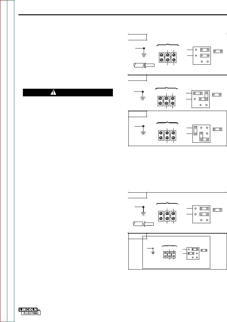
RECONNECT PROCEDURE |
460 V., 60HZ. |
LINK POSITIONS |
||||
|
|
|
||||
to |
to |
GND. |
|
LINK |
||
|
|
L2 |
||||
Return |
Return |
|
|
L1 |
|
|
Multiple voltage machines are shipped connected |
|
|
|
|||
to the highest input voltage listed on the |
|
|
|
|||
|
|
machine's rating plate. |
Before installing the |
|
|
|
|
|
machine, check that the Reconnect Panel in the |
USE FERRULE |
|
|
|
|
|
#10 AWG ONLY |
|
|
||
|
|
Input Box Assembly is connected for the proper |
230V |
|
|
|
|
|
voltage. |
|
|
|
|
|
|
|
230 V., 60HZ. |
LINK POSITIONS |
||
|
|
|
|
|||
|
|
CAUTION |
GND. |
|
LINK |
|
|
|
L1 |
L2 |
|||
|
|
|
||||
|
|
|
|
|
||
TOC |
TOC |
Failure to follow these instructions can cause |
|
|
|
|
immediate failure of components within the |
|
|
|
|||
Section |
Master |
|
|
|
||
machine. |
|
208V |
|
|
||
__________________ |
208 V., 60HZ. |
LINK POSITIONS |
||||
GND. |
|
LINK |
||||
to |
to |
|
||||
|
|
L1 |
L2 |
|
||
Return |
Return |
To reconnect the machine to a different voltage, |
|
|
|
|
change the position of the power straps (links) on |
|
|
|
|||
|
|
|
|
|
||
|
|
the reconnect panel assembly. Follow The Input |
|
|
|
|
|
|
Supply Connection Diagram located on the inside |
|
|
|
|
|
|
of the access door. |
|
|
|
|
|
FIGURE A.3a-Voltage Link Positions for |
1. For 208/230/460 VAC machines, see |
208/230/460 VAC machines. |
Figure A.3a. |
|
TOC |
TOC |
2. For 460/575 VAC machines, see Figure |
|
|
|
|
|
|
|
Section |
Master |
A.3b. |
|
|
575V |
|
|
||
|
|
|
|
|
|
|
575 V., 60HZ. |
LINK POSITIONS |
|
to |
to |
GND. |
L2 |
LINK |
L1 |
||||
|
|
|
|
|
Return |
Return |
|
|
|
|
|
USE FERRULE |
|
|
|
|
#10 AWG ONLY |
|
|
|
|
460V |
|
|
|
|
460 V., 60HZ. |
LINK POSITIONS |
|
|
|
GND. |
|
LINK |
|
|
L1 |
L2 |
|
|
|
|
||
TOC |
TOC |
|
|
|
Sectionto |
toMaster |
460/575 VAC machines. |
|
|
|
|
FIGURE A.3b - Voltage Link Positions for |
||
Return |
Return |
|
|
|
|
|
|
|
PRO-CUT 60 |
Return to Section TOC |
Return to Master TOC |
Return to Section TOC |
Return to Master TOC |
Return to Section TOC |
Return to Master TOC |
Return to Section TOC |
Return to Master TOC |
A-7 |
INSTALLATION |
OUTPUT CONNECTIONS
 WARNING
To avoid receiving a high frequency shock, keep the torch and cables in good condition.
__________________
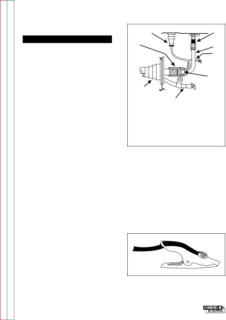
The standard PRO-CUT 60 cutting torch comes with a 25 ft. (7.6m) cable. A cutting torch with a 50 ft. (15.2m) cable is available. The PRO-CUT 60 is shipped with the torch and work cables already connected. Should you have to connect the torch or work cables, use the following procedure:
See Figure A.4 for the location of torch and work connections.
Connect cutting torch to machine. See Figure A.4.
1.Turn OFF Power Line switch.
2.Disconnect input power to the machine.
3.Insert the torch cable into the machine through the cable boot (8).
a.Insert enough torch cable to make all connections.
4.Turn and lock strain relief clamp (1) onto bolt to secure the gas line.
5.Connect the gas line fitting to the brass union and tighten with a wrench.
6.Connect to pilot lead (5) to terminal marked “PILOT”.
7.Connect work lead (7) to terminal marked “WORK”.
|
|
|
|
|
|
|
PILOT |
|
|
|
WORK |
|
|
Strain Relief Clamp |
Pilot Lead |
4-Pin Connector |
Bolt |
Bulkhead Connector |
Work Lead |
(Brass Fitting) |
Cable Boot |
Gas Line |
|
FIGURE A.4. -- Connect Torch Cable To
Machine
Connect work clamp to work clamp cable, which extends from the front of the machine. See Figure A.5.
1.Insert the cable through the hole at the end of the work clamp handle.
2.Pull the work clamp cable through the hole until it reaches the nut and bolt assembly.
3.Tighten the nut and bolt.
8. Connect 4-pin connector (2).
FIGURE A.5. -- Connect Work Clamp
PRO-CUT 60

Return to Master TOC
Return to Master TOC
Return to Master TOC
Return to Master TOC
TABLE OF CONTENTS |
Section B |
- OPERATION SECTION - |
|
|
|
|
Page |
Operation ............................................................................................................... |
Section B |
Safety Precautions ...................................................................................................... |
B-1 |
General Description ..................................................................................................... |
B-2 |
Recommended Processes and Equipment ................................................................... |
B-2 |
Operational Features and Controls .............................................................................. |
B-2 |
Design Features and Advantages ................................................................................ |
B-2 |
Cutting and Gouging Capability .................................................................................. |
B-3 |
Limitations .................................................................................................................... |
B-3 |
Controls and Settings ................................................................................................... |
B-3 |
Operating Steps .......................................................................................................... |
B-4 |
Cutting Procedure Recommendations ........................................................................ |
B-5 |
Pilot Arc.................................................................................................................... |
B-5 |
Cutting and Gouging Recommendations................................................................. |
B-5 |
Cutting Thin Metal.................................................................................................... |
B-6 |
Cutting Expanded Metal .......................................................................................... |
B-7 |
Cutting Thick Metal .................................................................................................. |
B-7 |
Gouging Metal ......................................................................................................... |
B-8 |
PRO-CUT 60
Return to Section TOC |
Return to Master TOC |
Return to Section TOC |
Return to Master TOC |
Return to Section TOC |
Return to Master TOC |
Return to Section TOC |
Return to Master TOC |
B-1 |
OPERATION |
SAFETY PRECAUTIONS - Read and understand entire section before operating machine.
 WARNING
ELECTRIC SHOCK can kill.
•Do not touch electrically live parts or electrode with skin or wet clothing.
•Insulate yourself from work and ground.
•Always wear dry insulating gloves.
FUMES AND GASES can be dangerous.
• Keep your head out of fumes.
•Use ventilation or exhaust to remove fumes from breathing zone.
WELDING, CUTTING and GOUGING SPARKS
can cause fire or explosion
•Keep flammable material away.
•Do not weld, cut or gouge on containers that have held combustibles.
ARC RAYS can burn.
•Wear eye, ear and body protection.
PLASMA ARC can injure
•Keep your body away from nozzle and plasma arc.
•Operate the pilot arc with caution. The pilot arc is capable of burning the operator, others or even piercing safety clothing.
Observe additional Safety Guidelines detailed in the beginning of this manual.
PRO-CUT 60

Return to Section TOC |
Return to Master TOC |
Return to Section TOC |
Return to Master TOC |
Return to Section TOC |
Return to Master TOC |
Return to Section TOC |
Return to Master TOC |
OPERATION |
B-2 |
GENERAL DESCRIPTION
The PRO-CUT 60 is a constant current, single range, continuous control plasma cutting system. The microprocessor-based PRO-CUT 60 is capable of cutting with compressed air or nitrogen gas. Nitrogen gas is used to cut aluminum or other non-ferrous metals. This sophisticated system has excellent starting characteristics, cutting visibility, and arc stability. The machine automatically performs fundamental troubleshooting when turned ON.
The PRO-CUT 60 is equipped with a patented plasma torch that has a safety mechanism that assures consumables are in place before cutting or gouging. This is extremely important due to the high voltages involved. Two standard torch cable lengths are available: a 25 ft. (7.6m) torch cable or a 50 ft. (15.2m) torch cable. The machine also comes with an air regulator, coarse air filter, pressure gage, and spare parts kit. The standard undercarriage is shipped assembled, except for the handle.
RECOMMENDED PROCESSES AND EQUIPMENT
The PRO-CUT 60 is capable of all cutting and gouging applications within its output capacity of 25 to 60 amps. These applications include thin gage sheet metal and expanded metal.
OPERATIONAL FEATURES AND CONTROLS
The PRO-CUT 60 comes with an ON/OFF POWER SWITCH, OUTPUT CURRENT CONTROL, and a RUN/PURGE SWITCH.
DESIGN FEATURES AND
ADVANTAGES
The microprocessor controlled PRO-CUT 60 design makes plasma cutting and gouging tasks uncomplicated. This list of design features and advantages will help you understand the machine's total capabilities so that you can get maximum use of your machine.
•Single continuous output range of 25-60 amps.
•Microprocessor controlled overshooting limiting function increases consumable life.
•High intensity, high frequency starter.
•Unique microprocessor controlled starting sequence for consistent starting and torch protection.
•Solid state pilot duty cycle limiting.Protects components without fuses that would have to be replaced.
•Bright 2.5-second timed pilot arc.
•Purge/Run switch.
•Two independent mechanisms for sensing a shorted torch. Needed for safety and torch protection.
•Patented safety sensor monitors if torch parts are in place.
•Latching safety circuit mechanism requires that the operator reset the circuit.
•Exposed torch parts voltage monitoring with safety shutdown.
•Built-in undercarriage for portability.
•Built-in air controls, including air pressure regulator.
•Air line filtering.
•Preflow/Afterflow timing. Preflow stops if cutting or gouging resumes in previous afterflow.
•Easy to use torch trigger switch.
•Line voltage compensated.
•Thermostatically protected.
•Solid state overcurrent protection.
PRO-CUT 60

Return to Section TOC |
Return to Master TOC |
Return to Section TOC |
Return to Master TOC |
Return to Section TOC |
Return to Master TOC |
Return to Section TOC |
Return to Master TOC |
B-3 |
OPERATION |
•Works with pure nitrogen for cutting non-ferrous metal.
•Smart switching of pilot contactor so that it does not switch under load.
•Low fan noise at idle.
•Modular construction for easy servicing.
CUTTING AND GOUGING
CAPABILITY
The PRO-CUT 60 is rated at 60 amps, 115 VAC, at 60% duty cycle on a 10 minute basis or 45 amps, 115VAC, at 100% duty cycle. If the duty cycle is exceeded, a thermal protector will shut off the output of the machine until it cools to the normal operating temperature.
LIMITATIONS
Do not exceed output current and duty cycle rating of machine. Do not use the PRO-CUT 60 for pipe thawing.
CONTROLS AND SETTINGS
All operator controls and adjustments are located on the Case Front Assembly of the PRO-CUT 60. See Figure B.1 for the location of each control.
1.SAFETY RESET BUTTON:The SAFETY RESET BUTTON is pressed to resume operation after the SAFETY LED glows and the operating problem is cleared.
2.PURGE/RUN SWITCH: This switch controls the air supply to the machine. In the PURGE position, air flows continuously through the torch to allow for the adjustment of air pressure. Note that the output is disabled in this mode. In the RUN position, air flows through the torch when the torch trigger is activated.
3.STATUS LED DISPLAY: The following machine conditions are displayed:
MACHINE ON LED: The green POWER ON LED glows when the POWER LINE SWITCH is in the ON position and AC power is connected to the machine.
OUTPUT ON LED: The OUTPUT ON LED glows when the pilot arc starts and remains glowing during cutting.
AIR PRESSURE LED: The AIR PRESSURE LED glows whenever there is adequate air pressure (above 50 psi).
THERMAL LED: The THERMAL LED glows when the machine overheats.
FAULT LED (MALFUNCTION LED): The FAULT LED glows/blinks if a short circuit has occurred in the torch, in the machine, or when the air pressure is too low.
SAFETY LED: The SAFETY LED glows when there is an operating problem with the machine, torch, or torch consumables.
4.OUTPUT CURRENT CONTROL: The OUTPUT CURRENT CONTROL adjusts the current flow for maximum cutting results. See User Chart Range guide on machine's nameplate for recommended range settings based on thickness of steel being cut.
5.ON/OFF POWER SWITCH: Turns the machine ON or OFF.
PRO-CUT 60

|
|
|
|
|
OPERATION |
B-4 |
TOC |
TOC |
|
|
|
|
|
Return to Section |
Return to Master |
|
|
|
||
|
|
|
|
|
||
|
|
|
|
|
|
|
to Section TOC |
to Master TOC |
|
|
|
|
|
Return |
Return |
1. |
Safety Reset Button, |
2. |
Purge/Run Switch, |
3. Status LED Display, |
4. |
Output Current Control, |
5. |
ON/OFF Power Switch |
|
||
|
|
|
FIGURE B.1 Control Panel Keys
|
|
|
|
|
NOTE: If the SAFETY LED glows, press the |
|
TOC |
TOC |
OPERATING STEPS |
|
|
SAFETY RESET button. If there is no prob- |
|
|
|
lem, the SAFETY LED will go off. If the SAFE- |
||||
|
|
|
||||
|
|
|
|
|
||
Section |
Master |
When preparing to cut or gouge, position the |
TY LED remains on, turn the ON/OFF |
|||
POWER SWITCH to OFF and refer to the |
||||||
sure you have all materials needed to complete |
||||||
|
|
machine as close to the work as possible. Make |
TROUBLESHOOTING GUIDE in the TROU- |
|||
|
|
|
|
|
||
to |
to |
the job and have taken all safety precautions. It is |
BLESHOOTING AND REPAIR SECTION of |
|||
this manual for a recommended course of |
||||||
Return |
Return |
important to follow these operating steps each |
||||
action. |
||||||
|
|
|||||
|
|
time you use the machine. |
|
|
||
|
|
|
|
|
||
|
|
1. Turn the machine's |
ON/OFF |
POWER |
5. Set the PURGE/RUN switch in the PURGE |
|
|
|
position. |
||||
|
|
SWITCH to OFF position. |
|
|
||
|
|
|
|
- The air flow starts. |
||
|
|
|
|
|
||
|
|
2. Connect air supply to the machine. |
|
- The AIR PRESSURE LED glows. |
||
|
|
|
|
|||
|
|
3. Turn on main AC power supply |
to the |
6. Adjust air pressure to 60 psi with the air |
||
|
|
flowing. |
||||
TOC |
TOC |
machine. |
|
|
||
|
|
|
||||
4. Turn the machine's |
ON/OFF |
POWER |
7. Move the PURGE/RUN SWITCH to RUN. |
|||
Section |
Master |
|||||
-Postflow air flows for 20 seconds. |
||||||
SWITCH to ON. |
|
|
||||
|
|
|
|
|||
|
|
|
|
|
||
to |
to |
- The green POWER ON LED glows. |
|
During this time, the pilot arc immediately |
||
|
starts when the torch trigger is pulled. After |
|||||
Return |
Return |
- The fan starts. |
|
|
||
|
|
20 seconds, air preflows for two seconds. |
||||
|
|
|
|
|||
|
|
|
|
|
||
|
|
|
|
|
PRO-CUT 60 |
|

Return to Section TOC |
Return to Master TOC |
Return to Section TOC |
Return to Master TOC |
Return to Section TOC |
Return to Master TOC |
Return to Section TOC |
Return to Master TOC |
B-5 |
OPERATION |
8.Pull the torch trigger to cut. - OUTPUT ON LED glows.
If postflow has not timed out, the pilot arc lights immediately.
If postflow air has timed out (after 20 seconds), air preflows for two seconds before pilot arc lights.
If the arc is not transferred by bringing plasma in contact with the work with in 2.5 seconds, the pilot arc shuts off.
9.Make a cut.
10.Stop cutting by releasing the torch trigger.
-Arc stops.
-Postflow air continues for 20 seconds.
-To continue cutting, repeat Step 8.
11.Turn ON/ OFF POWER SWITCH to OFF when job is done.
If the SAFETY LED glows at any time during operation, check the following:
-Torch consumables are assembled properly. Machine will not start if they are not properly in place.
-Nozzle condition. The nozzle must be clean.
After the problem is corrected or no problem is found, press the SAFETY RESET button. If SAFETY LED goes out, machine is ready for use. If SAFETY LED continues to glow, refer to the TROUBLESHOOTING GUIDE in the TROUBLESHOOTING AND REPAIR SECTION of this manual for a recommended course of action.
CUTTING PROCEDURE
RECOMMENDATIONS
For best results, use proper cutting or gouging procedures. Plasma arc cutting is a very economical process when used properly. Improper procedures or equipment use will result in poor quality work and high operating costs. The following procedures will help you get maximum performance from your PRO-CUT 60.
Use Pilot Arc Properly
The pilot arc transfers the arc to the work piece for cutting. Do not start the pilot arc repeatedly over short periods of time. This could reduce consumable life. Start the pilot arc and then make and finish the cut before releasing the trigger.
If the pilot arc sputters or does not start each time the torch trigger is pulled, check the consumable for wear or high air pressure. If either is found, take proper action.
Cutting and Gouging Recommendations
General
1. Make a continuous cut. Do not pause during cutting, gouging, or at the end of the work piece. Stopping and starting causes poor cuts and results in poor machine operation. In addition, it reduces consumable life.
2. Position the torch so that dross and hot air cannot be deflected into the torch.
3.Do not drag the nozzle when cutting above the mid-range setting. Above mid range, always hold the torch 1/8" away from the work piece.
4.Proper drag cup/shield cup use gives you maximum nozzle and consumable life.
-When operating in the blue or red current ranges, use a drag cup when possible.
-When operating in the yellow range, use a drag cup or a shield cup.
5.Use the proper machine setting for the
work to be done. Adjusting the machine to maximum output does not produce the best cutting in most situations.
PRO-CUT 60
Return to Section TOC |
Return to Master TOC |
Return to Section TOC |
Return to Master TOC |
Return to Section TOC |
Return to Master TOC |
Return to Section TOC |
Return to Master TOC |
OPERATION |
B-6 |
6.Use nozzle with the largest orifice that gives the best cut for the work being done. This produces the best work results and consumable life. As the size of the nozzle orifice increases, its current capability increases. Therefore, the nozzle used for cutting or gouging work must be able to handle the current needed to give the best cutting results. A nozzle working beyond its current capability overheats causing poor performance. Never use the .035 inch (0.8mm) nozzle when the current output is above the yellow current range.
7.Use the S24114 Drag Cup when the output current is in the red range to protect the torch from dross and the effects of improper arcing conditions.
NOTE: The S24114 Drag Cup should not be used at very low outputs.
8.Do not allow your body or the torch cable to touch hot surfaces.
9.Refer to the User Chart Range guide on the machine's nameplate for recommended output current ranges for the thickness of the metal being cut.
Cutting Thin Gauge Sheet Metal
1.Set the OUTPUT CURRENT CONTROL output at mid-range (Yellow range) or below.
2.Pierce a hole in the metal surface to start the cut. Then, lightly touching the nozzle to the metal surface, drag the torch along the cut line.
3.Use the .035" (0.8mm) nozzle for fine cuts. Larger nozzle sizes work better and provide longer life, but produce wider kerfs (cuts.)
4.Use a current level setting that is adequate to produce an acceptable cut at maximum travel speed. Operating at a current level that exceeds the requirements needed to cut the metal results in poor cutting quality and machine operation.
5.Cut thin gage sections of aluminum, copper, and other non-ferrous metals using a higher current range. If acceptable results are not obtained, use the procedures listed under Cutting Thick Sections of Metal.
3/99
PRO-CUT 60
Return to Section TOC |
Return to Master TOC |
Return to Section TOC |
Return to Master TOC |
Return to Section TOC |
Return to Master TOC |
Return to Section TOC |
Return to Master TOC |
B-7 |
OPERATION |
Cutting Expanded Metal
1.Cut expanded metal with OUTPUT CURRENT CONTROL set near the midrange position using the same methods listed under Cutting Thin Gauge Metal. Keep the following points in mind:
a.Place a thin piece of scrap metal over the area to be cut and then cut through both to make cutting easier.
b.After 30 seconds of cutting expanded metal, the pilot arc changes from a
bright continuous arc to an arc that rapidly goes on and off. This produces a slight spatter. You can still cut metal when this condition occurs as long as metal has been cut in the last five seconds. If metal is not cut in this condition for more than five seconds, the arc shuts off and the machine goes into postflow.
c.The pilot arc duty cycle is 20 seconds out 80 seconds. If the torch trigger is continuously pulled and released to
obtain a bright, continuous arc, the duty cycle limit will be reached and the arc will be turned off for the duty cycle limit. When the arc is turned off, the OUTPUT ON and FAULT LEDs flash alternately.
Cutting Thick Sections of Metal
1.Set the OUTPUT CURRENT CONTROL above the mid-range (Red) position.
a.Use the minimum current needed to make a satisfactory cut.
2.Hold the torch nozzle about 1/8" (3.2mm) from the cutting surface. Do not let the torch nozzle touch the work or carry a long arc.
a.Use the S24114 Drag Cup to protect the torch.
b.Use only the .052" (1.3mm) or the .042" (1.0mm) nozzles. Do not use the .035" (0.8mm) nozzle for cutting thick sections of metal.
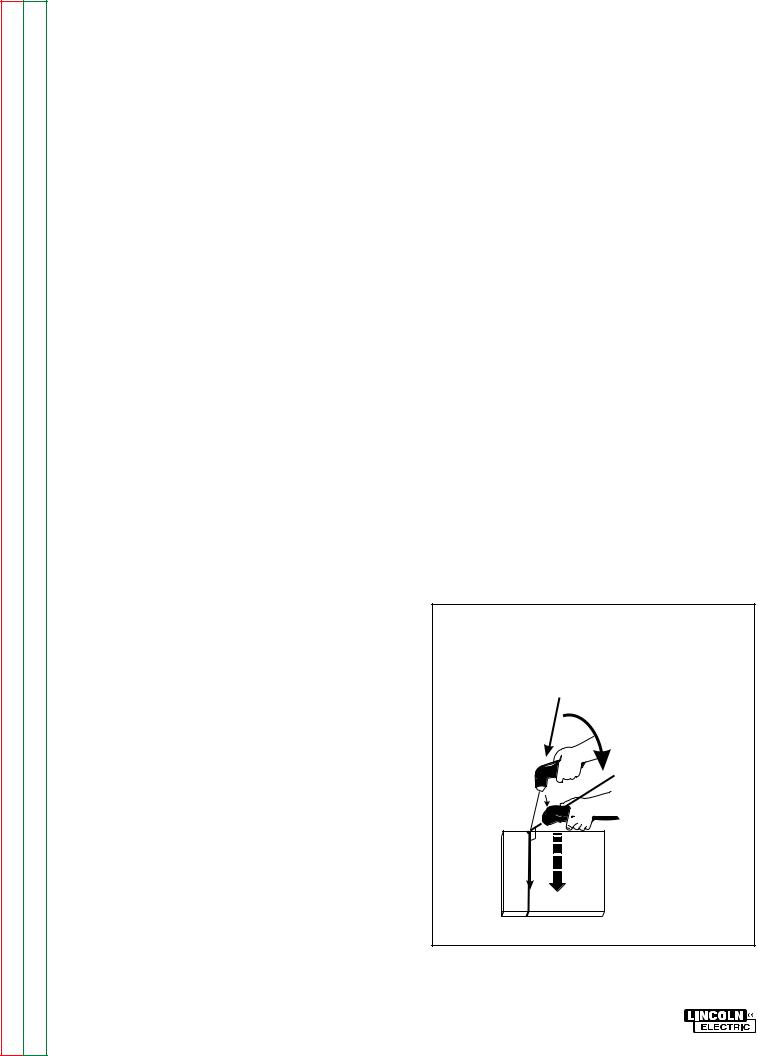
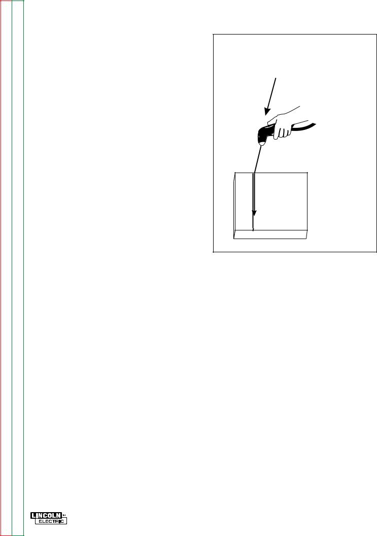
3.Start the cut from the edge of the work piece when possible. Pierce the work piece by slowly lowering the torch onto the metal at a 300 angle. This will blow the dross away from the torch tip. Slowly rotate the torch to vertical position as the arc becomes deeper. See Figure B. 2.
4.Keep moving while cutting. Cut at a steady speed without pausing.
TORCH AT 300 ANGLE
TO PIERCE
|
ROTATE TO |
300 |
900 ANGLE TO CUT |
90VERTICAL ANGLE FOR CUTTING
CUT
FIGURE B.2 -- Cutting Thick Piece of Metal.
3/99
PRO-CUT 60
Return to Section TOC |
Return to Master TOC |
Return to Section TOC |
Return to Master TOC |
Return to Section TOC |
Return to Master TOC |
Return to Section TOC |
Return to Master TOC |
OPERATION |
B-8 |
Gouging Metal
1.Set the OUTPUT CURRENT CONTROL to maximum.
2. Use the plasma torch with a S24114 Drag Cup assembly or a S24162 shield cup.
3. Bring the torch slowly towards the work piece at a 300 angle, but do not pierce the work piece. Do not touch the nozzle to the work piece. See Figure B.3.
a.Blow molten metal away from the torch.
b.If needed, raise the air pressure to
approximately 75 psi to help blow away molten metal.
c.This process will blow a lot of molten metal and dross. BE CAREFUL! Blow the dross away from the torch, away from the operator and away from flammable objects.
d.Do not allow the torch cable or body to contact hot surfaces.
e.Performance is similar to air carbon arc gouging with a 1/8” (3.2mm) carbon electrode.
ANGLE
OF APPROACH
TORCH HELD AT
300 ANGLE
THROUGHOUT GOUGE
ANGLE
MAINTAINED
THROUGHOUT
GOUGE
FIGURE B.3 -- Gouging Metal.
3/99
PRO-CUT 60

Return to Section TOC |
Return to Section TOC |
Return to Section TOC |
Return to Section TOC |
|
|
|
|
Return to Master TOC |
Return to Master TOC |
Return to Master TOC |
Return to Master TOC |
|
|
|
|
-PRO |
|
|
9-B |
60 CUT |
|
|
|
NOTES

Return to Master TOC
Return to Master TOC
Return to Master TOC
Return to Master TOC
TABLE OF CONTENTS |
Section C |
- ACCESSORIES SECTION - |
|
|
|
|
Page |
Accessories............................................................................................................ |
Section C |
Accessories.................................................................................................................... |
C-1 |
PRO-CUT 60

|
|
C-1 |
ACCESSORIES |
|
|
TOC |
TOC |
OPTIONS/ACCESSORIES |
|
||
|
|
||||
Section |
Master |
The drag cup protects the torch by preventing the |
|||
|
|
|
DRAG CUP ASSEMBLY (S24114) |
|
|
to |
to |
torch from touching the workpiece. |
|
||
Return |
Return |
This shields the torch tip and provides more visibil- |
|||
|
|
|
SHIELD CUP ASSEMBLY (S24162) |
|
|
|
|
|
ity to the workpiece than the drag cup. Note the |
||
|
|
|
shield cup does not prevent the torch tip from |
||
|
|
|
touching the workpiece. |
|
|
|
|
|
TORCH SPARE PARTS KIT (K872) |
|
|
|
|
|
(Included with each machine) |
|
|
TOC |
TOC |
Includes: |
|
||
Shield Cup Asmbly |
S24162 |
||||
Section |
Master |
||||
.035 (0.9mm) Orifice |
S18497-1D1 |
||||
|
|
|
Nozzles: |
|
|
to |
to |
|
S18497-2D1 |
||
Return |
Return |
.042 (1.1mm) Orifice |
|||
.052 (1.3mm) Orifice |
S18497-3D1 |
||||
.078 (Gouging) (2.0mm)Orifice |
S18497-4D1 |
||||
|
|
|
Electrode |
S18752D1 |
|
|
|
|
Drag Cup Asmbly |
S24114 |
|
TOC |
TOC |
Wrench |
S18808 |
||
Tool Box |
S19576-1 |
||||
SectiontoReturn |
MastertoReturn |
||||
1 These parts come in a 5-pack. |
|
||||
|
|
|
|
||
Return to Section TOC |
Return to Master TOC |
|
3/99 |
|
PRO-CUT 60 |

Return to Master TOC
Return to Master TOC
Return to Master TOC
Return to Master TOC
TABLE OF CONTENTS |
Section D |
- MAINTENANCE SECTION - |
|
|
|
|
Page |
Maintenance ..................................................................................................... |
Section D |
Safety Precautions ................................................................................................... |
D-1 |
Capacitor Discharge Procedure ...................................................................... |
D-1 - D-2 |
Routine and Periodic Maintenance .......................................................................... |
D-3 |
3-D Exploded View................................................................................................... |
D-4 |
PRO-CUT 60

Return to Section TOC |
Return to Master TOC |
Return to Section TOC |
Return to Master TOC |
Return to Section TOC |
Return to Master TOC |
Return to Section TOC |
Return to Master TOC |
D-1 |
MAINTENANCE |
SAFETY PRECAUTIONS
 WARNING
ELECTRIC SHOCK can kill.
• Only qualified personnel should perform this maintenance.
• Turn the input power OFF at the disconnect switch or fuse box before working on this equipment.
• Failure to follow this capacitor discharge procedure can result in electric shock.
• Do not touch electrically hot parts.
CAPACITOR DISCHARGE PROCEDURE
PROCEDURE DESCRIPTION
This procedure must be performed before performing any maintenance inside the machine.
MATERIALS NEEDED
High resistance, high wattage resistor
( 25-1000 ohms, 25 watts minimum). Insulated pliers
Insulated gloves
DC Volt/Ohm meter (Multimeter)
PRO-CUT 60
Return to Section TOC |
Return to Master TOC |
Return to Section TOC |
Return to Master TOC |
Return to Section TOC |
Return to Master TOC |
Return to Section TOC |
Return to Master TOC |
MAINTENANCE |
D-2 |
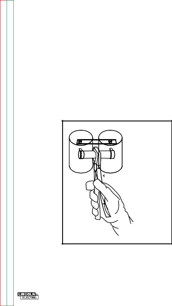
CAPACITOR DISCHARGE PROCEDURE
PROCEDURE
NOTE: See Figure D.1.
1.Disconnect input power to the machine.
2.Remove the Left Case Side Assembly.
3.Locate the two capacitors shown Figure D.1 and D.2.
4.Put on the insulated gloves.
5.Grip the middle of the resistor with the insulated pliers.
6.Touch the resistor leads across the two capacitor straps as shown for 10 seconds.
a.DO NOT TOUCH THE CAPACITOR STRAPS WITH YOUR HANDS OR ANY OTHER PART OF YOUR BODY.
7.Test for zero volts across the capacitor terminals with a DC voltmeter.
a.Capacitor terminal polarity is marked on the capacitor straps.
b.If any voltage is measured, REPEAT PROCEDURE.
 INSULATED
PLIERS
 INSULATED
GLOVES
FIGURE D.1 - Capacitor Discharge Procedure
PRO-CUT 60

Return to Section TOC |
Return to Master TOC |
Return to Section TOC |
Return to Master TOC |
Return to Section TOC |
Return to Master TOC |
Return to Section TOC |
Return to Master TOC |
D-3 |
MAINTENANCE |
ROUTINE AND PERIODIC
MAINTENANCE
1.Disconnect input power supply lines to the machine before performing periodic maintenance, tightening, cleaning, or replacing parts. See Figure D.2.
2.Perform Capacitor Discharge Procedure
Perform the following daily:
1.Check that no combustible materials are in the cutting or gouging area or around the machine.
2.Remove any debris or materials that could block the air flow to the machine for cooling.
3.Inspect the torch cable for any slits, puncture marks in the cable jacket, kinks, or any condition that could restrict air flow to the torch. Repair or replace when needed.
 WARNING
Perform Periodically:
Clean inside the machine with a low pressure air stream. Clean the following components. Refer to figure D.2.
•Main transformer
•Torch, pilot and work connections
•Spark gap (Inspect for .060 spacing)
•Control board
•Power board
•Heat sink fins
•Fan motor and blade
To avoid receiving a high frequency shock, keep the torch and torch cables in good condition.
Perform the following every three months or sooner:
1.Check air regulator filters (weekly in dirty environments).
a. If clogged or dirty, replace them.
PRO-CUT 60
 Loading...