


PRECISION TIG 275
PRECISION TIG 275
RETURN TO MAIN MENU
IM897
September, 2007
For use with machines having Code Numbers:
Safety Depends on You
Lincoln arc welding and cutting
equipment is designed and built
with safety in mind. However, your
overall safety can be increased by
proper installation ... and thoughtful
operation on your part. DO NOT
INSTALL, OPERATE OR REPAIR
THIS EQUIPMENT WITHOUT
READING THIS MANUAL AND
THE SAFETY PRECAUTIONS
CONTAINED THROUGHOUT.
And, most importantly, think before
you act and be careful.
11158; 11159
Cleveland, Ohio 44117-1199 U.S.A. TEL: 216.481.8100 FAX: 216.486.1751 WEB SITE: www.lincolnelectric.com
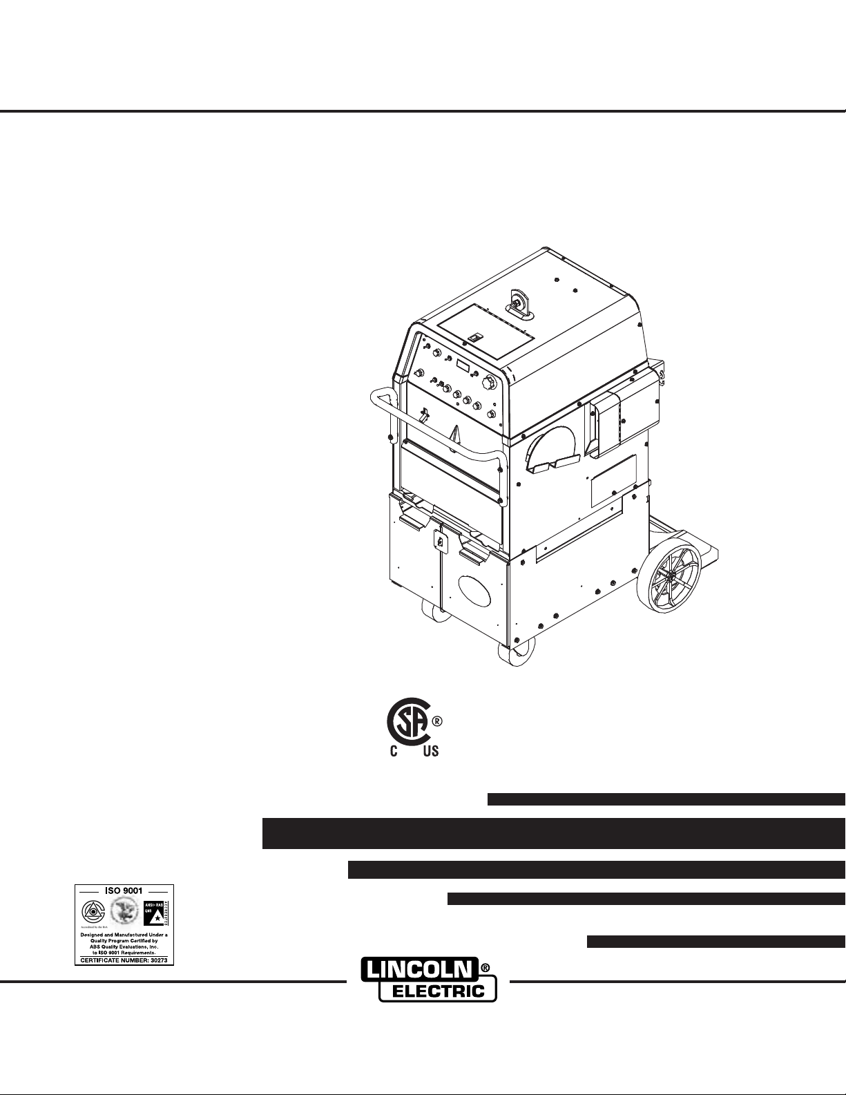
Precision TIG 275 Welding
Package shown with optional
Advanced Control Panel
IP21S
OPERATORʼS MANUAL
Copyright © 2007 Lincoln Global Inc.
• World's Leader in Welding and Cutting Products •
• Sales and Service through Subsidiaries and Distributors Worldwide •
i
SAFETY
WARNING
CALIFORNIA PROPOSITION 65 WARNINGS
For Diesel Engines: Diesel engine exhaust and
some of its constituents are known to the State
of California to cause cancer, birth defects, and
other reproductive harm.
ARC WELDING CAN BE HAZARDOUS. PROTECT YOURSELF AND OTHERS FROM POSSIBLE SERIOUS INJURY OR DEATH.
KEEP CHILDREN AWAY. PACEMAKER WEARERS SHOULD CONSULT WITH THEIR DOCTOR BEFORE OPERATING.
Read and understand the following safety highlights. For additional safety information, it is strongly recommended that you
purchase a copy of “Safety in Welding & Cutting - ANSI Standard Z49.1” from the American Welding Society, P.O. Box 351040,
Miami, Florida 33135 or CSA Standard W117.2-1974. A Free copy of “Arc Welding Safety” booklet E205 is available from the
Lincoln Electric Company, 22801 St. Clair Avenue, Cleveland, Ohio 44117-1199.
BE SURE THAT ALL INSTALLATION, OPERATION, MAINTENANCE AND REPAIR PROCEDURES ARE
PERFORMED ONLY BY QUALIFIED INDIVIDUALS.
For Gasoline Engines: The engine exhaust from
this product contains chemicals known to the
State of California to cause cancer, birth defects,
or other reproductive harm.
i
FOR ENGINE
powered equipment.
1.a. Turn the engine off before troubleshooting and maintenance
work unless the maintenance work requires it to be running.
____________________________________________________
1.b.Operate engines in open, well-ventilated
areas or vent the engine exhaust fumes
outdoors.
____________________________________________________
1.c. Do not add the fuel near an open flame weld-
ing arc or when the engine is running. Stop
the engine and allow it to cool before refueling to prevent spilled fuel from vaporizing on
contact with hot engine parts and igniting. Do
not spill fuel when filling tank. If fuel is spilled,
wipe it up and do not start engine until fumes
have been eliminated.
____________________________________________________
1.d. Keep all equipment safety guards, covers and devices in position and in good repair.Keep hands, hair, clothing and tools
away from V-belts, gears, fans and all other moving parts
when starting, operating or repairing equipment.
____________________________________________________
1.e. In some cases it may be necessary to remove safety
guards to perform required maintenance. Remove
guards only when necessary and replace them when the
maintenance requiring their removal is complete.
Always use the greatest care when working near moving
parts.
___________________________________________________
1.f. Do not put your hands near the engine fan.
Do not attempt to override the governor or
idler by pushing on the throttle control rods
while the engine is running.
1.h. To avoid scalding, do not remove the
radiator pressure cap when the engine is
hot.
ELECTRIC AND
MAGNETIC FIELDS
may be dangerous
2.a. Electric current flowing through any conductor causes
localized Electric and Magnetic Fields (EMF). Welding
current creates EMF fields around welding cables and
welding machines
2.b. EMF fields may interfere with some pacemakers, and
welders having a pacemaker should consult their physician
before welding.
2.c. Exposure to EMF fields in welding may have other health
effects which are now not known.
2.d. All welders should use the following procedures in order to
minimize exposure to EMF fields from the welding circuit:
2.d.1.
Route the electrode and work cables together - Secure
them with tape when possible.
2.d.2. Never coil the electrode lead around your body.
2.d.3. Do not place your body between the electrode and
work cables. If the electrode cable is on your right
side, the work cable should also be on your right side.
___________________________________________________
1.g. To prevent accidentally starting gasoline engines while
turning the engine or welding generator during maintenance
work, disconnect the spark plug wires, distributor cap or
magneto wire as appropriate.
2.d.4. Connect the work cable to the workpiece as close as
possible to the area being welded.
2.d.5. Do not work next to welding power source.
Mar ʻ95
ii
SAFETY
ii
ELECTRIC SHOCK can kill.
3.a. The electrode and work (or ground) circuits
are electrically “hot” when the welder is on.
Do not touch these “hot” parts with your bare
skin or wet clothing. Wear dry, hole-free
gloves to insulate hands.
3.b. Insulate yourself from work and ground using dry insulation.
Make certain the insulation is large enough to cover your full
area of physical contact with work and ground.
In addition to the normal safety precautions, if welding
must be performed under electrically hazardous
conditions (in damp locations or while wearing wet
clothing; on metal structures such as floors, gratings or
scaffolds; when in cramped positions such as sitting,
kneeling or lying, if there is a high risk of unavoidable or
accidental contact with the workpiece or ground) use
the following equipment:
• Semiautomatic DC Constant Voltage (Wire) Welder.
• DC Manual (Stick) Welder.
• AC Welder with Reduced Voltage Control.
3.c. In semiautomatic or automatic wire welding, the electrode,
electrode reel, welding head, nozzle or semiautomatic
welding gun are also electrically “hot”.
3.d. Always be sure the work cable makes a good electrical
connection with the metal being welded. The connection
should be as close as possible to the area being welded.
3.e. Ground the work or metal to be welded to a good electrical
(earth) ground.
3.f.
Maintain the electrode holder, work clamp, welding cable and
welding machine in good, safe operating condition. Replace
damaged insulation.
3.g. Never dip the electrode in water for cooling.
3.h. Never simultaneously touch electrically “hot” parts of
electrode holders connected to two welders because voltage
between the two can be the total of the open circuit voltage
of both welders.
3.i. When working above floor level, use a safety belt to protect
yourself from a fall should you get a shock.
3.j. Also see Items 6.c. and 8.
ARC RAYS can burn.
4.a. Use a shield with the proper filter and cover
plates to protect your eyes from sparks and
the rays of the arc when welding or observing
open arc welding. Headshield and filter lens
should conform to ANSI Z87. I standards.
4.b. Use suitable clothing made from durable flame-resistant
material to protect your skin and that of your helpers from
the arc rays.
4.c. Protect other nearby personnel with suitable, non-flammable
screening and/or warn them not to watch the arc nor expose
themselves to the arc rays or to hot spatter or metal.
FUMES AND GASES
can be dangerous.
5.a. Welding may produce fumes and gases
hazardous to health. Avoid breathing these
fumes and gases. When welding, keep
your head out of the fume. Use enough
ventilation and/or exhaust at the arc to keep
fumes and gases away from the breathing zone. When
welding with electrodes which require special
ventilation such as stainless or hard facing (see
instructions on container or MSDS) or on lead or
cadmium plated steel and other metals or coatings
which produce highly toxic fumes, keep exposure as
low as possible and below Threshold Limit Values (TLV)
using local exhaust or mechanical ventilation. In
confined spaces or in some circumstances, outdoors, a
respirator may be required. Additional precautions are
also required when welding on galvanized steel.
5. b. The operation of welding fume control equipment is affected
by various factors including proper use and positioning of the
equipment, maintenance of the equipment and the specific
welding procedure and application involved. Worker exposure level should be checked upon installation and periodically thereafter to be certain it is within applicable OSHA PEL
and ACGIH TLV limits.
5.c.
Do not weld in locations near chlorinated hydrocarbon
coming from degreasing, cleaning or spraying operations.
The heat and rays of the arc can react with solvent vapors
form phosgene, a highly toxic gas, and other irritating products.
5.d. Shielding gases used for arc welding can displace air and
cause injury or death. Always use enough ventilation,
especially in confined areas, to insure breathing air is safe.
vapors
to
5.e. Read and understand the manufacturerʼs instructions for this
equipment and the consumables to be used, including the
material safety data sheet (MSDS) and follow your
employerʼs safety practices. MSDS forms are available from
your welding distributor or from the manufacturer.
5.f. Also see item 1.b.
AUG 06
iii
SAFETY
iii
WELDING SPARKS can
cause fire or explosion.
6.a.
Remove fire hazards from the welding area.
If this is not possible, cover them to prevent
the welding sparks from starting a fire.
materials from welding can easily go through small cracks
and openings to adjacent areas. Avoid welding near
hydraulic lines. Have a fire extinguisher readily available.
6.b. Where compressed gases are to be used at the job site,
special precautions should be used to prevent hazardous
situations. Refer to “Safety in Welding and Cutting” (ANSI
Standard Z49.1) and the operating information for the
equipment being used.
6.c. When not welding, make certain no part of the electrode
circuit is touching the work or ground. Accidental contact can
cause overheating and create a fire hazard.
6.d. Do not heat, cut or weld tanks, drums or containers until the
proper steps have been taken to insure that such procedures
will not cause flammable or toxic vapors from substances
inside. They can cause an explosion even
been “cleaned”. For information, purchase “Recommended
Safe Practices for the
Containers and Piping That Have Held Hazardous
Substances”, AWS F4.1 from the American Welding Society
(see address above).
6.e. Vent hollow castings or containers before heating, cutting or
welding. They may explode.
Sparks and spatter are thrown from the welding arc. Wear oil
6.f.
free protective garments such as leather gloves, heavy shirt,
cuffless trousers, high shoes and a cap over your hair. Wear
ear plugs when welding out of position or in confined places.
Always wear safety glasses with side shields when in a
welding area.
6.g. Connect the work cable to the work as close to the welding
area as practical. Work cables connected to the building
framework or other locations away from the welding area
increase the possibility of the welding current passing
through lifting chains, crane cables or other alternate circuits.
This can create fire hazards or overheat lifting chains or
cables until they fail.
6.h. Also see item 1.c.
6.I. Read and folllow NFPA 51B “ Standard for Fire Prevention
During Welding, Cutting and Other Hot Work”, available from
NFPA, 1 Batterymarch Park,PO box 9101, Quincy, Ma
022690-9101.
Remember that welding sparks and hot
though
they have
Preparation
for Welding and Cutting of
CYLINDER may explode
if damaged.
7.a. Use only compressed gas cylinders
containing the correct shielding gas for the
process used and properly operating
regulators designed for the gas and
pressure used. All hoses, fittings, etc. should be suitable for
the application and maintained in good condition.
7.b. Always keep cylinders in an upright position securely
chained to an undercarriage or fixed support.
7.c. Cylinders should be located:
• Away from areas where they may be struck or subjected to
physical damage.
• A safe distance from arc welding or cutting operations and
any other source of heat, sparks, or flame.
7.d. Never allow the electrode, electrode holder or any other
electrically “hot” parts to touch a cylinder.
7.e. Keep your head and face away from the cylinder valve outlet
when opening the cylinder valve.
7.f. Valve protection caps should always be in place and hand
tight except when the cylinder is in use or connected for
use.
7.g. Read and follow the instructions on compressed gas
cylinders, associated equipment, and CGA publication P-l,
“Precautions for Safe Handling of Compressed Gases in
Cylinders,” available from the Compressed Gas Association
1235 Jefferson Davis Highway, Arlington, VA 22202.
FOR ELECTRICALLY
powered equipment.
8.a. Turn off input power using the disconnect
switch at the fuse box before working on
the equipment.
8.b. Install equipment in accordance with the U.S. National
Electrical Code, all local codes and the manufacturerʼs
recommendations.
8.c. Ground the equipment in accordance with the U.S. National
Electrical Code and the manufacturerʼs recommendations.
Jan 07
6.j. Do not use a welding power source for pipe thawing.

iv
SAFETY
iv
PRÉCAUTIONS DE SÛRETÉ
Pour votre propre protection lire et observer toutes les instructions
et les précautions de sûreté specifiques qui parraissent dans ce
manuel aussi bien que les précautions de sûreté générales suivantes:
Sûreté Pour Soudage A LʼArc
1. Protegez-vous contre la secousse électrique:
a. Les circuits à lʼélectrode et à la piéce sont sous tension
quand la machine à souder est en marche. Eviter toujours
tout contact entre les parties sous tension et la peau nue
ou les vétements mouillés. Porter des gants secs et sans
trous pour isoler les mains.
b. Faire trés attention de bien sʼisoler de la masse quand on
soude dans des endroits humides, ou sur un plancher metallique ou des grilles metalliques, principalement dans
les positions assis ou couché pour lesquelles une grande
partie du corps peut être en contact avec la masse.
c. Maintenir le porte-électrode, la pince de masse, le câble de
soudage et la machine à souder en bon et sûr état defonctionnement.
d.Ne jamais plonger le porte-électrode dans lʼeau pour le
refroidir.
e. Ne jamais toucher simultanément les parties sous tension
des porte-électrodes connectés à deux machines à souder
parce que la tension entre les deux pinces peut être le total
de la tension à vide des deux machines.
f. Si on utilise la machine à souder comme une source de
courant pour soudage semi-automatique, ces precautions
pour le porte-électrode sʼapplicuent aussi au pistolet de
soudage.
6. Eloigner les matériaux inflammables ou les recouvrir afin de
prévenir tout risque dʼincendie dû aux étincelles.
7. Quand on ne soude pas, poser la pince à une endroit isolé de
la masse. Un court-circuit accidental peut provoquer un
échauffement et un risque dʼincendie.
8. Sʼassurer que la masse est connectée le plus prés possible de
la zone de travail quʼil est pratique de le faire. Si on place la
masse sur la charpente de la construction ou dʼautres endroits
éloignés de la zone de travail, on augmente le risque de voir
passer le courant de soudage par les chaines de levage,
câbles de grue, ou autres circuits. Cela peut provoquer des
risques dʼincendie ou dʼechauffement des chaines et des
câbles jusquʼà ce quʼils se rompent.
9. Assurer une ventilation suffisante dans la zone de soudage.
Ceci est particuliérement important pour le soudage de tôles
galvanisées plombées, ou cadmiées ou tout autre métal qui
produit des fumeés toxiques.
10. Ne pas souder en présence de vapeurs de chlore provenant
dʼopérations de dégraissage, nettoyage ou pistolage. La
chaleur ou les rayons de lʼarc peuvent réagir avec les vapeurs
du solvant pour produire du phosgéne (gas fortement toxique)
ou autres produits irritants.
11. Pour obtenir de plus amples renseignements sur la sûreté, voir
le code “Code for safety in welding and cutting” CSA Standard
W 117.2-1974.
2. Dans le cas de travail au dessus du niveau du sol, se protéger
contre les chutes dans le cas ou on recoit un choc. Ne jamais
enrouler le câble-électrode autour de nʼimporte quelle partie du
corps.
3. Un coup dʼarc peut être plus sévère quʼun coup de soliel, donc:
a. Utiliser un bon masque avec un verre filtrant approprié ainsi
quʼun verre blanc afin de se protéger les yeux du rayonnement de lʼarc et des projections quand on soude ou
quand on regarde lʼarc.
b. Porter des vêtements convenables afin de protéger la peau
de soudeur et des aides contre le rayonnement de lʻarc.
c. Protéger lʼautre personnel travaillant à proximité au
soudage à lʼaide dʼécrans appropriés et non-inflammables.
4. Des gouttes de laitier en fusion sont émises de lʼarc de
soudage. Se protéger avec des vêtements de protection libres
de lʼhuile, tels que les gants en cuir, chemise épaisse, pantalons sans revers, et chaussures montantes.
5. Toujours porter des lunettes de sécurité dans la zone de
soudage. Utiliser des lunettes avec écrans lateraux dans les
zones où lʼon pique le laitier.
PRÉCAUTIONS DE SÛRETÉ POUR
LES MACHINES À SOUDER À
TRANSFORMATEUR ET À
REDRESSEUR
1. Relier à la terre le chassis du poste conformement au code de
lʼélectricité et aux recommendations du fabricant. Le dispositif
de montage ou la piece à souder doit être branché à une
bonne mise à la terre.
2. Autant que possible, Iʼinstallation et lʼentretien du poste seront
effectués par un électricien qualifié.
3. Avant de faires des travaux à lʼinterieur de poste, la debrancher à lʼinterrupteur à la boite de fusibles.
4. Garder tous les couvercles et dispositifs de sûreté à leur place.
Mar. ʻ93
Thank You
vv
for selecting a QUALITY product by Lincoln Electric. We want you
to take pride in operating this Lincoln Electric Company product •••
as much pride as we have in bringing this product to you!
The business of The Lincoln Electric Company is manufacturing and selling high quality welding equipment, consumables, and cutting equipment. Our challenge is to meet the needs of our customers and to exceed their expectations. On occasion, purchasers may ask Lincoln Electric
for advice or information about their use of our products. We respond to our customers based on the best information in our possession at that
time. Lincoln Electric is not in a position to warrant or guarantee such advice, and assumes no liability, with respect to such information or
advice. We expressly disclaim any warranty of any kind, including any warranty of fitness for any customerʼs particular purpose, with respect
to such information or advice. As a matter of practical consideration, we also cannot assume any responsibility for updating or correcting any
such information or advice once it has been given, nor does the provision of information or advice create, expand or alter any warranty with
respect to the sale of our products.
Lincoln Electric is a responsive manufacturer, but the selection and use of specific products sold by Lincoln Electric is solely within the control
of, and remains the sole responsibility of the customer. Many variables beyond the control of Lincoln Electric affect the results obtained in
applying these types of fabrication methods and service requirements.
Subject to Change – This information is accurate to the best of our knowledge at the time of printing. Please refer to www.lincolnelectric.com
for any updated information.
CUSTOMER ASSISTANCE POLICY
Please Examine Carton and Equipment For Damage Immediately
When this equipment is shipped, title passes to the purchaser upon receipt by the carrier. Consequently, Claims
for material damaged in shipment must be made by the purchaser against the transportation company at the time
the shipment is received.
Please record your equipment identification information below for future reference. This information can be found
on your machine nameplate.
Product _________________________________________________________________________________
Model Number ___________________________________________________________________________
Code Number or Date Code_________________________________________________________________
Serial Number____________________________________________________________________________
Date Purchased___________________________________________________________________________
Where Purchased_________________________________________________________________________
Whenever you request replacement parts or information on this equipment, always supply the information you
have recorded above. The code number is especially important when identifying the correct replacement parts.
On-Line Product Registration
- Register your machine with Lincoln Electric either via fax or over the Internet.
• For faxing: Complete the form on the back of the warranty statement included in the literature packet
accompanying this machine and fax the form per the instructions printed on it.
• For On-Line Registration: Go to our
“Product Registration”. Please complete the form and submit your registration.
Read this Operators Manual completely before attempting to use this equipment. Save this manual and keep it
handy for quick reference. Pay particular attention to the safety instructions we have provided for your protection.
The level of seriousness to be applied to each is explained below:
WEB SITE at www.lincolnelectric.com. Choose “Quick Links” and then
WARNING
This statement appears where the information must be followed exactly to avoid serious personal injury or loss of life.
CAUTION
This statement appears where the information must be followed to avoid minor personal injury or damage to this equipment.

TABLE OF CONTENTS
Page.
Installation ..........................................................................................................Section A
Technical Specifications........................................................................................A-1, A-2
Safety Precautions
Select Suitable Location........................................................................................A-3
Grinding .................................................................................................................A-3
Stacking.................................................................................................................A-3
Undercarriage Lifting and Moving .........................................................................A-3
Tilting .....................................................................................................................A-3
Environmental Rating ............................................................................................A-3
Machine Grounding and High Frequency Interference Protection .......................A-3, A-4
Input and Grounding Connections ..............................................................................A-4
Output Cable, Connections and Limitations ................................................................A-5
Work Cable Connection ..................................................................................A-5
Stick Electrode Cable Connection ..................................................................A-5
TIG Torch Connection .....................................................................................A-6
Auxiliary Power Connections ..........................................................................A-7
Remote Control (If Used) ................................................................................A-7
Robotic Interface Connection ..................................................................A-7, A-8
________________________________________________________________________
PERATION..........................................................................................................................................................Section B-1
O
Safety Precautions.......................................................................................................B-1
Product Description......................................................................................................B-1
Pipe Thawing.........................................................................................................B-1
Duty Cycle: ............................................................................................................B-1
Recommended Processes and Equipment ...........................................................B-2
Controls and Settings .............................................................................B-3 Thru B-6
Internal Set Up Controls ........................................................................................B-7
Stick Welding Features..........................................................................................B-7
TIG Welding Features ...........................................................................................B-7
2 Step Trigger Modes......................................................................................B-8
4 Step Trigger Modes ....................................................................................B-9
TIG Welding Cycle Chart ....................................................................................B-10
Setup Guidelines for TIG Welding with an Amptrol .....................................B-10, B11
Making a TIG Weld with an Amptrol ....................................................................B-12
________________________________________________________________________
Accessories
............................................................................................................................................... .......Section C
Optional Equipment .....................................................................................................C-1
________________________________________________________________________
Maintenance
......................................................................................................................................................Section D
Safety Precautions.......................................................................................................D-1
Routine and Periodic Maintenance..............................................................................D-1
Overload Protection .....................................................................................................D-1
Service Procedures, Component Access,Spark Gap Adjustment ...............................D-2
Under-Cooler Service ..................................................................................................D-2
Meter Calibration Adjustment.......................................................................................D-3
________________________________________________________________________
Troubleshooting
Safety Precautions.......................................................................................................E-1
How To Use TroubleShooting Guide............................................................................E-1
Troubleshooting .................................................................................................E-2 to E-7
________________________________________________________________________
Diagrams
..............................................................................................................................................................Section F
Wiring Diagrams ..............................................................................................................................................F-1, F-2
Dimension Prints
________________________________________________________________________
Parts List......................................................................................................................................................................P-558
.. ............................................................................................................................................... .A-3
.............................................................................................................................................Section E
.............................................................................................................................................F-3, F-4
vivi
A-1
INSTALLATION
A-1
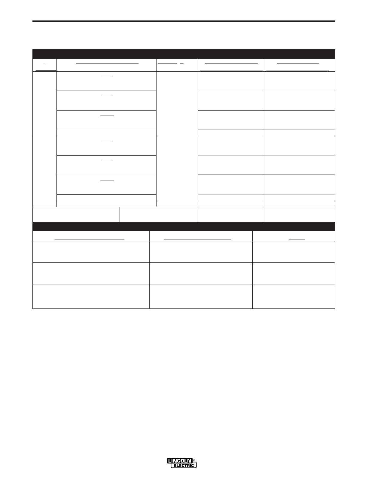
TECHNICAL SPECIFICATIONS-
(K2619-1 Domestic,K2619-2 Canadian-60Hz)
RATED INPUT - SINGLE PHASE ONLY
K
Number
K2618-1
K2619-1
K2619-2
RATED POWER FACTOR (STICK)
Duty Cycle-Applications
40%
AC/DC Stick / Balance TIG
Unbalance (70% Penetration
60%
AC/DC Stick / Balance TIG
Unbalance (70% Penetration
100%
AC/DC Stick / Balance TIG
Unbalance (70% Penetration#) AC TIG
Idle Amps
40%
AC/DC Stick / Balance TIG
Unbalance (70% Penetration#) AC TIG
60%
AC/DC Stick / Balance TIG
Unbalance (70% Penetration
100%
AC/DC Stick / Balance TIG
Unbalance (70% Penetration#) AC TIG
Idle Amps
Idle Power
#
) AC TIG
#
) AC TIG
#
) AC TIG
K2618-1,K2619-1 & K2619-2 .63 min. .85 min.
PRECISION TIG 275 (K2618-1 Domestic Package*-60Hz)
Voltage + 10%
208/230/460
460/575
Max. Amps With Out
Power Factor Capacitor
104/94/47
124/112/56
86/78/39
95/86/43
77/70/35
73/66/33
6/5/3
47/38
56/45
39/31
43/35
35/28
33/26
3/2
300W
Max. Amps With
Power Factor Capacitor
80/72/36
95/86/43
64/58/29
62/56/28
55/50/25
40/36/18
36/32/16
35/28
43/34
29/23
28/23
25/20
18/14
16/13
500W
RATED OUTPUT - NEMA EW1 Class ll (40)
Duty Cycle-Applications
40%
AC/DC Stick / Balance TIG
Unbalance (70% Penetration#) AC TIG
60%
AC/DC Stick / Balance TIG
Unbalance (70% Penetration
#
) AC TIG
100%
AC/DC Stick / Balance TIG
Unbalance (70% Penetration#) AC TIG
*Shown on Front of this IM manual with Under-Cooler Cart and Advanced Control Panel (Refer to Optional Equipment)
#
Exceeds NEMA Unbalanced Load Specification comparable for Auto-Balance.
Volts at Rated Amperes
31.0
16.1
29.0
15.4
28.0
14.8
Amps
275
255
225
200
200
150
PRECISION TIG 275
A-2
Output Current
Range
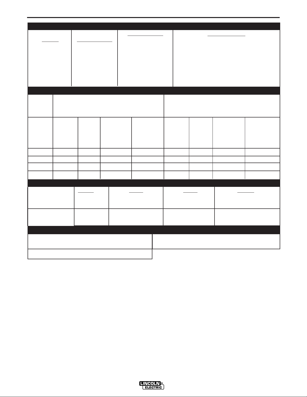
ADDITIONAL OUTPUT CAPACITY
Maximum Open
Circuit Voltage
INSTALLATION
Type of Output
A-2
Auxiliary Power
2Amps DC
to
340Amps AC-DC
For all Stick, DC TIG, and Balanced AC TIG Welding
at 275A/40% Duty Cycle with out Standard Power
Based on the 1999 U.S. National Electrical Code
Input
Voltage /
phase/
Frequency
208/1/60
230/1/60
460/1/60
575/1/60
Fuse
(Super Lag)
or Breaker
Size
125
125
60
50
K2619-1, -2
15Amp Circuit Breaker and NEMA 5-15R Duplex
(STICK AND TIG)
AC/DC OCV: 75/68
*
CC (Constant Current)
AC/DC (GTAW)
Stick (SMAW)
115VAC 8Amp Auxiliary Power Receptacle
115VAC weld Switched Cooler Receptacle load
Receptacle for up to:
RECOMMENDED INPUT WIRE AND FUSE SIZES
For Unbalanced AC TIG Welding Above 275 Amps:
Factor Correction Capacitors
1
Input
Ampere
Rating
Rating on
Nameplate
104
94
47
38
Type 75°C
Copper Wire in
Conduit AWG
(IEC) Sizes
40°C (104°F)
Ambient
4 (21.2 mm2)
4 (21.2 mm2)
8 (8.4mm
10 (5.3mm
Type 75°C
Ground Wire in
Conduit AWG
(IEC) Sizes
6 (13.3 mm2)
6 (13.3 mm2)
2)
10 (5.3mm
2)
10 (5.3mm
Copper
255A/40% Duty Cycle, Auto-Balance Penetration with
out Standard Power Factor Correction Capacitors
Based on the 1999 U.S. National Electrical Code
Type 75°C
Copper Wire in
Conduit AWG
(IEC) Sizes
40°C (104°F)
Ambient
3 (26.7 mm2)
3 (26.7 mm2)
8 (8.4 mm
8 (8.4 mm
2)
2)
2)
2)
Fuse
(Super Lag)
or Breaker
1
Size
150
150
70
60
Input
Ampere
Rating
124
112
56
45
Ground Wire in
PHYSICAL DIMENSIONS
Height Width Depth Weight
31.0 in. 22.0 in. 26.0 in. Approx. 397 lbs.
787 mm 559 mm 660 mm 180 kgs.
Type 75°C
Copper
Conduit AWG
(IEC) Sizes
6 (13.3 mm2)
6 (13.3 mm2)
8 (8.4 mm
10 (5.3mm
2)
2)
K2618-1
49.7 in. 28.0 in. 41.0 in. Approx.641 lbs.
1262 mm 711 mm 1041 mm 291 kgs.
TEMPERATURE RANGES
OPERATING TEMPERATURE RANGE
-20°C to +40°C (-04° to +104°F)
TRANSFORMER INSULATION CLASS 180°C (H)
1
ALSO CALLED ʻINVERSE TIME" OR "THERMAL/MAGNETIC " CIRCUIT BREAKERS; CIRCUIT BREAKERS WHICH HAVE A DELAY IN TRIPPING ACTION THAT DECREASES AS
THE MAGNITUDE OF CURRENT INCREASES.
STORAGE TEMPERATURE RANGE
-40°C to +85°C (-40° to +185°F)
* 50/60HZ IEC Max. range exceeds 310A.
PRECISION TIG 275

A-3
INSTALLATION
A-3
SAFETY PRECAUTIONS
Read entire installation section before starting
installation.
WARNING
ELECTRIC SHOCK can kill.
• Only qualified personnel should
perform this installation.
• Turn the input power OFF at the
disconnect switch or fuse box
before working on this
equipment.
• Do not touch electrically hot
parts.
• Always connect the Precision TIG 275 grounding screw (behind
the reconnect panel cover located near the back of the left case
side) to a good electrical earth ground.
• Always connect the Precision TIG 275 to a power supply
grounded in accordance with the National Electrical Code and
all local codes.
SELECT SUITABLE LOCATION
Place the welder where clean cooling air can freely circulate in through the top rear vents and out through the
bottom rear vents. Dirt, dust or any foreign material
that can be drawn into the welder should be kept at a
minimum. Failure to observe these precautions can
result in excessive operating temperatures and nuisance trips.
ENVIRONMENTAL RATING
Precision TIG 275 power sources carry an IP21S
Environmental rating. They are rated for use in damp,
dirty rain-sheltered environments.
MACHINE GROUNDING AND HIGH FREQUENCY INTERFERENCE PROTECTION
The frame of the welder must be grounded. A ground screw
marked with the symbol is located on the input connection
panel (Figure A.1) for this purpose. See your local and national electrical codes for proper grounding methods.
The spark gap oscillator in the high frequency generator, being similar to a radio transmitter, can be blamed
for many radio, TV and electronic equipment interference problems. These problems may be the result of
radiated interference. Proper grounding methods can
reduce or eliminate radiated interference.
The Precision TIG 275 has been field tested under recommended installation conditions and has been found
to comply with F.C.C. allowable radiation limits. This
welder has also been found to comply with NEMA standards for high frequency stabilized power sources.
Radiated interference can develop in the following four
ways:
GRINDING
Do not direct grinding particles towards the welder. An
abundance of conductive material can cause maintenance problems.
STACKING
The Precision TIG 275's cannot be stacked .
UNDERCARRIAGE LIFTING AND MOVING
When the Precision TIG 275 is purchased as a welding package, or used with any of the available
Undercarriage optional accessories, proper installation
makes the Precision TIG 275 lift bale nonfunctional.
Do not attempt to lift the power source with an undercarriage attached. The undercarriage is designed for
hand moving only; mechanized movement can lead to
personal injury and/or damage to the Precision TIG
275.
TILTING
Each machine must be placed on a secure, level surface, either directly or on a recommended undercarriage. The machine may topple over if this precaution
is not followed.
• Direct interference radiated from the welder.
• Direct interference radiated from the welding leads.
• Direct interference radiated from feedback into the
power lines.
• Interference from re-radiation of "pickup" by
ungrounded metallic objects.
Keeping these contributing factors in mind, installing
the equipment per the following instructions should
minimize problems:
1. Keep the welder power supply lines as short as
possible. Input leads within 50 feet (15.2 m) of the
welder should be enclosed in rigid metallic conduit
or equivalent shielding. There must be good electrical contact between this conduit and the welder.
Both ends of the conduit must be connected to a
driven ground and the entire length must be continuous.
2. Keep the work and electrode leads as short as possible and as close together as possible. Lengths
should not exceed 25 feet (7.6 m). Tape the leads
together when practical.
PRECISION TIG 275

A-4
INSTALLATION
A-4
3. Be sure the torch and work cable rubber coverings
are free of cuts and cracks that allow high frequency leakage. Cables with high natural rubber content,
such as Lincoln Stable-Arc®, better resist high frequency leakage than neoprene and other synthetic
rubber insulated cables.
4. Keep the torch in good repair and all connections
tight to reduce high frequency leakage.
5. The work terminal must be connected to a ground
within ten feet of the welder, using one of the following methods:
• A metal underground water pipe in direct contact
with the earth for ten feet or more.
• A 3/4" (19 mm) galvanized pipe or a 5/8" (16 mm)
solid galvanized iron, steel or copper rod driven at
least eight feet into the ground.
The ground should be securely made and the grounding cable should be as short as possible using cable of
the same size as the work cable, or larger. Grounding
to the building frame electrical conduit or a long pipe
system can result in re-radiation, effectively making
these members radiating antennas. (This is not recommended).
INPUT and GROUNDING CONNECTIONS
WARNING
ELECTRIC SHOCK can kill.
• Turn the input power OFF at the
disconnect switch or fuse box
before working on this
equipment.
Be sure the voltage, phase, and frequency of the input
power is as specified on the rating plate, located on the
rear of the machine.
Fuse the input circuit with the recommended super lag
fuses or delay type1 circuit breakers. Choose an input
and grounding wire size according to local or national
codes or use Section A-2. Using fuses or circuit breakers smaller than recommended may result in "nuisance" tripping from welder inrush currents even if not
welding at high currents.
Unbalanced AC TIG welding draws higher input currents than those for Stick, DC TIG, or Balanced AC TIG
welding. The welder is designed for these higher input
currents. However, where unbalanced AC TIG welding
above 185 amps is planned, the higher input currents
require larger input wire sizes and fuses per Section A-2:
6. Keep all access panels and covers securely in
place.
7. All electrical conductors within 50 feet (15.2 m) of
the welder should be enclosed in grounded rigid
metallic conduit or equivalent shielding. Flexible
helically-wrapped metallic conduit is generally not
suitable.
8. When the welder is enclosed in a metal building,
several good earth driven electrical grounds (as in 5
above) around the periphery of the building are recommended.
Failure to observe these recommended installation
procedures can cause radio or TV interference problems and result in unsatisfactory welding performance
resulting from lost high frequency power.
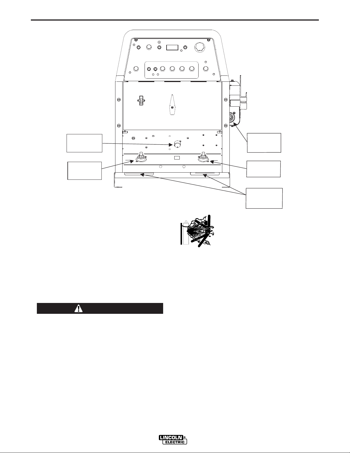
Remove the reconnect panel cover located near the
back of the left case side to reveal the reconnect panel.
Welder supply line entry provision is in the case rear
panel. Entry is through a 1.75 inch (44 mm) diameter
hole in the case back. Appropriate supply line strain
relief clamp is provided by installer. (See Figure A.1)
FIGURE A.1
CONNECT INPUT
POWER LEADS
CONNECT INPUT
GROUND LEAD
CONNECT INPUT
VOLTAGE LEVEL
All connections should be made in accordance
with all local codes and national electrical codes.
Installation by a qualified electrician is recommended.
PRECISION TIG 275

A-5
INSTALLATION
A-5
1. Connect the terminal marked (below the recon-
nect panel) to an earth ground.
2. Connect the input leads to terminals marked L1 (U)
and L2 (V) on the reconnect panel. Use a single
phase line or one phase of a two or three phase line.
3. On multiple input voltage welders, be sure the
reconnect panel is connected for the voltage being
supplied to the welder.
CAUTION
Failure to follow these instructions can cause
immediate failure of components within the welder.
------------------------------------------------------------------------
Welders are shipped connected for the highest input
voltage as listed on the rating plate. To change this
connection, designations on the reconnect panel LOW,
MID, and HIGH correspond to the name plated input
voltages of a triple voltage welder. Dual voltage
welders use only LOW and HIGH.
Recommended Cable Sizes for Combined Lengths of
Copper Work and Electrode Cables using 75
Machine Rating 0 to 100 Ft. 101 to 200 Ft 201 to 250 Ft
275A/40% #1 (42.4 mm2) 1/0 (53.5 mm2) 2/0 (67.4 mm2)
o
C Wire:
WORK CABLE CONNECTION
A 15ʼ (2/0) weld cable with clamp is available (K2150-1), or
included with the Precision TIG Welding Package model.
Otherwise, it is user provided.
With power source off, connect a separate work cable
to the 1/2-13 threaded "WORK" stud of the welder, and
secure a tight connection with the flange nut provided.
The work cable should be routed through the cable
strain relief hole provided in the base directly below the
welding output terminal.
Note: If the Precision TIG is equipped with an UnderCooler or Under-Storage unit, the coiled work cable
and clamp, or excess work cable length, may be conveniently stored in the drawer while remaining connected.
EXAMPLE: On a 208/230/460 volt welder, LOW is
208V, MID is 230V, and HIGH is 460V.
Note: Export model has a voltage range for LOW and
MID connections: LOW is 220-230V, MID is
380-400V and High is 415V.
Reconnect the jumper strap to the terminal stud corresponding to the input voltage level used. Make sure all
connections are tight.
OUTPUT CABLES, CONNECTIONS AND
LIMITATIONS
WARNING
• To avoid being startled by a high frequency
shock, keep the TIG torch and cables in good
condition
• Turn the power switch of the power source OFF
before installing adapters on cable or when connecting or disconnecting adapter plugs to power
source.
-----------------------------------------------------------------------
STICK ELECTRODE CABLE CONNECTION
If manual stick welding is desired, with power source
off, connect a stick electrode cable to the 1/2-13
threaded "STICK Electrode" stud of the welder, and
secure a tight connection with the flange nut provided.
The electrode cable should be routed through the
cable strain relief hole provided in the base directly
below the welding output terminal.
WARNING
DISCONNECT STICK ELECTRODE WELDING
CABLE WHEN TIG WELDING.
EVEN THOUGH HI-FREQ IS NOT APPLIED TO THE
PRECISION TIG STICK TERMINAL, IT WILL BE
ELECTRICALLY "HOT" TO WORK WHEN TIG
WELDING.
------------------------------------------------------------------------
Refer to Figure A.2 for the location of the WORK and
STICK terminals, as well as the TIG Torch connection
panel.
PRECISION TIG 275
A-6
STICK
ELE CTROD E
STUD
TIG TORCH
CONNECT IO
N
PANEL
REMOTE
CONTROL
RECEPTACLE
INSTALLATION
FIGURE A.2
STICK
STICK
WORK
WORK
A-6
WORK
STUD
(Shown without hinged st ud cover)
FIGURE A
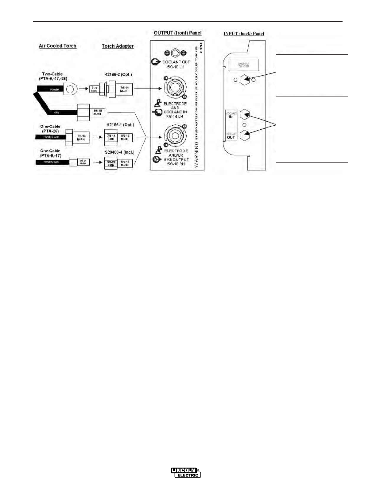
TIG TORCH CONNECTION
The Precision TIG torch connection box, located on the
right side of the machine, provides all the input and
output connections for the installation of both aircooled and water-cooled TIG torches with fittings conforming to Compressed Gas Association (CGA) standards:
Note: The Precision TIG provides an insulated Torch
Reel and Holster for handy and safe storage of connected torch when not welding, and excess torch cable
length while welding.
WARNING
Combination connectors (Power/Water and
Power/Gas) are electrically "hot" while welding in
STICK or TIG modes.
If using an Air-Cooled Torch be sure coolant is
shut off and/or Cooler is unplugged from the
Precision TIG Water Cooler Receptacle on the
torch side of the upper case back.
CABLE
STRAIN
RELI EF HOLE S
CYLINDER could explode
if damaged.
• Keep cylinder upright and
chained to a support.
• Keep cylinder away from areas
where it could be damaged.
• Never allow the torch to touch the cylinder.
• Keep cylinder away from live electrical circuits.
• Maximum inlet pressure 150 psi.
-----------------------------------------------------------------
The Precision TIG machines do not have Hi-Freq.
available at the Stick electrode stud, therefore stud
connection adapters (such as LECO. S19257-series)
cannot be used for torch connection.
Single-piece cable air-cooled torches with a 3/8-24 RH
connector fitting (such as the Magnum PTA-9/-17, or LA9/-17) require the provided S20403-4 Torch Connector,
while those with a 7/8-14 RH connector fitting (such as
the Magnum PTA-26, or LA-26) require the available
K2166-1 Torch Connector. (See Figure A.3)
Observe the safety precautions necessary for handling and using compressed gas containers.
Contact your supplier for specifics.
PRECISION TIG 275
Two-piece cable air-cooled torches (such as PTA-, or LAtorches) can be used with the available 1/2” Stud
Connector (S20403-3) with with a 7/8-14 LH male fitting.
Magnum PTW-18/-20 (or LW-) water-cooled Torches
require no adapter for Precision TIG connection.
A-7
FIGURE A.3
INSTALLATION
A-7
For Gas Supply hose
with 5/8-18RH male
(Provided with Weld
Package model)
For Coolant Supply
Hoses
with 5/8-18LH male
(Provided with Weld
Package model
or
Under-Cooler Cart)
AUXILIARY POWER CONNECTIONS
The Precision TIG machines provide a standard NEMA
5-15R duplex receptacle, located on the upper case
back on the torch side of the machine:
• The bottom outlet of this duplex receptacle provides
switched 115VAC power for the Under-Cooler, or
Water Solenoid accessory. This Cooler receptacle
turns on when the arc starts and remains on for about
8 minutes after the arc goes out (with the Fan-AsNeeded machine cooling fan, see Maintenance
Section), so the Coolerʼs fan and water pump will not
run continuously in idle, but will run while welding.
• The top outlet of this duplex receptacle provides at
least 8 amps at 115VAC, whenever the Precision TIG
Power switch is ON. This auxiliary circuit is intended
for running 115VAC accessories or small power tools.
Note: Some types of equipment, especially pumps
and large motors, have starting currents which are
significantly higher than their running current. These
higher starting currents may cause the circuit breaker
to open. (See next paragraph)
The Precision TIG Export models also provide a
grounded 220vac Euro type Schuko receptacle and a
5 amp circuit breaker, located on the upper case back
on the reconnect side of the machine, intended for use
with a 220vac water cooler.
REMOTE CONTROL (If Used)
The Foot Amptrol (included with the Precision TIG
Welding Package), or other Remote accessory, is
installed by routing the plug of its control cable up
through the left cable strain relief hole provided in the
base (see Figure A.2), then connecting the 6-pin plug
to the mating Remote receptacle behind the stud panel
cover. (See Operation Section B-2 for mating plug
wiring.)
Note: If the Precision TIG is equipped with an UnderCooler or Under-Storage unit, the Foot Pedal (or other
remote control accessory) and coiled control cable, or
excess cable length, may be conveniently stored in the
drawer while remaining connected.
• Both the receptacle circuits are protected from shorts
and overloads by a 15 amp circuit breaker, located
above the receptacle. If the breaker trips, its button
pops out exposing a red ring. When the circuit breaker cools, the button can be reset by pressing it back
in.
Note: When the breaker trips, not only will the auxiliary and cooler power be interrupted, but so will the
power to the shielding gas solenoid and machine
cooling fan.
PRECISION TIG 275
A-8
INSTALLATION
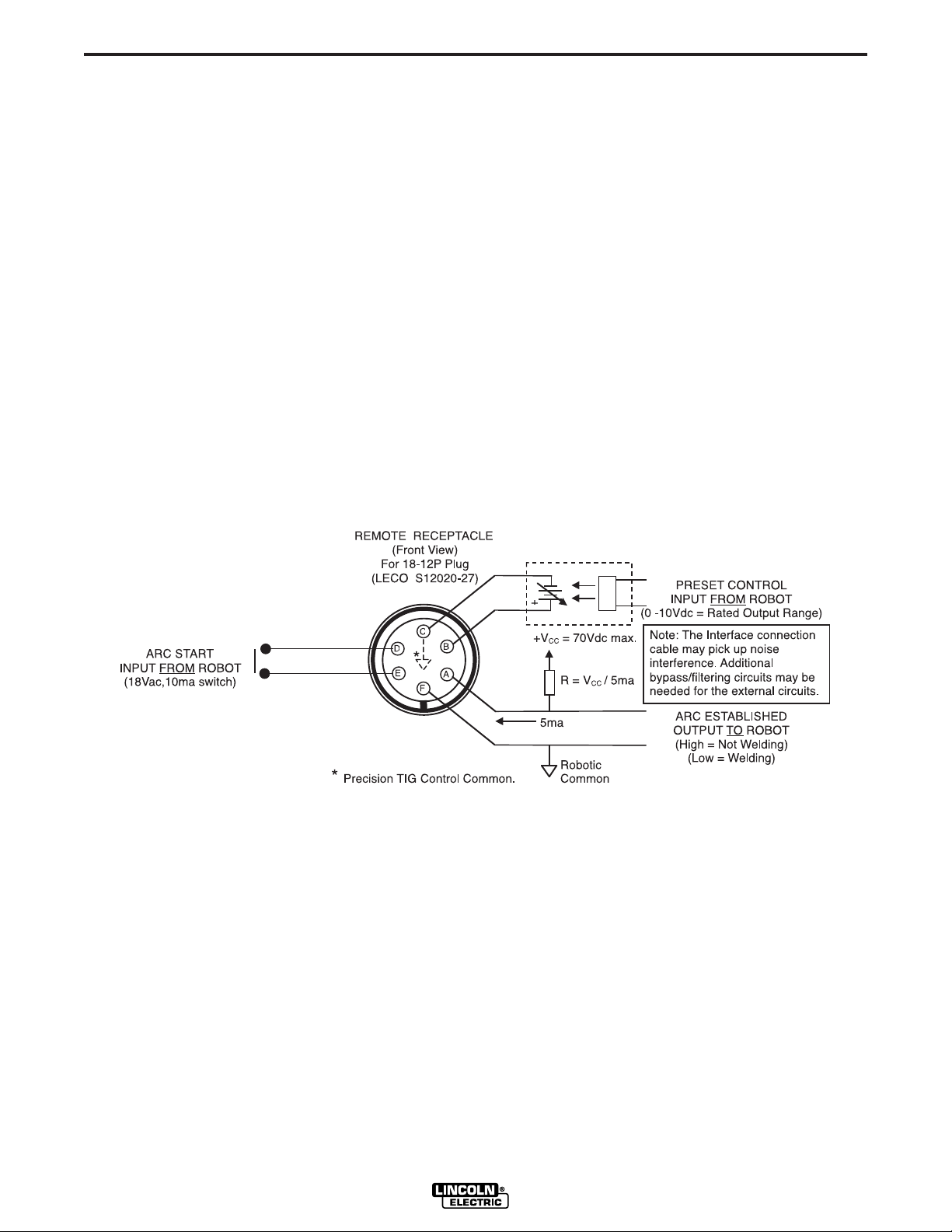
ROBOTIC INTERFACE CONNECTION
Robotic interface can be made at the Remote
Receptacle (See Operation Section B-2). The machine
is shipped with the remote receptacle circuit internally
connected to receptacle J5 of the Control board for
standard Amptrol operation. In order to enable the
remote receptacle for robotic interface its connection
plug must be moved from J5 to J5A on the Control
board. (Refer to the machine Wiring Diagram.)
The robotic interface functions with the Precision TIG
set to either TIG or STICK mode, but must be in
REMOTE switch position for the Preset Control interface to function. When in the REMOTE position with
robotic interface neither the MAXIMUM OUTPUT nor
the MINIMUM OUTPUT panel controls limit the interface control setting over the rated output range of the
machine.
The diagram in Figure A.4 below shows the remote
receptacle plug connections and signals for robotic
interface:
A-8
In addition; a Peak Pulse output signal is provided at
J21 receptacle on the Advanced Control PCB. This
output provides a 0.2A rated switch circuit between pin
1 (+) and pin 2 (com) for an external 40VDC supplied
relay (with coil diode). This switch closes when the
Peak Pulse is on, and opens when off.
FIGURE A.4
PRECISION TIG 275
 Loading...