


Return to Master TOC |
View Safety Info |
Return to Master TOC |
View Safety Info |
Return to Master TOC |
View Safety Info |
Return to Master TOC |
View Safety Info |
RETURN TO MAIN MENU
SVM161-A
February, 2006
INVERTEC V205-T AC/DC
For use with machine code number 10860
Safety Depends on You
Lincoln arc welding and cutting equipment is designed and built with safety in mind. However, your overall safety can be increased by proper installation
. . . and thoughtful operation on your part. DO NOT INSTALL,
OPERATE OR REPAIR THIS EQUIPMENT WITHOUT READING THIS MANUAL AND THE SAFETY PRECAUTIONS CONTAINED THROUGHOUT. And, most importantly, think before you act and be careful.
-T |
AC/DC |
|
 V205
V205
SERVICE MANUAL
Copyright © 2006 Lincoln Global Inc.
•World's Leader in Welding and Cutting Products •
•Sales and Service through Subsidiaries and Distributors Worldwide •
Cleveland, Ohio 44117-1199 U.S.A. TEL: 216.481.8100 FAX: 216.486.1751 WEB SITE: www.lincolnelectric.com

Return to Master TOC
Return to Master TOC
Return to Master TOC
Return to Master TOC
ii |
|
|
|
SAFETY |
|
|
|
|
i |
||
|
|
||
|
|
|
|
|
|
|
|
 WARNING
CALIFORNIA PROPOSITION 65 WARNINGS
Diesel engine exhaust and some of its constituents |
|
The engine exhaust from this product contains |
are known to the State of California to cause can- |
|
chemicals known to the State of California to cause |
cer, birth defects, and other reproductive harm. |
|
cancer, birth defects, or other reproductive harm. |
|
|
|
The Above For Diesel Engines |
|
The Above For Gasoline Engines |
ARC WELDING CAN BE HAZARDOUS. PROTECT YOURSELF AND OTHERS FROM POSSIBLE SERIOUS INJURY OR DEATH. KEEP CHILDREN AWAY. PACEMAKER WEARERS SHOULD CONSULT WITH THEIR DOCTOR BEFORE OPERATING.
Read and understand the following safety highlights. For additional safety information, it is strongly recommended that you purchase a copy of “Safety in Welding & Cutting - ANSI Standard Z49.1” from the American Welding Society, P.O. Box 351040, Miami, Florida 33135 or CSA Standard W117.2-1974. A Free copy of “Arc Welding Safety” booklet E205 is available from the Lincoln Electric Company, 22801 St. Clair Avenue, Cleveland, Ohio 44117-1199.
BE SURE THAT ALL INSTALLATION, OPERATION, MAINTENANCE AND REPAIR PROCEDURES ARE PERFORMED ONLY BY QUALIFIED INDIVIDUALS.
FOR ENGINE powered equipment.
1.a. Turn the engine off before troubleshooting and maintenance work unless the maintenance work requires it to be running.
____________________________________________________
1.b. Operate engines in open, well-ventilated
areas or vent the engine exhaust fumes outdoors.
____________________________________________________
1.c. Do not add the fuel near an open flame welding arc or when the engine is running. Stop the engine and allow it to cool before refueling to prevent spilled fuel from vaporizing on contact with hot engine parts and igniting. Do not spill fuel when filling tank. If fuel is spilled, wipe it up and do not start engine until fumes
have been eliminated.
____________________________________________________
1.d. Keep all equipment safety guards, covers and devices in position and in good repair.Keep hands, hair, clothing and tools away from V-belts, gears, fans and all other moving parts when starting, operating or repairing equipment.
____________________________________________________
1.e. In some cases it may be necessary to remove safety guards to perform required maintenance. Remove guards only when necessary and replace them when the maintenance requiring their removal is complete.
Always use the greatest care when working near moving parts.
___________________________________________________
1.f. Do not put your hands near the engine fan. Do not attempt to override the governor or idler by pushing on the throttle control rods
while the engine is running.
___________________________________________________
1.g. To prevent accidentally starting gasoline engines while turning the engine or welding generator during maintenance work, disconnect the spark plug wires, distributor cap or magneto wire as appropriate.
1.h. To avoid scalding, do not remove the radiator pressure cap when the engine is hot.
ELECTRIC AND MAGNETIC FIELDS may be dangerous
2.a. Electric current flowing through any conductor causes localized Electric and Magnetic Fields (EMF). Welding current creates EMF fields around welding cables and welding machines
2.b. EMF fields may interfere with some pacemakers, and welders having a pacemaker should consult their physician before welding.
2.c. Exposure to EMF fields in welding may have other health effects which are now not known.
2.d. All welders should use the following procedures in order to minimize exposure to EMF fields from the welding circuit:
2.d.1. Route the electrode and work cables together - Secure them with tape when possible.
2.d.2. Never coil the electrode lead around your body.
2.d.3. Do not place your body between the electrode and work cables. If the electrode cable is on your right side, the work cable should also be on your right side.
2.d.4. Connect the work cable to the workpiece as close as possible to the area being welded.
2.d.5. Do not work next to welding power source.
Mar ‘95
V205-T AC/DC

Return to Master TOC
Return to Master TOC
Return to Master TOC
Return to Master TOC
iii |
|
iii |
||
SAFETY |
||||
|
|
|
||
ELECTRIC SHOCK can kill.
3.a. |
The |
electrode |
and |
work |
(or |
ground) |
circuits |
|
|
are |
electrically |
“hot” |
when |
the |
welder |
is |
on. |
|
Do not touch these “hot” parts |
with your |
bare |
|||||
|
skin or wet clothing. Wear |
dry, |
hole-free |
|||||
|
gloves to insulate hands. |
|
|
|
|
|||
3.b. Insulate yourself from work and ground using dry insulation. Make certain the insulation is large enough to cover your full area of physical contact with work and ground.
In addition to the normal safety precautions, if welding must be performed under electrically hazardous conditions (in damp locations or while wearing wet clothing; on metal structures such as floors, gratings or scaffolds; when in cramped positions such as sitting, kneeling or lying, if there is a high risk of unavoidable or accidental contact with the workpiece or ground) use the following equipment:
•Semiautomatic DC Constant Voltage (Wire) Welder.
•DC Manual (Stick) Welder.
•AC Welder with Reduced Voltage Control.
3.c. In semiautomatic or automatic wire welding, the electrode, electrode reel, welding head, nozzle or semiautomatic welding gun are also electrically “hot”.
3.d. Always be sure the work cable makes a good electrical connection with the metal being welded. The connection should be as close as possible to the area being welded.
3.e. Ground the work or metal to be welded to a good electrical (earth) ground.
3.f. Maintain the electrode holder, work clamp, welding cable and welding machine in good, safe operating condition. Replace damaged insulation.
3.g. Never dip the electrode in water for cooling.
3.h. Never simultaneously touch electrically “hot” parts of electrode holders connected to two welders because voltage between the two can be the total of the open circuit voltage of both welders.
3.i. When working above floor level, use a safety belt to protect yourself from a fall should you get a shock.
3.j. Also see Items 6.c. and 8.
ARC RAYS can burn.
4.a. Use a shield with the proper filter and cover plates to protect your eyes from sparks and the rays of the arc when welding or observing open arc welding. Headshield and filter lens should conform to ANSI Z87. I standards.
4.b. Use suitable clothing made from durable flame-resistant material to protect your skin and that of your helpers from the arc rays.
4.c. Protect other nearby personnel with suitable, non-flammable screening and/or warn them not to watch the arc nor expose themselves to the arc rays or to hot spatter or metal.
FUMES AND GASES
can be dangerous.
5.a. Welding may produce fumes and gases
hazardous to health. Avoid breathing these fumes and gases.When welding, keep your head out of the fume. Use enough ventilation and/or exhaust at the arc to keep
fumes and gases away from the breathing zone. When welding with electrodes which require special ventilation such as stainless or hard facing (see instructions on container or MSDS) or on lead or cadmium plated steel and other metals or coatings which produce highly toxic fumes, keep exposure as low as possible and below Threshold Limit Values (TLV) using local exhaust or mechanical ventilation. In confined spaces or in some circumstances, outdoors, a respirator may be required. Additional precautions are also required when welding on galvanized steel.
5.b. Do not weld in locations near chlorinated hydrocarbon vapors coming from degreasing, cleaning or spraying operations.The heat and rays of the arc can react with solvent vapors to form phosgene, a highly toxic gas, and other irritating products.
5.c. Shielding gases used for arc welding can displace air and cause injury or death. Always use enough ventilation, especially in confined areas, to insure breathing air is safe.
5.d. Read and understand the manufacturer’s instructions for this equipment and the consumables to be used, including the material safety data sheet (MSDS) and follow your employer’s safety practices. MSDS forms are available from your welding distributor or from the manufacturer.
5.e. Also see item 1.b.
Mar ‘95
V205-T AC/DC

Return to Master TOC
Return to Master TOC
Return to Master TOC
Return to Master TOC
iv |
iv |
|
|
|
SAFETY |
WELDING SPARKS can cause fire or explosion.
6.a. Remove |
fire |
hazards from the welding area. |
||||
If this |
is |
not |
possible, cover them to prevent |
|||
the |
welding |
sparks from |
starting |
a |
fire. |
|
Remember |
that welding |
sparks |
and |
hot |
||
materials from welding can easily go through small cracks and openings to adjacent areas. Avoid welding near hydraulic lines. Have a fire extinguisher readily available.
6.b. Where compressed gases are to be used at the job site, special precautions should be used to prevent hazardous situations. Refer to “Safety in Welding and Cutting” (ANSI Standard Z49.1) and the operating information for the equipment being used.
6.c. When not welding, make certain no part of the electrode circuit is touching the work or ground. Accidental contact can cause overheating and create a fire hazard.
6.d. Do not heat, cut or weld tanks, drums or containers until the proper steps have been taken to insure that such procedures will not cause flammable or toxic vapors from substances inside. They can cause an explosion even though they have been “cleaned”. For information, purchase “Recommended Safe Practices for the Preparation for Welding and Cutting of
Containers and Piping That Have Held Hazardous Substances”, AWS F4.1 from the American Welding Society
(see address above).
6.e. Vent hollow castings or containers before heating, cutting or welding. They may explode.
6.f. Sparks and spatter are thrown from the welding arc. Wear oil free protective garments such as leather gloves, heavy shirt, cuffless trousers, high shoes and a cap over your hair. Wear ear plugs when welding out of position or in confined places. Always wear safety glasses with side shields when in a welding area.
6.g. Connect the work cable to the work as close to the welding area as practical. Work cables connected to the building framework or other locations away from the welding area increase the possibility of the welding current passing through lifting chains, crane cables or other alternate circuits. This can create fire hazards or overheat lifting chains or cables until they fail.
6.h. Also see item 1.c.
CYLINDER may explode


 if damaged.
7.a. Use only compressed gas cylinders
containing the correct shielding gas for the process used and properly operating regulators designed for the gas and
pressure used. All hoses, fittings, etc. should be suitable for the application and maintained in good condition.
7.b. Always keep cylinders in an upright position securely chained to an undercarriage or fixed support.
7.c. Cylinders should be located:
•Away from areas where they may be struck or subjected to physical damage.
•A safe distance from arc welding or cutting operations and any other source of heat, sparks, or flame.
7.d. Never allow the electrode, electrode holder or any other electrically “hot” parts to touch a cylinder.
7.e. Keep your head and face away from the cylinder valve outlet when opening the cylinder valve.
7.f. Valve protection caps should always be in place and hand tight except when the cylinder is in use or connected for use.
7.g. Read and follow the instructions on compressed gas cylinders, associated equipment, and CGA publication P-l,
“Precautions for Safe Handling of Compressed Gases in Cylinders,” available from the Compressed Gas Association 1235 Jefferson Davis Highway, Arlington, VA 22202.
FOR ELECTRICALLY powered equipment.
8.a. Turn off input power using the disconnect switch at the fuse box before working on the equipment.
8.b. Install equipment in accordance with the U.S. National Electrical Code, all local codes and the manufacturer’s recommendations.
8.c. Ground the equipment in accordance with the U.S. National Electrical Code and the manufacturer’s recommendations.
Mar ‘95
V205-T AC/DC

Return to Master TOC
Return to Master TOC
Return to Master TOC
Return to Master TOC
v |
SAFETY |
v |
|
|
|
|
|
PRÉCAUTIONS DE SÛRETÉ
Pour votre propre protection lire et observer toutes les instructions et les précautions de sûreté specifiques qui parraissent dans ce manuel aussi bien que les précautions de sûreté générales suivantes:
Sûreté Pour Soudage A L’Arc
1.Protegez-vous contre la secousse électrique:
a.Les circuits à l’électrode et à la piéce sont sous tension quand la machine à souder est en marche. Eviter toujours tout contact entre les parties sous tension et la peau nue ou les vétements mouillés. Porter des gants secs et sans trous pour isoler les mains.
b.Faire trés attention de bien s’isoler de la masse quand on soude dans des endroits humides, ou sur un plancher metallique ou des grilles metalliques, principalement dans
les positions assis ou couché pour lesquelles une grande partie du corps peut être en contact avec la masse.
c.Maintenir le porte-électrode, la pince de masse, le câble de
soudage et la machine à souder en bon et sûr état defonctionnement.
d.Ne jamais plonger le porte-électrode dans l’eau pour le refroidir.
e.Ne jamais toucher simultanément les parties sous tension des porte-électrodes connectés à deux machines à souder parce que la tension entre les deux pinces peut être le total de la tension à vide des deux machines.
f.Si on utilise la machine à souder comme une source de courant pour soudage semi-automatique, ces precautions pour le porte-électrode s’applicuent aussi au pistolet de soudage.
2.Dans le cas de travail au dessus du niveau du sol, se protéger contre les chutes dans le cas ou on recoit un choc. Ne jamais enrouler le câble-électrode autour de n’importe quelle partie du corps.
3.Un coup d’arc peut être plus sévère qu’un coup de soliel, donc:
a.Utiliser un bon masque avec un verre filtrant approprié ainsi qu’un verre blanc afin de se protéger les yeux du rayonnement de l’arc et des projections quand on soude ou quand on regarde l’arc.
b.Porter des vêtements convenables afin de protéger la peau de soudeur et des aides contre le rayonnement de l‘arc.
c.Protéger l’autre personnel travaillant à proximité au soudage à l’aide d’écrans appropriés et non-inflammables.
4.Des gouttes de laitier en fusion sont émises de l’arc de soudage. Se protéger avec des vêtements de protection libres de l’huile, tels que les gants en cuir, chemise épaisse, pantalons sans revers, et chaussures montantes.
5.Toujours porter des lunettes de sécurité dans la zone de soudage. Utiliser des lunettes avec écrans lateraux dans les zones où l’on pique le laitier.
6.Eloigner les matériaux inflammables ou les recouvrir afin de prévenir tout risque d’incendie dû aux étincelles.
7.Quand on ne soude pas, poser la pince à une endroit isolé de la masse. Un court-circuit accidental peut provoquer un
échauffement et un risque d’incendie.
8.S’assurer que la masse est connectée le plus prés possible de la zone de travail qu’il est pratique de le faire. Si on place la masse sur la charpente de la construction ou d’autres endroits
éloignés de la zone de travail, on augmente le risque de voir passer le courant de soudage par les chaines de levage, câbles de grue, ou autres circuits. Cela peut provoquer des risques d’incendie ou d’echauffement des chaines et des câbles jusqu’à ce qu’ils se rompent.
9.Assurer une ventilation suffisante dans la zone de soudage. Ceci est particuliérement important pour le soudage de tôles galvanisées plombées, ou cadmiées ou tout autre métal qui produit des fumeés toxiques.
10.Ne pas souder en présence de vapeurs de chlore provenant d’opérations de dégraissage, nettoyage ou pistolage. La chaleur ou les rayons de l’arc peuvent réagir avec les vapeurs du solvant pour produire du phosgéne (gas fortement toxique) ou autres produits irritants.
11.Pour obtenir de plus amples renseignements sur la sûreté, voir le code “Code for safety in welding and cutting” CSA Standard W 117.2-1974.
PRÉCAUTIONS DE SÛRETÉ POUR LES MACHINES À SOUDER À TRANSFORMATEUR ET À REDRESSEUR
1.Relier à la terre le chassis du poste conformement au code de l’électricité et aux recommendations du fabricant. Le dispositif de montage ou la piece à souder doit être branché à une bonne mise à la terre.
2.Autant que possible, I’installation et l’entretien du poste seront effectués par un électricien qualifié.
3.Avant de faires des travaux à l’interieur de poste, la debrancher à l’interrupteur à la boite de fusibles.
4.Garder tous les couvercles et dispositifs de sûreté à leur place.
V205-T AC/DC

vi |
vi |
MASTER TABLE OF CONTENTS FOR ALL SECTIONS
|
|
RETURN TO MAIN MENU |
|
|
|
|
Page |
Safety................................................................................................................................................. |
|
i-iv |
|
|
|
|
|
Installation ............................................................................................................................. |
|
Section A |
|
|
|
|
|
Operation............................................................................................................................... |
|
Section B |
|
|
|
|
|
Accessories........................................................................................................................... |
|
Section C |
|
|
|
|
|
Maintenance ......................................................................................................................... |
|
Section D |
|
|
|
|
|
Theory of Operation ............................................................................................................. |
|
Section E |
|
|
|
|
|
Troubleshooting and Repair................................................................................................. |
|
Section F |
|
Safety Precautions ...................................................................................................................... |
|
F-2 |
|
How to Use Troubleshooting Guide |
............................................................................................ |
F-2 |
|
Troubleshooting Guide ................................................................................................................ |
|
F-4 |
|
Test Procedures .......................................................................................................................... |
|
F-9 |
|
Replacement Procedures ......................................................................................................... |
|
F-49 |
|
|
|
|
|
Electrical Diagrams.............................................................................................................. |
|
Section G |
|
|
|
|
|
Parts Manual ..................................................................................................................... |
|
P400 Series |
|
V205-T AC/DC

Return to Master TOC
Return to Master TOC
Return to Master TOC
Return to Master TOC
A-1 A-1
TABLE OF CONTENTS
- INSTALLATION SECTION -
INSTALLATION ...................................................................................................................... |
Section A |
Technical Specifications ............................................................................................................. |
A-2 |
Select Suitable Location ............................................................................................................. |
A-3 |
Machine Grounding/High Frequency Interference Protection.................................................... |
A-3 |
Reconnect Procedures ............................................................................................................... |
A-4 |
Output Connections.................................................................................................................... |
A-6 |
V205-T AC/DC

Return to Section TOC |
Return to Master TOC |
Return to Section TOC |
Return to Master TOC |
Return to Section TOC |
Return to Master TOC |
Return to Section TOC |
Return to Master TOC |
A-2 |
|
|
|
|
|
|
INSTALLATION |
|
|
|
|
|
A-2 |
|
|||||||
|
|
|
|
|
|
|
|
|
|
|
|
|
|
|
|
|
|||||
TECHNICAL SPECIFICATIONS - V205-T AC/DC TIG K1855-1 (Code Number 10860) |
|
||||||||||||||||||||
|
|
|
|
|
|
|
|
|
|
|
|
|
|
|
|
|
|
||||
|
|
|
|
|
|
|
INPUT - SINGLE PHASE ONLY |
|
|
|
|||||||||||
|
|
|
|
|
|
|
|
|
|
|
|
|
|
|
|
||||||
|
|
Input Voltages / 50 /60 Hz. |
|
|
|
|
|
|
|
Max. Input Current |
|
|
|
||||||||
|
|
|
115 |
|
|
|
|
|
|
|
|
34A at Rated Output |
|
|
|
||||||
|
|
|
230 |
|
|
|
|
|
|
|
|
30A at Rated Output |
|
|
|
||||||
|
|
|
|
|
|
|
|
|
|
|
|
|
|
|
|
|
|
|
|
|
|
|
|
|
|
|
|
|
|
|
|
|
|
|
|
|
|
|
|
|
|
|
|
|
|
|
|
|
|
|
|
|
|
RATED OUTPUT |
|
|
|
|
|
|
|
|
|||
|
|
Duty Cycle |
|
|
|
|
|
|
|
|
|
|
|
|
|
|
|
|
|||
|
|
|
Input Amps |
|
|||||||||||||||||
|
|
|
|
|
Output Amps |
Volts at Rated Amperes |
|
|
|
|
|||||||||||
|
|
(115V) |
35% |
|
|
|
|
|
(Stick) 110 |
|
24.4V |
|
|
|
|
|
34A |
|
|
||
|
|
|
60% |
|
|
|
|
|
90 |
|
23.6V |
|
|
|
|
|
28A |
|
|
||
|
|
|
100% |
|
|
|
|
|
70 |
|
22.8V |
|
|
|
|
|
20A |
|
|
||
|
|
|
|
|
|
|
|
|
|
|
|
|
|
|
|
|
|
|
|
|
|
|
|
(115V) |
40% |
|
|
|
|
|
(TIG) 150 |
|
16V |
|
|
|
|
|
34A |
|
|
||
|
|
|
60% |
|
|
|
|
|
120 |
|
14.8V |
|
|
|
|
|
25A |
|
|
||
|
|
|
100% |
|
|
|
|
|
100 |
|
14V |
|
|
|
|
|
20A |
|
|
||
|
|
|
|
|
|
|
|
|
|
|
|
|
|
|
|
|
|
|
|
|
|
|
|
(230V) |
35% |
|
|
|
|
|
(Stick) 180 |
|
27.2V |
|
|
|
|
|
30A |
|
|
||
|
|
|
60% |
|
|
|
|
|
150 |
|
26V |
|
|
|
|
|
23A |
|
|
||
|
|
|
100% |
|
|
|
|
|
130 |
|
25.2V |
|
|
|
|
|
19A |
|
|
||
|
|
|
|
|
|
|
|
|
|
|
|
|
|
|
|
|
|
|
|
|
|
|
|
(230V) |
40% |
|
|
|
|
|
(TIG) 200 |
|
18V |
|
|
|
|
|
30A |
|
|
||
|
|
|
60% |
|
|
|
|
|
170 |
|
16V |
|
|
|
|
|
18A |
|
|
||
|
|
|
100% |
|
|
|
|
|
140 |
|
15.6V |
|
|
|
|
|
15A |
|
|
||
|
|
|
|
|
|
|
|
|
|
|
|
|
|
|
|
|
|
|
|
|
|
|
|
|
|
|
|
|
|
|
|
OUTPUT |
|
|
|
|
|
|
|
|
|||
|
|
Output Current |
|
|
|
|
|
Maximum Open |
|
|
|
|
|
Type of Output |
|
|
|||||
|
|
Range |
|
|
|
|
|
Circuit Voltage |
|
|
|
|
|
|
|
|
|||||
|
|
6-200 Amps |
|
|
|
|
|
54 Volts Max. |
|
|
|
|
|
AC/DC |
|
|
|||||
|
|
|
|
|
|
|
|
|
|
|
|
|
|
|
|
|
|
||||
|
|
|
|
|
|
|
|
|
|
|
|
|
|
|
|
|
|
|
|
|
|
|
|
RECOMMENDED INPUT WIRE AND FUSE SIZES FOR MAXIMUM RATED OUTPUT |
|
||||||||||||||||||
|
|
|
|
|
|
|
|
|
|
|
|
|
|
|
|
|
|
|
|
||
|
|
INPUT |
|
TYPE S, SO ST, STO, OR EXTRA |
|
TIME-DELAY CIRCUIT BREAKER |
|
||||||||||||||
|
|
VOLTAGE / |
|
HARD USAGE INPUT CORD AWG |
|
OR FUSE SIZE (AMPS) |
|
||||||||||||||
|
|
FREQUENCY |
|
|
|
|
|
|
|
|
|
|
|
|
|
|
|
|
|
|
|
|
|
(HZ) |
|
|
|
|
|
|
|
|
|
|
|
|
|
|
|
|
|
|
|
|
|
|
|
|
|
|
|
|
|
|
|
|
|
|
|
|
|
|
|
||
|
115/50/60 |
|
#12 |
|
|
|
|
|
|
|
|
30A |
|
||||||||
|
230/50/60 |
|
|
|
|
|
|
|
|
|
|
||||||||||
|
|
|
|
|
|
|
|
|
|
|
|
|
|
|
|
|
|
|
|||
|
|
|
|
|
|
|
|
|
|
|
|
|
|
|
|
|
|
|
|
|
|
|
|
|
|
|
|
|
|
PHYSICAL DIMENSIONS |
|
|
|
|
|
|
|
|
|
||||
|
|
|
|
|
|
|
|
|
|
|
|
|
|
|
|
|
|
|
|
|
|
|
Height |
Width |
|
|
|
|
|
Depth |
|
Weight |
|
|
|
||||||||
|
15 in. |
8.5 in. |
|
|
|
|
|
19 in. |
|
Approx. 38 lbs. |
|
|
|
||||||||
|
381 mm |
216 mm |
|
|
|
|
|
483 mm |
|
17 kgs. |
|
|
|
||||||||
|
|
|
|
|
|
|
|
|
|
|
|
|
|
|
|
|
|
|
|
|
|
TEMPERATURE RANGES
OPERATING TEMPERATURE RANGE |
STORAGE TEMPERATURE RANGE |
-20°C to +40°C |
-50°C to +85°C |
|
|
V205-T AC/DC

Return to Section TOC |
Return to Master TOC |
Return to Section TOC |
Return to Master TOC |
Return to Section TOC |
Return to Master TOC |
Return to Section TOC |
Return to Master TOC |
A-3 |
INSTALLATION |
A-3 |
|
|
Read entire installation section before starting installation.
Safety Precautions
 WARNING
ELECTRIC SHOCK can kill.
•Only qualified personnel should perform this installation.
•Turn the input power OFF and unplug the machine from the receptacle before working on this equipment. Allow machine to sit for 5 minutes minimum to allow the power capacitors to discharge before working inside this equipment.
•Insulate yourself from the work and ground.
•Always wear dry insulating gloves.
•Always connect the V205-T to a power supply grounded according to the National Electrical Code and local codes.
------------------------------------------------------------
SELECT SUITABLE LOCATION
The Invertec will operate in harsh environments. Even so, it is important that simple preventative measures are followed in order to assure long life and reliable operation.
•The machine must be located where there is free circulation of clean air such that air movement in the back and out the front will not be restricted.
•Dirt and dust that can be drawn into the machine should be kept to a minimum. Failure to observe these precautions can result in excessive operating temperatures and nuisance shutdown.
STACKING
The Invertec V205-T AC/DC can not be stacked.
TILTING
Place the machine directly on a secure, level surface. The machine may topple over if this procedure is not followed.
ENVIRONMENTAL AREA
Keep the machine dry. Do not place it on wet ground or in puddles.
MACHINE GROUNDING AND HIGH FREQUENCY INTERFERENCE PROTECTION
The Capacitor Discharge Circuit used in the high frequency generator, may cause many radio, TV and electronic equipment interference problems. These problems may be the result of radiated interference. Proper grounding methods can reduce or eliminate radiated interference.
The Invertec V205-T AC/DC has been field tested under recommended installation conditions. It complies with FCC allowable limits for radiation.
Radiated interference can develop in the following four ways:
1.Direct interference radiated from the welder.
2.Direct interference radiated from the welding leads.
3.Direct interference radiated from feedback into the power lines.
4.Interference from re-radiation of “pickup” by ungrounded metallic objects.
Keeping these contributing factors in mind, installing equipment per the following instructions should minimize problems.
1.Keep the welder power supply lines as short as possible and enclose as much of them as possible in rigid metallic conduit or equivalent shielding for a distance of 50 feet (15.2m). There should be good electrical contact between this conduit and the welder case ground. Both ends of the conduit should be connected to a driven ground and the entire length should be continuous.
2.Keep the work and electrode leads as short as possible and as close together as possible. Lengths should not exceed 25 ft (7.6m). Tape the electrode and work leads together into one bundle when practical.
V205-T AC/DC

Return to Section TOC |
Return to Master TOC |
Return to Section TOC |
Return to Master TOC |
Return to Section TOC |
Return to Master TOC |
Return to Section TOC |
Return to Master TOC |
A-4 |
A-4 |
|
|
INSTALLATION |
|
|
3. Be sure the torch and work cable rubber coverings |
INPUT CONNECTIONS |
|
are free of cuts and cracks that allow high fre- |
|
|
quency leakage. Cables with high natural rubber |
Be sure the voltage, phase, and frequency of the input |
|
content, such as Lincoln Stable-Arc® better resist |
power is as specified on the rating plate, located on the |
|
high frequency leakage than neoprene and other |
bottom of the machine. |
|
synthetic rubber insulated cables. |
|
4.Keep the torch in good repair and all connections tight to reduce high frequency leakage.
5.The work terminal must be connected to a ground within ten feet of the welder, using one of the following methods.
a)A metal underground water pipe in direct contact with the earth for ten feet or more.
b)A 3/4” (19mm) galvanized pipe or a 5/8” (16mm) solid galvanized iron, steel or copper rod driven at least eight feet into the ground.
The ground should be securely made and the grounding cable should be as short as possible using cable of the same size as the work cable, or larger. Grounding to the building frame electrical conduit or a long pipe system can result in re-radi- ation, effectively making these members radiating antennas.
6.Keep all panels securely in place.
7.All electrical conductors within 50 ft (15.2m) of the welder should be enclosed in grounded, rigid metallic conduit or equivalent shielding. Flexible metallic conduit is generally not suitable.
8.When the welder is enclosed in a metal building, several earth driven electrical grounds connected (as in 5b above) around the periphery of the building are recommended.
Failure to observe these recommended installation procedures can cause radio or TV interference problems.
 WARNING
ELECTRIC SHOCK can kill.
• Have a qualified electrician install and service this equipment.
•Turn the input power OFF and unplug the machine from the receptacle
before working on this equipment.
•Allow machine to sit for 5 minutes minimum to allow the power capacitors to discharge before working inside this equipment.
•Do not touch electrically hot parts.
•Machine must be plugged into a receptacle that is grounded according to the National Electrical Code and local codes.
•Do not remove or defeat the purpose of the power cord ground pin.
-----------------------------------------------------------------------
RECONNECT PROCEDURE
The Invertec V205-T AC/DC auto reconnects to either 115V or 230V supply.
Fuse the input circuit with time delay fuses or delay type1 circuit breakers. Using fuses or circuit breakers smaller than recommended may result in “nuisance” shut-offs from welder inrush currents even if not welding at high currents.
The Invertec V205-T AC/DC is recommended for use on an individual branch circuit.
1Also called “inverse time” or “thermal/magnetic” circuit breakers. These circuit breakers have a delay in tripping action that decreases as the magnitude of the current increases.
V205-T AC/DC
Return to Section TOC |
Return to Master TOC |
Return to Section TOC |
Return to Master TOC |
Return to Section TOC |
Return to Master TOC |
Return to Section TOC |
Return to Master TOC |
A-5 |
INSTALLATION |
A-5 |
|
|
230V INPUT
The equipment is provided with a 230/115V cable, 6.6ft.(2m) in length with a 230V 6-50P attachment plug.
The Invertec V205-T AC/DC performs best when connected to 230VAC inputs. This input allows full output of the machine (200 amps).
115V INPUT
A suitable 115V attachment plug must be installed on the power cord to use the V205-T AC/DC with a 115V input supply. The rated output of the V205-T AC/DC is available when connected to a 30A branch circuit. When connected to a branch circuit with lower amp rating, lower welding current and duty cycle must be used. An output guide is provided below. The values are approximate and must be adjusted downward if the fuse or circuit breaker trips off. Other loads on the circuit and fuse/circuit breaker characteristics will affect the available output. Do not exceed these welding conditions:
15A branch circuit
10% duty cycle Stick: 75A TIG: 105A
20A branch circuit
10% duty cycle Stick: 90A TIG: 130A
ATTACHMENT PLUG INSTALLATION
Connect the white (neutral) wire under terminal clamp with silver screw, and black (hot) wire under terminal clamp with brass screw. Connect green wire under terminal clamp with green screw.
 WARNING
Failure to wire as instructed may cause personal injury or damage to equipment. To be installed or checked by an electrician or qualified person only.
---------------------------------------------------------------------------
In all cases, the green or green/yellow grounding wire must be connected to the grounding pin of the plug, usually identified by a green screw.
Attachment plugs must comply with the Standard for Attachment Plugs and Receptacles, UL498.
The product is considered acceptable for use only when an attachment plug as specified is properly attached to the supply cord.
For use on engine drives, keep in mind the above input draw restrictions and the following precaution.
ENGINE DRIVEN GENERATOR
The Invertec V205-T AC/DC can be operated on engine driven generators as long as the 230 volt auxiliary meets the following conditions:
•The AC waveform peak voltage is below 400 volts.
•The AC waveform frequency is between 45 and 65Hz.
The following Lincoln engine drives meet these conditions when run in the high idle mode:
•Ranger 250,305
•Commander 300, 400, & 500
Some engine drives do not meet these conditions (e.g. Miller Bobcats, etc). Operation of the Invertec V205-T AC/DC is not recommended on engine drives not conforming to these conditions. Such drives may deliver unacceptably high voltage levels to the Invertec V205- T AC/DC power source.
V205-T AC/DC

Return to Section TOC |
Return to Master TOC |
Return to Section TOC |
Return to Master TOC |
Return to Section TOC |
Return to Master TOC |
Return to Section TOC |
Return to Master TOC |
A-6 |
INSTALLATION |
A-6 |
|
|
OUTPUT CONNECTIONS
 WARNING
ELECTRIC SHOCK can kill.
•Keep the electrode holder, TIG torch and cable insulation in good condition and in place.
•Do not touch electrically live parts or electrode with skin or wet clothing.
•Insulate yourself from work and ground.
•Turn the input line Switch on the Invertec V205- T AC/DC “off” before connecting or disconnecting output cables or other equipment.
This unit does not include a TIG torch, but one may be purchased separately. The accessories section of this manual lists a number of Lincoln Electric TIG torches, and TIG Torch Starter Packs that are recommended for use with this machine; however, any similar TIG torch can be used. To attach the Twist-Mate Plug to a Lincoln Torch, slide the rubber boot onto the torch cable (enlarge the boot opening if necessary), screw the fitting on the torch cable into the brass connector snugly and slide the boot back over the brass connector.
OUTPUT CONNECTION FOR STICK
TIG ADAPTER |
|
|
|
|
|
|
|
|
STRAIN RELIEF BOOT |
||||||||||||||||||
|
|
|
|
|
|
|
|
|
|
|
|
|
|
|
|
|
|
|
|
|
|
|
|
|
|
|
|
|
|
|
|
|
|
|
|
|
|
|
|
|
|
|
|
|
|
|
|
|
|
|
|
|
|
|
|
|
|
|
|
|
|
|
|
|
|
|
|
|
|
|
|
|
|
|
|
|
|
|
|
|
|
|
|
|
|
|
|
|
|
|
|
|
|
|
|
|
|
|
|
|
|
|
|
|
|
|
|
|
|
|
|
|
|
|
|
|
|
|
|
|
|
|
|
|
|
|
|
|
|
|
|
|
|
|
|
|
|
|
|
RETAINING COMPOUND |
TIG TORCH POWER CABLE WITH GAS FITING |
-----------------------------------------------------------
OUTPUT AND GAS CONNECTION FOR TIG WELDING (FIGURE A.1)
The TIG Torch Twist-Mate and work cable Twist-Mate Connectors are supplied with the welder. To connect the cables, turn the Power Switch “OFF”. Connect the torch cable Twist-Mate plug into the DC(-) Electrode/Gas Output Receptacle on the front of the welder and turn it clockwise until snug,(Do not Overtighten). This is a quick connect terminal and also provides the gas connection for the shielding gas to the torch.
WELDING (FIGURE A.2)
First determine the proper electrode polarity for the electrode to be used. Consult the electrode data for this information. Then connect the output cables to the output terminals corresponding to this polarity. For instance, for DC(+) welding, connect the electrode cable (which is connected to the electrode holder) to the “+” output terminal and the work cable (which is connected to the work clamp) to the “-” output terminal. Insert the connector with the key lining up with the keyway, and rotate clockwise; until the connection is snug. Do not over tighten.
 WARNING
To avoid receiving a high frequency shock, keep the TIG torch and cable insulation in good condition.
___________________________________________
WORK CABLE CONNECTION
Next, connect the work cable to the “+” output terminal in the same way. To minimize high frequency interference, refer to Machine Grounding and High Frequency Interference Protection section of this manual for the proper procedure on grounding the work clamp and work piece.
FIGURE A.2
WORK CABLE
WORK CABLE |
- |
+
STICK ELECTRODE
HOLDER
FIGURE A.1
TIG TORCH
-
+
WORK CABLE |
WORK CLAMP |
|
V205-T AC/DC
Return to Section TOC |
Return to Master TOC |
Return to Section TOC |
Return to Master TOC |
Return to Section TOC |
Return to Master TOC |
Return to Section TOC |
Return to Master TOC |
A-7 |
INSTALLATION |
A-7 |
|
|
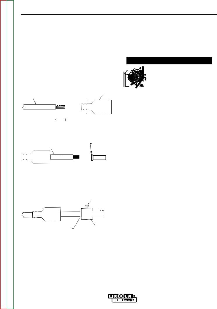
QUICK DISCONNECT PLUG (FOR STICK ELECTRODE CABLE and WORK CABLE)
A quick disconnect system is used for the welding cable connections. The stick electrode cable will need to have a plug attached.
1.Cut off welding cable lug, if present.
2.Remove 1.00 in. (25mm) of welding cable insulation.
3.Slide rubber boot onto cable end. The boot end may be trimmed to match the cable diameter. Use soap or other nonpetroleum-based lubricant to help slide the boot over the cable, if needed.
BOOT
WELDING CABLE
 1.00 in.
25 mm |
TRIM, IF REQ’D |
TO FIT OVER CABLE |
4. Insert copper strands into ferrule.
COPPER FERRULE
WELDING CABLE
5.Slide the copper ferrule into the brass plug.
6.Tighten set screw to collapse copper tube. Screw must apply pressure against welding cable. The top of the set screw will be well below the surface of the brass plug after tightening.
SET SCREW
SHIELDING GAS CONNECTION
Obtain the necessary inert shielding gas. Connect the cylinder of gas with a pressure regulator and flow gage. Install a gas hose between the regulator and gas inlet (located on the rear of the welder). The gas inlet has a 5/16-18 right hand female thread; CGA #032.
 WARNING
CYLINDER could explode if damaged.
• Keep cylinder upright and chained to a support.
•Keep cylinder away from areas where it could be damaged.
•Never allow the torch or welding electrode to touch the cylinder.
•Keep cylinder away from live electrical cir-
cuits.
___________________________________________
REMOTE CONTROL CONNECTION
A remote control receptacle is provided on the lower center case front of the welder for connecting a remote control to the machine. Refer to the Optional Accessories section of this manual for available remote controls.
BRASS PLUG
COPPER TUBE
7.Slide rubber boot over brass plug. The rubber boot must be positioned to completely cover all electrical surfaces after the plug is locked into the receptacle.
V205-T AC/DC

A-8
Return to Section TOC |
Return to Master TOC |
Return to Section TOC |
Return to Master TOC |
Return to Section TOC |
Return to Master TOC |
Return to Section TOC |
Return to Master TOC |
A-8
NOTES
V205-T AC/DC

Return to Master TOC
Return to Master TOC
Return to Master TOC
Return to Master TOC
B-1 B-1
TABLE OF CONTENTS |
|
- OPERATION SECTION - |
|
Operation............................................................................................................................... |
Section B |
Safety Instructions ...................................................................................................................... |
B-2 |
General Description .................................................................................................................... |
B-2 |
Welding Capability ...................................................................................................................... |
B-2 |
Limitations................................................................................................................................... |
B-2 |
Rear Control Panel...................................................................................................................... |
B-3 |
Controls and Settings ................................................................................................................. |
B-4 |
Set Up Menu............................................................................................................................... |
B-7 |
Output Limitations ...................................................................................................................... |
B-8 |
DC TIG Welding .......................................................................................................................... |
B-8 |
Welding Polarity .......................................................................................................................... |
B-8 |
Steel TIG Welding ..................................................................................................................... |
B-10 |
Copper TIG Welding ................................................................................................................. |
B-10 |
Tips for AC TIG Welding ........................................................................................................... |
B-10 |
AC TIG Welding Quick Start Up ............................................................................................... |
B-11 |
DC TIG Welding Quick Start Up ............................................................................................... |
B-12 |
V205-T AC/DC
Return to Section TOC |
Return to Master TOC |
Return to Section TOC |
Return to Master TOC |
Return to Section TOC |
Return to Master TOC |
Return to Section TOC |
Return to Master TOC |
B-2 |
OPERATION |
B-2 |
|
|
|
|
|
Read and understand this entire section before operating your machine.
SAFETY INSTRUCTIONS
 WARNING
GENERAL DESCRIPTION
The Invertec V205-T AC/DC is an industrial 200 amp arc welding power source which utilizes single phase input power, to produce constant current output. The welding response of this Invertec has been optimized for stick (SMAW) and TIG (GTAW). The unit is ideal for industrial applications where portability is important.
The Invertec V205-T AC/DC is a power source that can
ELECTRIC SHOCK can kill. perform the following types of welding with excellent results:
•Do not touch electrically live parts
such as output terminals, electrode or TIG (with high frequency or Touch Start Tig Starting).
internal wiring.
•Insulate yourself from the work and ground.
•Always wear dry insulating gloves.
____________________________________
FUMES AND GASES can be dangerous.
• Keep your head out of fumes.
•Use ventilation or exhaust to remove fumes from breathing zone.
____________________________________
WELDING, CUTTING and GOUGING SPARKS
can cause fire or explosion
•Keep flammable material away.
•Do not weld, cut or gouge on containers that have held com-
bustibles.
____________________________________
•TIG AC with square, sinusoidal and triangular waveforms
•Tig DC
The following items can be connected to the 6 pin socket on the front panel:
•Remote control potentiometer for Stick welding.
•Remote Foot Amptrol or Hand Amptrol
•Arc Start Switch
NOTE: See Accessories section of this manual for product numbers and complete description.
WELDING CAPABILITY
The Invertec V205-T AC/DC is rated at 200 amps, 18 volts, at 40% duty cycle on a ten minute basis. It is capable of higher duty cycles at lower output currents. It is capable of 140 amps, 15.6 volts at at 100% duty cycle. If the duty cycle is exceeded, a thermal protector will shut off the output until the machine cools. See Technical Specifications in A-1 for other rated outputs.
The Invertec V205-T is recommended for stick welding with such popular electrodes as Fleetweld 35, Fleetweld 37, Fleetweld 180 and Excalibur 7018.
LIMITATIONS
The V205-T is not recommended for pipe thawing.
ARC RAYS can burn.
•Wear eye, ear and body protection.
____________________________________
Only qualified personnel should operate this equipment. Observe all safety information throughout this manual.
V205-T AC/DC

B-3
Return to Section TOC |
Return to Master TOC |
Return to Section TOC |
Return to Master TOC |
Return to Section TOC |
Return to Master TOC |
Return to Section TOC |
Return to Master TOC |
B-3
OPERATION
REAR CONTROL PANEL (FIGURE B.1)
 WARNING
• I1: Off/On switch turns on the electric power to the welder. It has two positions, "O" off, and "I" on.
------------------------------------------------------------------------
*With "l1" in the "I" (ON) position, the welding machine is operational and there is voltage between the positive (+) and negative (-) Terminals in stick welding. In TIG, the welding process needs a trigger closure command at the remote control connection.(Usually via an Arc Start Switch or Foot Amptrol)
*The welder is connected to the supply even if the “l1” (Power Switch) is in the "O" (Off) position, and therefore there are electrically live parts inside the power source. Carefully follow the instructions given in this manual.
FIGURE B.1
*1 : Supply cable
*2 : Gas attachment
l1 : Power Switch
V205-T AC/DC
Return to Section TOC |
Return to Master TOC |
Return to Section TOC |
Return to Master TOC |
Return to Section TOC |
Return to Master TOC |
Return to Section TOC |
Return to Master TOC |
B-4 |
OPERATION |
B-4 |
|
|
|
|
|
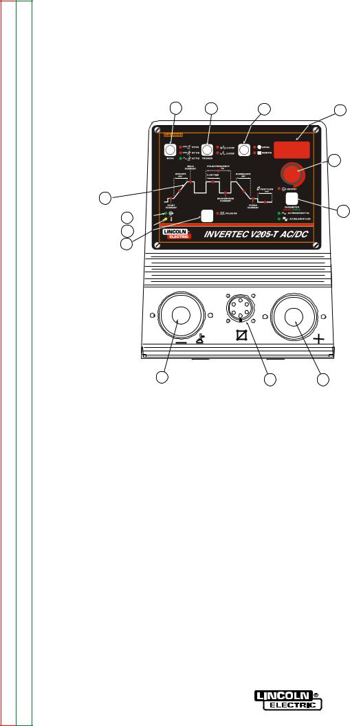
CONTROLS AND SETTINGS
All operator controls and adjustments are located on the case front of the V205-T machine. Refer to Figure
B.2 and the corresponding explanations.
FIGURE B.2
9 8 7
LOCAL
sec
sec
13
1 
2 
3
10 |
11 |
|
1.Input Voltage warning light green LED - Indicates that the machine is on and input voltage is within acceptable range.
2.Thermal Shutdown Light (yellow LED) - Indicates thermal over load or output disabled for incorrect supply voltage.
•With the "Yellow LED" on, and an alarm code blinking on "Digital Display Item 6" (see Troubleshooting Section E, "Possible electrical problems"), the machine will not supply power at the output.
•If over-heating occurs, the "Yellow LED" will stay on until the machine has sufficiently cooled. Leave the power source on to allow the fan to cool the unit.
3.Pulse On/OFF push button - CONSTANT current - PULSED current
6
1. Input Voltage warning Light Green LED
2. Thermal / Device Warning Light Yellow LED
3. Pulse On/Off Button
4. Setup/Parameter Select Button
5 5. Output/Parameter Adjust Knob
6. Digital Display
7. Local/Remote Button
8.Trigger Selection Button
9. Welding Process (MODE) Button
410. Electrode Connection (Negative)
11.Remote Control Connector
12.Electrode Connection (Positive)
13. Welding Parameter Drawing
12
4.Setup/Parameter Select push button -
“Setup/Parameter" push button has three (3) different functions:
•Accesses Welding Parameter. Repeatedly pressing the Parameter button will step through the Welding Parameter waveform lights on the front panel. Parameters which can be changed.
Start Current
Upslope
Weld Current (Peak Current) Pulse Frequency
% on Time Background Current Downslope
Finish Current Postflow sec.
There is a LED for each welding parameter. When lit, it has confirmed the mode or selection chosen.
•Accesses the "AC Frequency" and "AC Balance" by pressing and holding the Parameter button for three (3) seconds.
•Accesses the "Set Up Menu". See Set Up Menu section.
V205-T AC/DC

Return to Section TOC |
Return to Master TOC |
Return to Section TOC |
Return to Master TOC |
Return to Section TOC |
Return to Master TOC |
Return to Section TOC |
Return to Master TOC |
B-5 |
OPERATION |
B-5 |
||
5. Output / Parameter Adjust Knob- Allows you to |
|
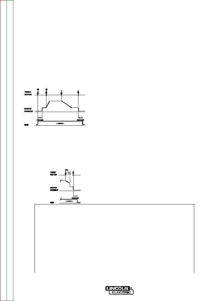
2 STEP DIAGRAM 1 |
||
|
|
|||
continuously adjust the current both in TIG and in Stick |
|
(1) |
||
welding. Allows you to change the value, shown on |
|
|
||
"Digital Display Item 6", of the parameter selected with |
|
|
||
"Setup/Parameter select button Item 4". |
|
|
|
|
6. Digital Display - displays currently set values for |
|
|
||
each mode or welding parameter. |
|
|
|
|
7. Local/Remote push button - Selects the welding |
|
|
||
current adjusting system: |
|
Possible variations of this standard sequence is shown |
||
• from front panel |
|
in (2 step diagram 2). It is possible to press and hold |
||
• from remote control |
|
the TIG torch trigger a second time during downslope |
||
The LED beside the symbol confirms the selection. |
to restart. After the trigger is pressed the output current |
|||
|
|
will increase to the welding current. This operation is |
||
8. Tig Trigger Sequences - |
|
shown in (2 step diagram 2). |
||
For the V205-T AC/DC, TIG welding can be done in |
|
2 STEP DIAGRAM 2 |
||
either the 2-step or 4-step mode which is selected with |
|
|||
(1) |
(2) |
|||
the Trigger Mode Push Button. |
|
|||
|
|
|
||
2-Step Sequence |
|
|
|
|
With the Trigger Mode switch in the 2-step position, |
|
|
||
the following welding sequence will occur. This |
|
|
||
sequence is shown in (2-step diagram 1) |
|
|
|
|
1. Press and hold the Arc Start Switch to start the |
4-Step Sequence |
sequence. |
With the 4-step Selected, the following welding |
|
sequence will occur. |
The machine will open the gas valve to start the flow |
|
of the shielding gas. After a 0.5 second preflow time, |
1. Press and hold the Arc Start Switch to start the |
to purge air from the torch hose, the output of the |
sequence. |
machine is turned ON. At this time the arc is started. |
|
|
The machine will open the gas valve to start the flow |
After the arc is started the output current will be |
of the shielding gas. After a 0.5 second preflow time, |
increased from the start current to the welding cur- |
to purge air from the torch hose, the output of the |
rent. Both the start current and increase, or upslope |
machine is turned ON. At this time the arc is started. |
time are presettable. The default start current is 15 |
|
amps and the default upslope time is 0.2 seconds. |
After the arc is started the output current will be at |
|
the Start current. This condition can be maintained |
2. Release the Arc Start Switch to stop welding. |
as long or as short as necessary. |
The machine will now decrease the output current at |
|
a controlled rate, or downslope time, until the Finish |
If the Start current is not necessary, do not hold the |
current, (also commonly referred to as Crater |
TIG torch trigger as described at the beginning of this |
Current) is reached and the output of the machine is |
step. Instead, quickly press and release the trigger. |
turned OFF. Both the Downslope Time and the Finish |
In this condition, the machine will automatically pass |
Current are can be preset. |
from Step 1 to Step 2 when the arc is started. |
After the arc is turned OFF, the gas valve will remain |
2. Release the TIG torch trigger to start the main part |
open to continue the flow of the shielding gas to the |
of the weld. |
hot electrode and work piece. The duration of this |
|
postflow shielding gas is adjusted by the Postflow |
The output current will be increased from the start |
Parameter. |
current to the welding current. Both the start current |
|
and increase, or upslope time are presettable. The |
|
default start current is 15 amps and the default ups- |
|
lope time is 0.2 seconds. |
V205-T AC/DC
Return to Section TOC |
Return to Master TOC |
Return to Section TOC |
Return to Master TOC |
Return to Section TOC |
Return to Master TOC |
Return to Section TOC |
Return to Master TOC |
B-6 |
OPERATION |
B-6 |
|
|
|
|
|
3.Press and hold the TIG torch trigger when the main part of the weld is complete.
The machine will now decrease the output current at a controlled rate, or downslope time, until the Finish current is reached. Both the Downslope Time and the Finish Current are presettable. This Finish current can be maintained as long or as short as necessary.
4.Release the TIG torch trigger.
The output current of the machine will turn OFF and the gas valve will remain open to continue the flow of the shielding gas. The duration of this postflow time is adjusted by the Postflow parameter. This operation is shown in (4 step diagram 1).
4 STEP DIAGRAM 1
(3)(4)
Possible variations of this standard sequence are shown below.
By releasing and re-pressing the TIG torch trigger during the downslope step, the output will immediately drop to and hold at the Finish Current. Releasing the trigger will turn off the output and begin postflow. This operation shown in (4 step diagram 2)
4 STEP DIAGRAM 2
9.Welding selection button - Permits selection of the welding mode. The LED beside the symbol confirm the selection:
•Stick
•TIG DC
•TIG AC
10.Electrode Connection (Negative) - For quick disconnect system using Twist-MateTM cable plugs with gas pass through for TIG Torches.
11.Remote Control Connector - For the connection of a Lincoln Foot Amptrol, Hand Amptrol or Arc Start Switch. See the ACCESSORIES section for available options.
12.Electrode Connection (Positive) - For quick disconnect system using Twist-MateTM cable plugs
13.Welding Parameter Display - LED’s show which mode or welding parameter is activated for adjustment.
•If it is necessary to modify the welding parameters "Item 13":
-Wait four seconds after the LED’s on the panel have gone out, the welding current LED will be lit.
-Press the SETUP/Parameter push button "Item 4"; every time the push button is pressed, one of the LED’s in the diagram “Item 13” comes on (in clockwise sequence) and the value of the parameter appears on the Digital display "Item 6". Stop at the desired parameter.
-Rotate the Output/Parameter Adjust Knob"Item 5" and modify the parameter value.
-Press the SETUP/Parameter "Item 4" push button again to pass to another parameter, or wait five seconds and the Weld Current LED will come on again.
WELDING PARAMETER DEFAULTS AND RANGES
|
PARAMETER |
VALUE |
MIN |
MAX |
DEFAULT |
|
|
START CURRENT |
AMPS |
6 |
MAX |
15 |
|
|
UPSLOPE |
SEC. |
0 |
10 |
0.2 |
|
|
WELD CURRENT* |
AMPS |
6 |
MAX |
100 |
|
|
DOWNSLOPE |
SEC. |
0 |
10 |
1.0 |
|
|
FINISH CURRENT |
AMPS |
6 |
MAX |
8 |
|
|
POSTFLOW |
SEC. |
0.2 |
60 |
5.0 |
|
|
PULSE FREQUENCY |
HZ |
0.1 |
500 |
0.5 |
|
|
% ON TIME |
% |
5 |
95 |
50 |
|
|
BACKGROUND CURRENT |
% OF WELD CURRENT |
1 |
100 |
20 |
|
|
AC FREQUENCY |
HZ |
20 |
150 |
100 |
|
|
AC BALANCE |
% EN |
35 |
85 |
65 |
|
|
|
(EN = Electrode Negative) |
|
|
|
|
|
MODE |
|
|
|
DC TIG |
|
|
TRIGGER |
|
|
|
2 STEP |
|
|
LOCAL / REMOTE |
|
|
|
LOCAL |
|
|
|
|
|
|
|
|
* Maximum Weld Current can be limited by input voltage, Welding Mode, AC TIG waveform and AC TIG frequency.
V205-T AC/DC
Return to Section TOC |
Return to Master TOC |
Return to Section TOC |
Return to Master TOC |
Return to Section TOC |
Return to Master TOC |
Return to Section TOC |
Return to Master TOC |
B-7 |
OPERATION |
B-7 |
|
|
SET UP MENU
Many additional parameters can be modified via the Set Up Menu. To access the Set Up Menu:
•Position the ON/OFF switch to OFF “0”.
•Depress and hold the Parameter select Push Button.
•Position the On/Off switch to on "I" at the back of the machine; the input voltage light "Item 1" (green LED) confirms normal operation.
•The SETUP mode is confirmed by a center "0" on the Digital display “Item 6”.
-Rotate the Output / Parameter Adjust Knob, the Digital Display shows the numbers corresponding to the parameters in sequence; stop at the desired parameter and push the "Setup/Parameter Push Button".
-The number on the Digital display "Item 6" is replaced by the value of the parameter that can be modified through the Output / Parameter adjust knob "Item 5".
-With parameter (9) all the modifications made in the SETUP mode are cancelled and the standard values set by Invertec V205-T AC/DC are restored.
-To exit the Set Up Menu, return to “0” and press the Setup/Parameter Push Button
INDICATOR |
PARAMETER |
|
DEFAULT |
||||
|
|
|
|
|
|||
0 |
Exit From Set Up |
|
|
|
|||
1 |
Not Used |
|
|
|
|||
2 |
Pre Flow Time (0 - 25 seconds) |
|
0.5 sec. |
||||
3 |
Arc Force, percent above Peak Current for Stick only (0 - 100%) |
|
30% |
|
|||
4 |
Hot Start, percent above Peak Current for Stick only (0 - 100%) |
|
80% |
|
|||
5 |
Setting of AC wave Form |
|
2 (Square) |
||||
|
0 = Sinusoidal |
|
|
|
|||
|
1 = Triangular |
|
|
|
|||
|
2 = Square |
|
|
|
|||
|
NOTE: This parameter limits maximum weld current, see "OUTPUT LIMITATIONS" section of the manual. |
|
|
|
|||
6 |
Min. Weld Current Value with Remote Control,for TIG only. |
|
10 Amps |
||||
|
(6 Amps - Value set for Indicator 7) |
|
|
|
|||
7 |
Max. Weld Current Value with Remote Control,for TIG only. |
|
Peak Current |
||||
|
(Value set for Indicator 6 - Peak Current) |
|
|
|
|||
|
NOTE: Peak Current (Max Weld Current) can be limited by input voltage, welding mode, AC TIG waveform and AC TIG frequency. |
|
|
|
|||
8 |
Touch Start or H.F. Start in DC TIG (0 = H.F. Start, 1 = touch Start) |
|
0 |
|
|||
|
This parameter is ignored in AC TIG Mode |
|
|
|
|||
9 |
Reset all Parameters, (including control panel settings) |
|
|
|
|||
10 |
Not Used |
|
|
|
|||
11 |
Not Used |
|
|
|
|||
12 |
2 Step Trigger Selection |
|
1 |
|
|||
|
0 = Restart Disabled |
|
|
|
|||
|
1 = Restart Enabled |
|
|
|
|||
13 |
4 Step Trigger Selection |
|
0 |
|
|||
|
0 = Restart Disabled |
|
|
|
|||
|
1 = Restart Enabled |
|
|
|
|||
14 |
Start Power , for TIG only |
|
2.0 |
|
|||
|
This function sets the initial start energy limit. |
|
|
|
|||
|
(1.0 = min., 5.0 = max.) |
|
|
|
|||
|
Note: If the machine does not initiate a welding arc it will repeat the |
|
|
|
|||
|
starting sequence with an increased start energy up to this limit. |
|
|
|
|||
|
Set this number to a higher setting than the factory default if |
|
|
|
|||
|
needed to improve starting of large diameter tungstens electrodes. |
|
|
|
|||
|
|
|
|
|
|||
|
V205-T AC/DC |
|
|
||||
|
|
|
|
|
|
|
|
|
|
|
|
|
|
|
|
|
|
|
|
|
|
|
|
|
|
|
|
|
|
|
|

Return to Section TOC |
Return to Master TOC |
Return to Section TOC |
Return to Master TOC |
Return to Section TOC |
Return to Master TOC |
Return to Section TOC |
Return to Master TOC |
B-8 |
OPERATION |
B-8 |
|
|
OUTPUT LIMITATIONS
The maximum output current as specified in the installation section of this manual is derated in two situations; alternate AC Wave Forms and elevated AC Frequencies.
• Alternate AC Wave Forms (See Set Up Menu)
Square |
200 amps max. output |
Sinusoidal |
150 amps max. output |
Triangular |
120 amps max output |
• Elevated AC Frequencies
Above 85Hz (AC output) the square wave output is limited to 170 amps. Elevated AC Frequencies do not effect the output of Sinusoidal and Triangular Waveforms.
These derated values have been programmed into the Invertec V205-T AC/DC to ensure reliable operation.
DC TIG WELDING
(see FIGURE B.3)
The TIG (Tungsten lnert Gas) welding process is based on the presence of an electric arc between a non-consumable electrode (pure or alloyed tungsten with an approximate melting temperature of 3370°C) and the workpiece. An inert gas (typically argon) atmosphere protects the weld pool.
To avoid inclusions of tungsten in the joint, the electrode should not contact the workpiece. For this reason the arc is started through a Hi. Freq. generator.
For situations requiring no Hi. Freq., Touch Start Tig reduces the short-circuit current to keep tungsten inclusions to the minimum.
To improve weld bead quality at the end of the weld it is important to carefully control the downslope of current and ensure proper gas coverage over the weld.
WELDING POLARITY
DC Electrode Negative Polarity (Direct Current Straight Polarity)
(see FIGURE B.4)
While Welding, there is a continuous flow of electrons from the electrode to the workpiece.
This is the most used polarity, ensuring limited wear of the electrode, since the majority of the heat concentrates on the anode (workpiece). Narrow and deep welds are obtained with high travel speeds.
Most materials, with the exception of aluminum and magnesium, are welded with this polarity.
FIGURE B.4
FIGURE B.3
1) |
Workpiece |
5) |
Flowmeter |
2) |
Filler material |
6) |
Pressure reducer |
3) |
Non-consumable electrode 7) |
lnert gas (typically argon) |
|
4) |
Torch |
8) |
Power source |
V205-T AC/DC

Return to Section TOC |
Return to Master TOC |
Return to Section TOC |
Return to Master TOC |
Return to Section TOC |
Return to Master TOC |
Return to Section TOC |
Return to Master TOC |
B-9 |
B-9 |
OPERATION
DC Electrode Positive Polarity. (Direct Current Reverse Polarity) (see Figure B.5)
In this case, there is a continuous flow of electrons from the workpiece to the electrode. The reverse polarity is used for welding alloys covered with a layer of refractory oxide.
With this polarity the electrode functions as anode and is subjected to a high degree of heat; the workpiece is bombardment by positive ions sent from the electrode which break the surface oxide.
In Electrode Positive Polarity, high currents cannot be used, since they would cause an excessive wear of the electrode.
NOTE: (The Invertec V205-T AC/DC cannot be used for Electrode Positive TIG welding without special adapters.)
FIGURE B.5
D.C.-Pulsed TIG
(see Figure B-6)
The use of pulsed direct current allows better control of the weld pool during certain operating conditions.
When compared with traditional TIG welding performed at the same average current, pulsed welding results in a smaller heat affected zone which results in fewer deformations and reduced chance of cracking and gas entrapment.
Increasing the frequency constricts the arc, increases stability and improves weld quality.
FIGURE B.6
A.C. (Alternating Current)
(see Figure B.7)
Alternating Current welding is typically used for Tig welding aluminum (and its alloys) or magnesium. The polarity alternates between Electrode Positive and Electrode Negative (EN). During the positive half-wave the oxide is broken. During the negative half-wave, the electrode cools, the workpiece melts and penetration occurs.
FIGURE B.7
Greater % EN = MORE PENETRATION |
|
50% (EN) |
|
Lesser % EN = more CLEANING |
|
|
|
|
|
|
|
|
|
|
|
|
|
|
|
Changing the wave balance alters the ratio between the cleaning and the penetrating current.
A.C.-Pulsed TIG
When AC welding, a pulsed current can be used, with similar effects to those described in pulsed direct current welding.
FIGURE B.8
A.C.- PULSED TIG
DC TIGNOT PULSED
DC-PULSED TIG
V205-T AC/DC

Return to Section TOC |
Return to Master TOC |
Return to Section TOC |
Return to Master TOC |
Return to Section TOC |
Return to Master TOC |
Return to Section TOC |
Return to Master TOC |
B-10 |
B-10 |
OPERATION
STEEL TIG WELDING
The TIG process is very effective for welding both carbon steel and alloy steel, especially in applications requiring precision results. DC Electrode Negative Polarity is required. Since this process does not include the removal of impurities, proper cleaning and preparation of the edges is required.
FILLER MATERIAL:
The filler rods must deposit welds with mechanical characteristics appropriate for the application.
COPPER TIG WELDING
Since the TIG welding is a process characterized by high heat concentration, it is particularly suitable for welding materials with high thermal conductivity, like copper. As with steel, the DC Electrode Negative Polarity is employed, with argon as protective gas.
Considering the fluidity of molten copper, the use of backup support may prove useful.
FILLER MATERIAL:
In order to avoid the oxidation of the molten material, filler materials containing phosphorus, silicon or other deoxidating materials are typically used. The mechanical properties can also be improved through the use of silver.
TIPS FOR AC TIG WELDING
AC Inverter TIG power sources offer two significant advantages over conventional Silicon Controlled Rectifier (SCR) / transformer power sources:
1.The AC wave balance can be set to a higher percentage electrode negative which minimizes tungsten heating and erosion.
2.The AC frequency can be varied to "focus" the arc. Increasing the AC frequency above 60Hz will narrow the cone shape arc from the tungsten’s tip. Decreasing the AC frequency below 60Hz will broaden the cone shape arc from the tungsten’s tip.
The two above benefits can be used to maintain a tight focus of the arc for precise heat control and tight joint access. Because of the AC inverters abilities in these areas the following recommendations are made as a starting point:
•A 2% Thoriated tungsten is recommended instead of the Pure tungsten that is normally recommended for AC welding. Thoriated tungstens emit electrons easier and therefore will improve starting.
•Sharpen the tungsten to a point. Normally it is recommended to pre-ball a pure tungsten when AC welding with a conventional power source. However, the AC inverter with it’s extended AC balance control minimized tungsten heating thus allowing for a pointed tungsten to be used.
•Set the AC Balance control to maximum 85% electrode negative. This can be reduced if the material welded is heavily oxidized, however starting at maximum and adjusting to less is desired.
•Set the AC Frequency in the 100 to 120 Hz range. This is a "Sweet Spot" for most aluminum applications.
GTAW Process
Electrode Polarity |
DC- |
AC |
|
Approximate Argon |
|
|||
Electrode Tip Preparation |
Sharpened |
Sharpened |
|
Gas Flow Rate |
|
|||
|
|
|
|
|
|
C.F.H. (l/min.) |
|
|
Electrode Type |
|
|
|
|||||
|
|
|
|
|
|
|||
|
|
|
EWTh-2, EWLa-1 |
EWTh-2, EWLa-1 |
|
|
Stainless |
|
|
|
|
|
|
||||
Electrode Size-in. (mm) |
|
|
|
|
Aluminum |
Steel |
||
.010 |
(0.25) |
|
Up to 15 A. |
Up to 15 A. |
|
3-8 (2-4) |
3-8 |
(2-4) |
.020 |
(0.50) |
|
Up to 15 A. |
Up to 20 A. |
|
5-10 (3-5) |
5-10 |
(3-5) |
.040 |
(1.0) |
|
Up to 80 A. |
Up to 60 A. |
|
5-10 (3-5) |
5-10 |
(3-5) |
1/16 |
(1.6) |
|
Up to 150 A. |
Up to 130 A. |
|
5-10 (3-5) |
9-13 (4-6) |
|
3/32 |
(2.4) |
|
Up to MAX. A. |
Up to MAX. A. |
|
13-17 (6-8) |
11-15 (5-7) |
|
1/8 |
(3.2) |
|
X |
X |
|
15-23 (7-11) |
11-15 |
(5-7) |
Tungsten electrodes are classified as follows by the American Welding Society (AWS): |
|
|
|
|
||||
+2% Thoria .......................EWTh-2...red |
|
|
|
|
|
|||
+1.5% Lanthana ...............EWLa-1 ...black |
|
|
|
|
|
|||
V205-T AC/DC

Return to Section TOC |
Return to Master TOC |
Return to Section TOC |
Return to Master TOC |
Return to Section TOC |
Return to Master TOC |
Return to Section TOC |
Return to Master TOC |
B-11 |
OPERATION |
B-11 |
|
|
|
|
|
PROTECTIVE GAS
Both argon and helium work when welding aluminum. Argon is preferred, due to its lower cost and consumption rate. This gas also tends to stabilize the arc, thus making it easy to operate. For some applications, however, the use of helium, or argon-helium blends, is recommended due to better weld penetration and faster travel speed. Helium is especially suitable for welding thick workpieces. The recommended gas flow rates are shown in table 5.
|
TABLE 5 |
|
|
|
|
Current (A) |
|
Helium cfh-(l/min) |
50 |
|
29 - (14) |
100 |
|
29 - (14) |
150 |
|
42 - (20) |
200 |
|
42 - (20) |
250 |
|
53 - (25) |
300 |
|
53 - (25) |
|
|
|
AC TIG WELDING QUICK START UP
The Invertec V205 T AC/DC TIG is ready to AC TIG weld with the following features:
•AC TIG
•Trigger Mode in 2 step mode
•Local control
•Pulser off
•AC Square Wave
•AC Balance 65% EN
•AC Frequency 100HZ
•Pre Flow .5sec.
•Post Flow 5 sec.
•High Freq Start
Change from Local to Remote control by pushing front panel push button.
Set the maximum output current desired using the Output Control. Initiate the arc by closing the arc start switch. The Amptrol will control the output current from 10 amps to current level set by Output Control.
WARNING |
To change the AC Frequency, press and hold the |
|
Parameter button for 3 seconds. The AC Frequency is now selected and can be varied by the Output Control.
ELECTRIC SHOCK can kill. The frequency is displayed on the digital meter. After
•Have an electrician install and about 5 seconds, the power source will switch back to service this equipment. the welding mode ready to weld with the new selected
•Turn the input power off at the fuse box, disconnect or unplug supply lines and allow machine to sit for five minutes minimum to allow the power capacitors to discharge before working inside this equipment.
•Do not touch electrically hot parts.
------------------------------------------------------------------------
Connect the shielding gas – typically argon – using a appropriate regulator. Connect the foot amptrol, torch and work lead to the power source.
With the work cable connected to a properly grounded work piece, turn the power source on.
AC Frequency.
To change the AC Balance, press and hold the Parameter button for 3 seconds, AC Frequency is selected, press the Parameter button again and AC Balance is selected. Adjust the Output Control for the desired AC Balance. After about 5 seconds, the power source will switch back to the welding mode ready to weld with the new selected AC Balance.
To change the Post Flow time, repeatedly push the Parameter button until the Post Flow indicator light is on. Adjust the Output control to the desired Post Flow time as indicated on digital display.
V205-T AC/DC

Return to Section TOC |
Return to Master TOC |
Return to Section TOC |
Return to Master TOC |
Return to Section TOC |
Return to Master TOC |
Return to Section TOC |
Return to Master TOC |
B-12 |
OPERATION |
B-12 |
|
|
|
|
|
DC TIG WELDING QUICK START UP
 WARNING
ELECTRIC SHOCK can kill.
•Have an electrician install and service this equipment.
•Turn the input power off at the fuse box, disconnect or unplug supply lines and allow machine to sit for five minutes minimum to allow the power capacitors to discharge before working inside this equipment.
•Do not touch electrically hot parts.
------------------------------------------------------------------------
Connect up the shielding gas – typically argon – using an appropriate regulator. Connect foot amptrol, torch and work lead to power source.
With the Work cable connected to a properly grounded work piece, turn the power source on.
To change to DC TIG Welding:
•Press Mode button to select "DC TIG."
•Press Trigger Mode button and set to 2-step.
•Press Local / Remote Mode button and set for Remote.
•Pulsing parameters selected by Parameter button, and changed using Output Control.
Set the maximum output current desired using the
Output Control.
Initiate the arc by closing the Foot Amptrol’s arc start switch. The Amptrol will control the output current from 10 amps to current level set by output control.
To change the Post Flow time, repeatedly push the Parameter button until the Post Flow indicator light is on. Adjust the Output control to the desired Post Flow time as indicated on digital display.
To change from High Frequency to Lift Start, turn power source off. Press and hold the Parameter button while the power source is turned on. A “0” in the center of the digital display indicates the Set Up Menu is now active. Rotate the Output Control until # 8 is displayed. Press the Parameter button again and rotate the Output Control until “1” is displayed. Press the Parameter button to accept this setting. Rotate the Output Control until “0” is displayed. Press the parameter button to exit the Set Up Menu.
V205-T AC/DC

Return to Master TOC
Return to Master TOC
Return to Master TOC
Return to Master TOC
C-1 C-1
|
TABLE OF CONTENTS |
|
- ACCESSORIES - |
Accessories........................................................................................................................... |
Section C |
Options/Accessories................................................................................................................... |
C-2 |
V205-T AC/DC

Return to Section TOC |
Return to Master TOC |
Return to Section TOC |
Return to Master TOC |
Return to Section TOC |
Return to Master TOC |
Return to Section TOC |
Return to Master TOC |
C-2 |
ACCESSORIES |
C-2 |
|
|
|
||
OPTIONAL ACCESSORIES |
|
TIG TORCH KITS |
|
AND COMPATIBLE EQUIPMENT |
|
K2266-1 – TIG-Mate 17 Air Cooled TIG Torch Starter |
|
|
|
||
Factory Installed |
|
Pack. One complete easy-to-order kit packaged in its |
|
|
own portable carrying case. Includes: PTA-17 torch, |
||
Twist-Mate Cable Connectors |
|
parts kit, Harris flowmeter/regulator, 10 ft. gas hose, |
|
|
Twist-mate™ adapter, work clamp and cable. |
|
|
1 – standard for Ground Clamp |
|
|
|
1 – Gas Pass through for Tig Torch |
|
K2267-1 – TIG-Mate 20 Water-Cooled TIG Torch |
|
Strap Packet |
|
Starter Pack. One complete easy-to-order kit pack- |
|
Instruction Manual |
|
aged in its own portable carrying case. Includes: PTW- |
|
|
|
20 torch, parts kit, Harris flowmeter/regulator, 10 ft. gas |
|
Field Installed |
|
hose, Twist-Mate™ adapter, work clamp and cable, |
|
|
and 10 ft. water hose. |
|
|
K857 - Remote Output Control - For Stick welding. |
CABLE PLUGS |
|
|
When the V205-T’s Output Control is in the "REMOTE" |
|
|
|
position, this portable current control provides the |
K852-70 - Cable Plug Kit for 1/0-2/0 cable. Attaches to |
||
same range as the current control on the welder. |
welding cable to provide quick disconnect from |
||
Consists of a 6-pin Amphenol connector which plugs |
machine. |
|
|
into the remote control Amphenol. 25 foot cable length. |
|
|
|
K870 - Foot Amptroltm for TIG welding. When the |
Twist-Mate Torch Adapter K1622-1 - One is shipped |
||
with the welder torch. If you do not care to interchange |
|||
V205-T’s Output Control is in the “REMOTE” position, |
this part between torches (one is required to connect |
||
the foot Amptrol energizes the output and controls the |
Magnum PTA-9 or PTA-17 TIG torches with one-piece |
||
output remotely. The Foot Amptrol connects directly to |
cable to the V205-T) you may order an additional |
||
the 6 pin Amphenol. |
|
adapters. The quick connect plug provides connection |
|
K963-3 - Hand Amptroltm for TIG welding. When the |
for both gas and welding current. |
|
|
|
|
||
V205-T’s Output Control is in the “Remote” position, |
K1622-4 – Twist-Mate adapter for Water-Cooled TIG |
||
the hand Amptrol energizes the output and controls the |
torches. Adapter for PTW-18 and -20 Torches. |
|
|
output remotely. The Hand Amptrol connects directly to |
|
|
|
the 6 pin Amphenol. |
|
TIG Torch Parts Kits - Parts kits are available for the |
|
|
|
PTA-9 and PTA-17 TIG torches. These kits include |
|
K814 - Arc Start Switch - Energizes the output for TIG |
back cap, collets, collet bodies, nozzles and tungstens. |
||
Order KP507 for PTA-9 torches |
|
||
welding if remote output control of the amperage is not |
Order KP508 for PTA-17 torches |
|
|
desired. It allows on/off TIG welding at the current set |
See publication E12.150 for parts kits breakdown. |
|
|
by the Current Control on the control panel. When |
Cut Length Consumables - TIG welding filler metals |
||
using the Arc Start Switch set the Output Control to the |
are available for welding stainless steel, mild steel, alu- |
||
“LOCAL” position. |
|
minum and copper alloys. See publication C9.10. |
|
Magnum® PTA-9 and PTA-17 TIG Torches - The following standard Magnum® TIG torches with one-piece cable may be used with the Invertec V205-T.
• K1781-1 |
PTA-9 |
12.5 ft |
medium back cap |
• K1781-3 |
PTA-9 |
25 ft |
medium back cap |
• K1782-1 |
PTA-17 |
12.5 ft |
long back cap |
• K1782-3 |
PTA-17 |
25 ft |
long back cap |
NOTE: Each torch requires a Twist-Mate adapter, (one is included with the machine). Collets, collet bodies, and nozzles are not included and must be ordered separately.
V205-T AC/DC

Return to Master TOC
Return to Master TOC
Return to Master TOC
Return to Master TOC
D-1 D-1
TABLE OF CONTENTS -MAINTENANCE-
Maintenance ......................................................................................................................... |
Section D |
Input Filter Capacitor Discharge Procedure ............................................................................... |
D-2 |
Routine Maintenance.................................................................................................................. |
D-2 |
V205-T AC/DC

Return to Section TOC |
Return to Master TOC |
Return to Section TOC |
Return to Master TOC |
Return to Section TOC |
Return to Master TOC |
Return to Section TOC |
Return to Master TOC |
D-2 |
MAINTENANCE |
D-2 |
|
|
|
|
|
SAFETY PRECAUTIONS
WARNING
ELECTRIC SHOCK can kill.
•Have an electrician install and service this equipment.
•Turn the input power off at the fuse box, disconnect or unplug supply lines and allow machine to sit for five minutes minimum to allow the power capacitors to discharge before working inside this equipment.
•Do not touch electrically hot parts.
----------------------------------------------------------------------
INPUT FILTER CAPACITOR
DISCHARGE PROCEDURE
The machine has internal capacitors which are charged to a high voltage during power-on conditions. This voltage is dangerous and must be discharged before the machine can be serviced. Discharging is done automatically by the machine each time the power is switched off. However, you must allow the machine to sit for at least 5 minutes to allow time for the process to take place.
------------------------------------------------------------------------
ROUTINE MAINTENANCE
Prevent metal powder from accumulating near the aeration fins and over them.
Carry out the following periodic controls on the power source:
•Clean the power source inside by means of lowpressure compressed air.
•Check the electric connections and all the connection cables.
•Always use gloves in compliance with the safety standards.
V205-T AC/DC
 Loading...