


HCT501130


1
TABLE OF CONTENTS
2
2
3
3
4
5
6
7
8
9
10
10
11
12
13
14
14
15
16
17
18
19
20
21
21
22
23
24
25-26
27
28
29
29
30
31
32
33
34
35
36
© Copyright 1988-2004 by Chamberlain Professional Products
All rights reserved. No part of this manual may be reproduced in
any means; graphic, electronic, mechanical, or photocopied
without the express written permission of the publisher of this
material.
For Toll Free Technical Support: 1-800-528-2806
www.liftmaster.com
Role of Specifiers and Designers
Role of Dealers, Installers and Trained System Technicians
Role of End Users / Home Owners
Overhead Gate / Door Systems
Safety Installation Instructions
UL Gate Classifications
Steps 1-2 Installation of Operator
Steps 3-5 Mounting the Operator
Step 6 How to Connect Power (115 Vac) Earth Ground Rod
Step 7 Adjusting the Traveling Distance (Limit Switches)
Step 8 Two Way Adjustable Reversing Sensor
Step 9 Adjustable Timer
Step 10 Terminal Input Connections
Steps 11-12 IMPORTANT INFORMATION
Solenoid / Maglock J3 Connection
Operating Instructions for Optional Systems
Three Push Button System
House Alarm / Proximity Switch Connections
Solenoid / Maglock Optional Board Connections
Stop Button Alarm Shut Off
Optional Relay Adapter Connection
Secondary Entrapment Protection (Contact Sensor)
Secondary Entrapment Protection (Non-Contact Sensor)
Secondary Entrapment Protection (Photo Beam Wiring)
Optional Plug-In Loop Detectors
HCT Loop Size and Placement
Loop Installation and Number of Wire Turns
Wiring External Loop Detectors
Programming the Radio Receiver
Replacing the Control Board
Audio Alarm
Important Safety Instructions
MANUAL RELEASE
Troubleshooting Table
Troubleshooting / LED Information
Property Owner’s Checklist of Installation
HCT Parts Illustrations
HCT Accessories
List of HCT Parts / Maintenance
Operator Notes
Important: DO NOT attempt repair or
service of your commercial door and gate
operator unless you are an Authorized
Service Technician.
MAINTENANCE
& OPERATION
INSTALLATION

2
ROLE OF SPECIFIERS AND DESIGNERS
ROLE OF DEALERS, INSTALLERS
AND TRAINED SYSTEM TECHNICIANS
Specifiers and designers should design an automatic vehicular gate system or commercial
door opener to:
Installers, during the course of the installation steps for each job, should:
Read and fully understand the manual.
Confirm that the operator being installed is appropriate for the application.
Confirm that the gate/door is designed and built according to current published industry standards.
Confirm that all appropriate features and accessory devices are being incorporated, including both
primary and secondary entrapment protection devices.
Make sure that the gate/door works freely before installing the operator.
Repair or service worn or damaged hardware before installing the operator.
Adjust the operator clutch or load-sensing device to the minimum force setting that allows reliable
operation.
Install operator inside fence line. (DO NOT install operator on public side of fence line.)
Install a proper electrical ground to the operator.
Install keypad controls where users cannot touch, or reach through gate while operating controls.
Install controls where user has full view of operation.
Install all warning signs (In accordance with UL325) on both sides of the gate to warn persons in
the area of potential hazards associated with automatic vehicular gate operation.
Test all features for proper functions before placing the automatic vehicular system into service.
Demonstrate the basic functions and safety features of the system to owners/end users/general
contractors, including how to turn off power and how to operate the manual disconnect feature.
Leave safety instructions, product literature, installation manual and maintenance manual with end
user.
Explain to the owners the importance of a service/maintenance contract that includes a routine
re-testing of the entire system including the entrapment protection devices, and explain the need
for the owners to insure that this testing is performed routinely.
Offer the owner/end user a maintenance contract, or contact them regularly to offer maintenance.
Incorporate UL325 compliant equipment.
Utilize an operator suited for system type, size, frequency of use, location and user population.
(For gates refer to UL325 for usage class definitions.)
Separate pedestrian access from vehicle access.
Reduce or eliminate pinch points.
Reduce risk of entrapment injuries by minimizing all gaps in the gate/door and enclosing the area
of the travel of the gate/door.
Secure controls from unauthorized use.
Locate all controls out of reach from the gate/door.
Allow the user full view of the gate/door when operating.
Consider special populations, such as children or the elderly.
Prominently display all warnings and instructions.
Be consistent with DASMA’s Automatic Gate Opener System Safety Guide.
•
•
•
•
•
•
•
•
•
•
•
•
•
•
•
•
•
•
•
•
•
•
•
•
•
•
•
•

3
ROLE OF END USERS/HOME OWNERS
OVERHEAD GATE/DOOR SYSTEMS
Read and fully understand the manual.
Contact a trained system technician to maintain and repair the system. (End users should never
attempt to repair the system.)
Retain and utilize the installation/maintenance manual and safety instructions.
Routinely check of all operator functions and gate/door movement.
Discontinue use if safety systems operate improperly, the gate/door is damaged, or the gate/door
is difficult to move.
Never over tighten the operator clutch of load sensing device to compensate for a damaged or stiff
operating system.
Prominently display and maintain warning signs on both sides of the gate/door.
Keep all obstructions clear of the vicinity of the path of the system.
Actively discourage pedestrian use of the vehicular operating system.
Prevent anyone from playing near any part of the system.
Never allow anyone to climb under, over or through a gate or the adjacent fence area.
Never allow children to operate system.
Keep portable controls out of reach of children.
Never allow anyone to install an operating control within reach of the gate/door.
Always be certain that the area is clear of pedestrians before operating the system.
End users should be made aware that they must:
Gate/Door - A moving barrier such as a swinging, sliding, raising lowering, rolling, or like, barrier,
that is a stand-alone passage barrier or is that portion of a wall or fence system that controls
entrance and/or egress by persons or vehicles and completes the perimeter of a defined area.
Vehicular Vertical Pivot-Gate/Door Operator (or System) - A vehicular gate/door operator (or
system) that controls a gate/door that moves in an arc in a vertical plane that is intended for use
for vehicular entrances or exits to a drive, parking lot, or the like.
Entrapment Zone Hazard - Body parts may become entrapped between a gate/door and a
stationary object when the gate/door begins to move, which can result in serious injury or death.
Pedestrians must stay clear of the gate/door path, and any area where gate/door motion is close to
stationary objects.
Pinch Points Hazard - The opening mechanism may have arms that can overlap with a scissoring
effect, which can result in serious injury. Pedestrians must stay clear of the opening mechanism at
all times, particularly when gate/door is opening.
Be sure that warning signs are prominently displayed on both sides of the gate/door and any other
place where danger exists.
•
•
•
•
•
•
•
•
•
•
•
•
•
•
•
•
•
•
•
•

4
SAFETY INSTALLATION INSTRUCTIONS
2)
3)
4)
5)
6)
The operator is intended for installation only on gate/doors used for vehicles.
Pedestrians must be supplied with a separate access opening.
The gate/door must be installed in a location so that enough clearance is supplied
between the gate/door and adjacent structures when opening and closing to reduce the
risk of entrapment. Swinging gates shall not open into public access areas.
The gate/door must be properly installed and work freely in both directions prior to the
installation of the operator. Do not over-tighten the operator clutch to compensate for a
damaged or improperly installed gate/door.
Controls must be far enough from the gate/door so that the user is prevented from
coming in contact with the gate/door while operating the controls. Controls intended to
be used to reset an operator after 2 sequential activations of the entrapment protection
device or devices must be located in the line of sight of the outdoor gate/door or easily
accessible controls shall have a security feature to prevent unauthorized use.
All warning signs and placards must be installed where visible in the area of the
gate/door. A minimum of two placards must be installed.
1)
Install the operator only when:
A)
B)
The operator is appropriate for the construction and the usage class of the gate/door.
All exposed pinch points are eliminated or guarded.
8)
For an operator utilizing a contact sensor such as an edge sensor:
One or more contact sensors shall be located at the bottom edge of a vehicular
vertical lift gate/door.
One or more contact sensors shall be located at the pinch point of a vehicular
vertical pivot gate/door.
A hard-wired contact sensor shall be located and its wiring arranged so that the
communication between the sensor and the operator is not subjected to
mechanical damage.
A wireless contact sensor such as the one that transmits radio frequency (RF)
signals to the operator for entrapment protection functions shall be located where
the transmission of the signals are not obstructed or impeded by building
structures, natural landscaping or similar obstruction. A wireless contact sensor
shall function under the intended end-use conditions.
A)
B)
C)
D)
7)
For an operator utilizing a non-contact sensor such as a photo beam:
See instructions on the placement of non-contact sensor for each type of
application.
Care shall be exercised to reduce the risk of nuisance tripping, such as when a
vehicle trips the sensor while the gate/door is still moving.
One or more non-contact sensors shall be located where the risk of entrapment or
obstruction exists, such as the perimeter reachable by a moving gate/door or barrier.
A)
B)
C)
5
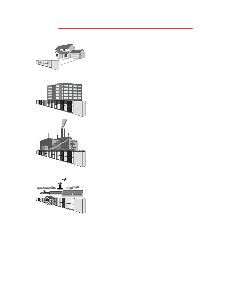
UL GATE CLASSIFICATIONS
Class I –
Residential vehicular gate operator
A vehicular gate operator (or system) intended for use in a home of
one-to four single family dwelling, or a garage or parking area
associated therewith.
Class II –
Commercial/General access vehicular gate operator
A vehicular gate operator (or system) intended for use in a commercial
location or building such as a multi-family housing unit (five or more
single family units) hotel, garages, retail store or other building
servicing the general public.
Class III –
Industrial/Limited access vehicular gate operator
A vehicular gate operator (or system) intended for use in a industrial
location or building such as a factory or loading dock area or other
locations not intended to service the general public.
Class IV –
Restricted access vehicular gate operator
A vehicular gate operator (or system) intended for use in a guarded
industrial location or building such as an airport security area or other
restricted access locations not servicing the general public, in which
unauthorized access is prevented via supervision by security
personnel.
6
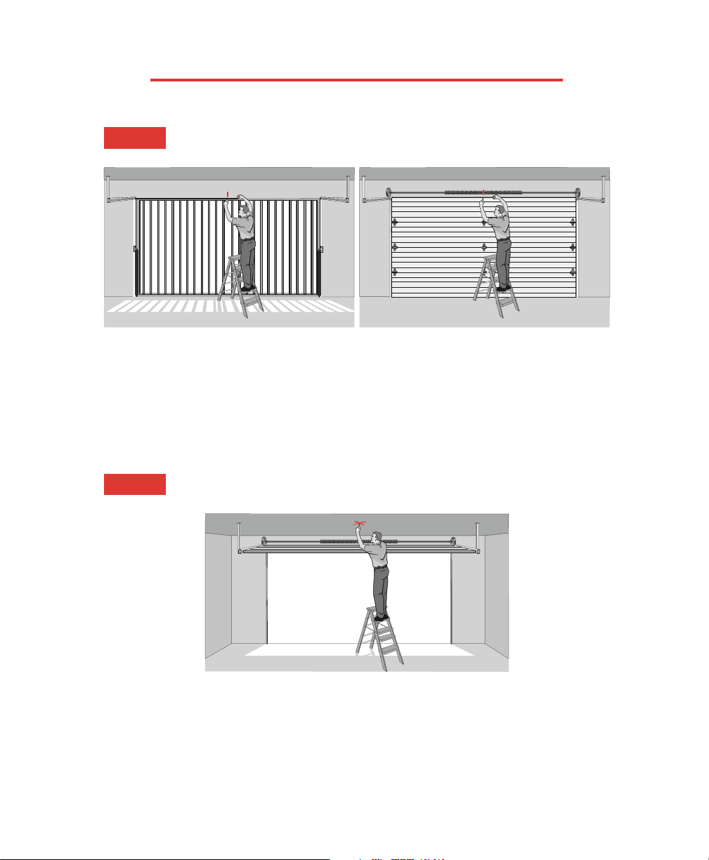
INSTALLATION OF OPERATOR
STEP 1
STEP 2
Make sure the hardware springs are balanced and the gate/door
opens and closes smoothly.
With the gate/door closed, mark the center of the gate/door.
Open the gate/door and mark the center point of the gate/door on the ceiling.
C
L
Gate
C
L
Door
Door Arm
Gate Arm
C
L
C
L
C
L
Header Bracket
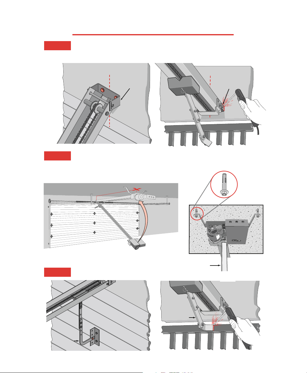
MOUNTING THE OPERATOR
Lift the operator and align with center mark on ceiling. Have someone hold the
operator in place or use something as a support post, and bolt to ceiling. (A support
post is not part of the operator. Use only for installation.)
Bolt or weld arm to gate/door.
STEP 3
STEP 4
STEP 5
Concrete
Anchor
1/2" x 3 1/2"
Support
Post
Make sure the header bracket is in the center of the opening. Bolt or weld the end of the
track (header bracket) to wall.
7
C
L
Header Bracket
C
L
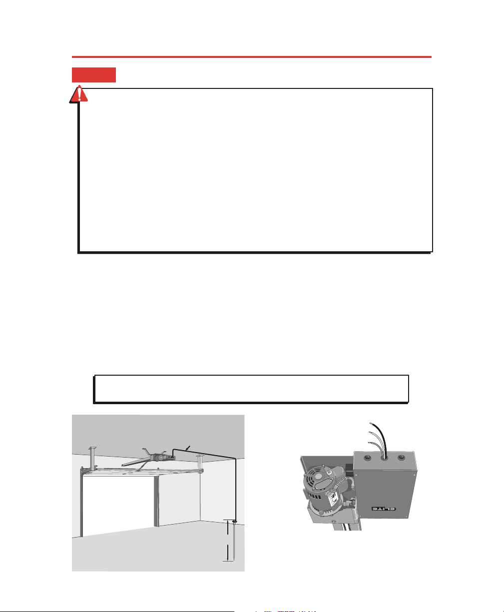
HOW TO CONNECT POWER (115VAC)
Proper grounding gives an electrical charge, such as from an electrical static discharge or a near lightning strike, a
path from which to dissipate its energy safely into the earth.
Without this path, the intense energy generated by lightning could be directed towards the operator. Although
nothing can absorb the tremendous power of a direct lightning strike, proper grounding can protect the operator
in most cases.
The ground wire must be a single, whole piece of wire. Never splice two wires for the ground wire. If you should
cut the ground wire too short, break it, or destroy its integrity, replace it with a single wire length.
Use the proper type earth ground rod for your local area. In certain circumstances, metal water pipes may be
allowed for grounding the operator. Check and follow all local codes for proper grounding procedures.
Black = 115 VAC Wire
White = Neutral Wire
Green = Earth Ground Wire
Minimum of
a 20-Amp
dedicated
circuit needed
for power.
Use UL listed
conduit to
enclose
power wires
Chamberlain Professional Products is not
responsible for improper installation or
failure to comply with all necessary local
building codes.
CAUTION: To avoid damaging gas, power, or other underground utility lines, contact
local underground utility locating companies before digging more than 18" deep.
STEP 6
Minimum 12 Gauge Ground
Wire connected to
HCT Earth Ground Wire
8 ft.
Earth Ground Rod
• Disconnect power at the fuse box BEFORE
proceeding. Operator MUST be properly
grounded and connected in accordance with
local electrical codes. NOTE: The operator
should be on a separate fused line of
adequate capacity.
• ALL electrical connections MUST be made by
a qualified individual.
• Do not install any wiring or attempt to run
the operator without consulting the wiring
diagram. We recommend that you install an
optional reversing edge BEFORE proceeding
with the control station installation.
• ALL power wiring should be on a dedicated
circuit and well protected. The location of the
power disconnect should be visible and
clearly labeled.
• ALL power and control wiring must be run in
separate conduit.
• BEFORE installing power wiring or control
stations, be sure to follow ALL specifications
and warnings described below. Failure to do
so may result in SEVERE INJURY to persons
and/or damage to operator.
• Entrapment protection devices MUST be
installed to protect anyone who may come
near a moving gate/door.
WARNING: To reduce the risk of SERIOUS INJURY or DEATH:
8
9
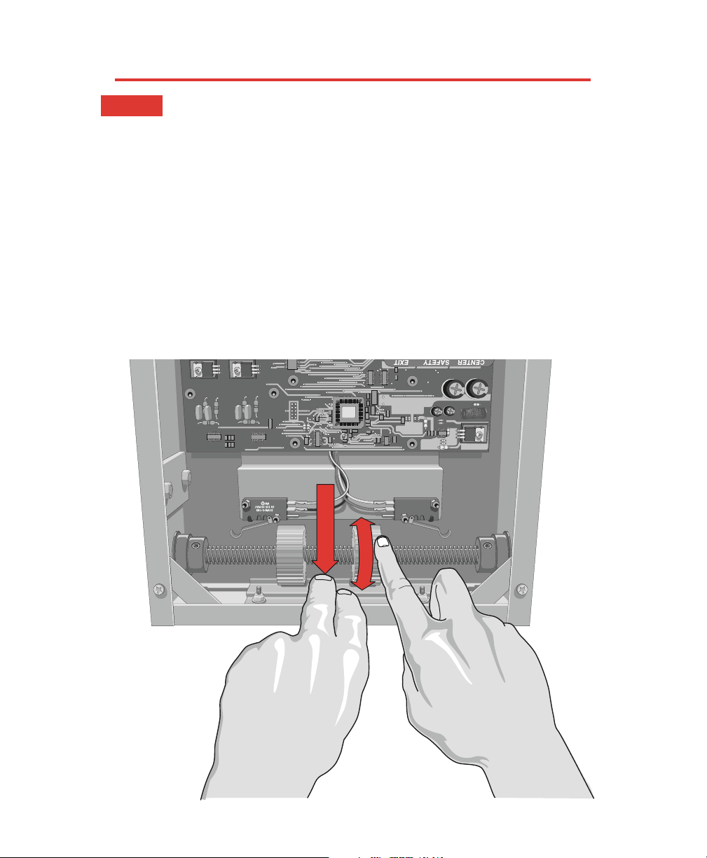
ADJUSTING TRAVELING DISTANCE
Before
Adjusting, Do the Following:
1. Turn the Power OFF!
2. Push the limit nut lock plate inward. Roll the nut to the direction desired.
3. Place the plate back in the notch.
4. Reapply power to operator.
5. If further adjustment is needed, repeat the process.
Push Plate
STEP 7
10
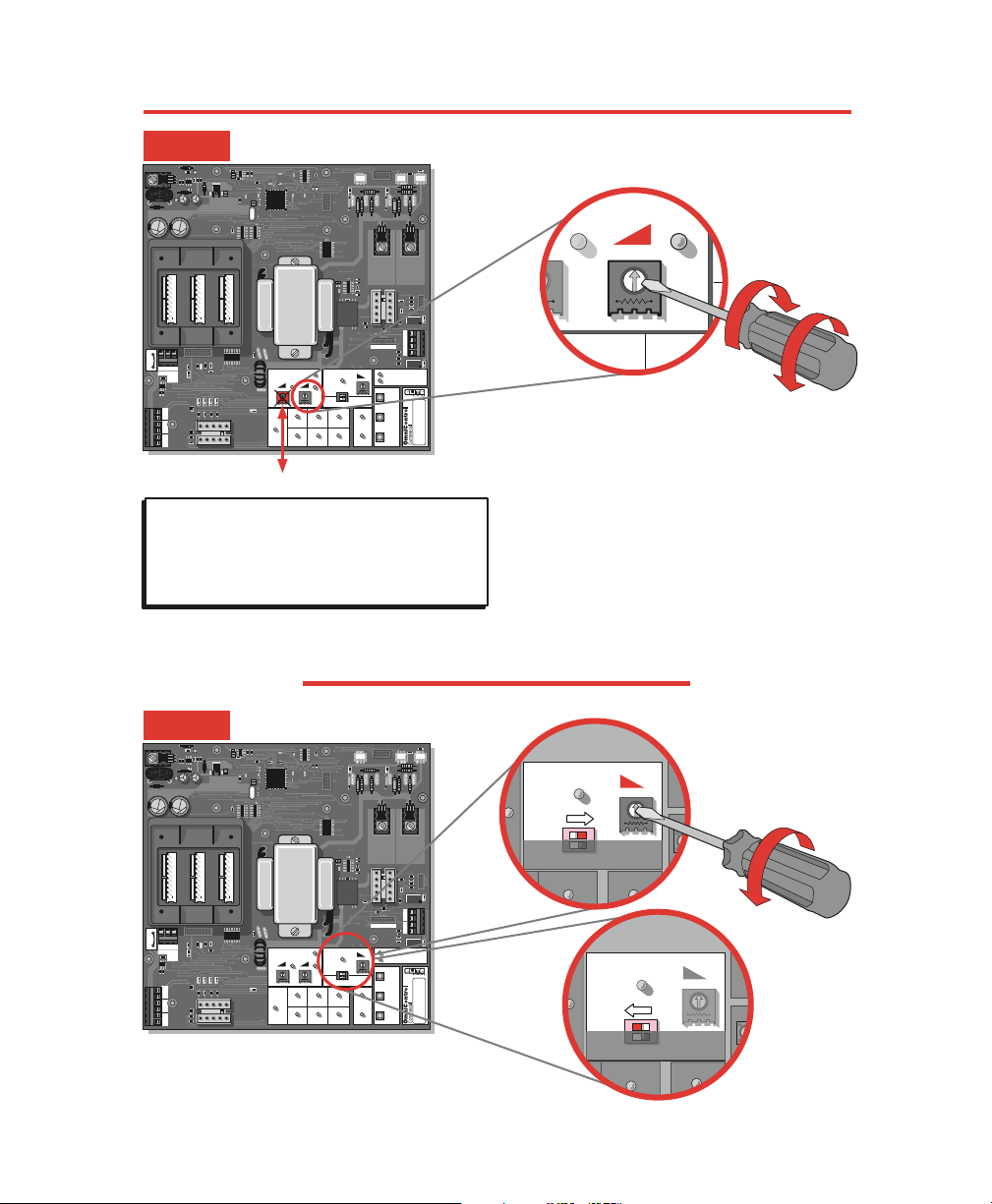
2-WAY ADJUSTABLE REVERSING SENSOR
ADJUSTABLE TIMER
CENTER SAFETY EXIT
CENTER SAFETY EXIT
FIRE
DEPT.
13
STRIKE
OPEN
RADIO
RECEIVER
TIMER
SYSTEM ON
EXIT
LOOP
ALARM
SENSOR
REVERSE
SENSOR
OPEN
STOPCLOSE
SAFETY
LOOP
CENTER
LOOP
GATE
LOCKED
60
POWER
OVERLOAD
OFF
W4
OPEN LEFT
DC-BACKUP
ALARMSENSOR
OPEN RIGHT
3
SENSORS
RESET
MOTOR
13
13
COMMAND
PROCESSED
ON
GB
MS LINK
A
MADE IN USA
CENTER SAFETY EXIT
CENTER SAFETY EXIT
FIRE
DEPT.
13
STRIKE
OPEN
RADIO
RECEIVER
TIMER
SYSTEM ON
EXIT
LOOP
ALARM
SENSOR
REVERSE
SENSOR
OPEN
STOPCLOSE
SAFETY
LOOP
CENTER
LOOP
GATE
LOCKED
60
POWER
OVERLOAD
OFF
W4
OPEN LEFT
DC-BACKUP
ALARMSENSOR
OPEN RIGHT
3
SENSORS
RESET
MOTOR
13
13
COMMAND
PROCESSED
ON
GB
MS LINK
A
MADE IN USA
TIMERTIMER
NSOR
60
OFF
OPEN LEFT OPEN RIGHT
3
13
ONON
Timer ON
TIMERTIMER
NSOR
60
OFFOFF
OPEN LEFT OPEN RIGHT
3
13
ON
Timer OFF
Set Timer
1 to 60 seconds
Timer can be set from 1 to 60 seconds (Timer ON),
For push open/push close type operation (Timer OFF).
DO NOT TOUCH ALARM SENSOR
The level of reverse sensitivity has to do with the weight
of the gate and the condition of installation.
Too sensitive = If the gate stops or reverses by itself.
Not sensitive enough = If the gate hits an obstruction or
vehicle and does not stop or reverse.
NOTE: If the power supply to the gate operator is
less than 99 volts, adjust the alarm by turning the
alarm adjustment counter-clockwise enough to
actuate the alarm when obstructed but not sensitive
enough for false triggering to occur.
Adjusted by Qualified Service Personnel
3
REVERSEREVERSE
SENSORSENSOR
13
Maximum
Sensitivity
Minimum
Sensitivity
Gate ONLY
STEP 8
STEP 9
11
Strike Open
Push Button
Strike Open
Push Button
24 Volts DC24 Volts DC
Fire Dept.
Key Switch
Fire Dept.
Key Switch
M/S LinkM/S Link
Class 2
Supply
Class 2
Supply
Center
Loop
Center
Loop
Safety
Loop
Safety
Loop
Radio
Receiver
Radio
Receiver
Exit
Loop
Exit
Loop
GG
BB
AA
––
++
OmniControl Surge Suppressor
P
/N
Q
4
1
0
P
a
te
n
t P
e
n
d
in
g
P
/N
Q
4
1
0
P
a
te
n
t P
e
n
d
in
g
®
Radio Power
Relay
24 Volt
3 Wire 24 VDC
Radio Receiver
4 Wire 24 VDC
Radio Receiver
External “Exit” Loop Detector
External “Safety” Loop Detector
Photo Beam
Phone
Entry
Push
Button
Card
Reader
Fire or
Any Key
Switch
4
7
8
0
H
E
L
P
9
1
2
3
5
6
++
––
Red 24 Volt
Grey
Black
Grey
7 1312111098
7
13
12
11
10
9
10
9
10
9
8
1 65
6
5
43
4
3
4
3
2
++
––
––
13
12
11
11
CENTER SAFETY EXIT
FIR
E
DEPT.
1
3
STRIKE
OPEN
RADIO
RECEIVER
TIM
ER
SYSTEM O
N
EXIT
LOOP
A
L
A
R
M
S
E
N
S
O
R
R
E
V
E
R
S
E
S
E
N
S
O
R
O
P
E
N
S
T
O
P
C
L
O
S
E
SAFETY
LO
OP
CENTER
LOOP
GATE
LO
CKED
60
POW
ER
OVER
LOAD
O
FF
W4
O
PEN LEFT
SEN
OPEN R
IGHT
3
SENS
ORS
RESET
M
OTO
R
1
3
1
3
C
O
M
M
A
N
D
P
R
O
C
E
S
S
E
D
ON
G
B
M
S
LIN
K
A
M
A
D
E
IN
U
S
A
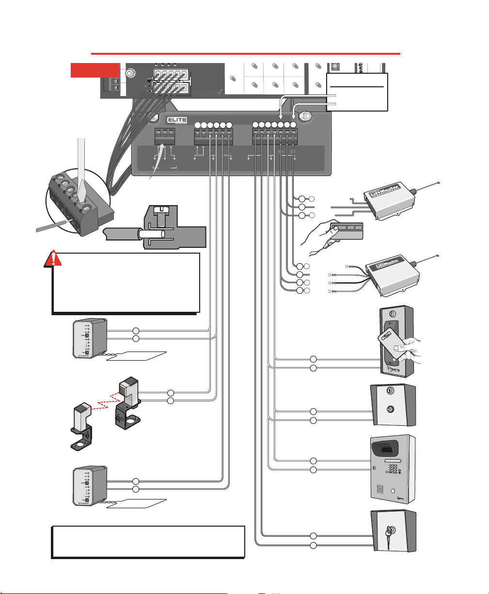
Ground (-)
24 VDC (+)
Output Power
Important: Terminals 11 and 12 are the only terminals
that will Open and Close with a single push of a button. All
other terminals will only open with a single push of a button.
Wire
Removable
Terminal
Connectors
Master/Second Link:
Not used in normal
installation
TERMINAL INPUT CONNECTIONS
STEP 10
WARNING: To ENSURE proper operation
of safety devices:
• ENSURE bare wire makes good contact
inside removable terminal connectors.
• DO NOT let wire insulation interfere with
connection.
 Loading...