


Lifebreath RNC155, RNC20, RNC10, RNC120D, RNC5-TPD User Manual
...Installation Instructions for Heat Recovery Ventilators with 2 Speed RNC Electronics
RNC Series
Models
RNC95
RNC155
RNC200
RNC10
RNC20
RNC120D
RNC5-TPD
Residential Heat Recovery Ventilators (HRV)
Manufactured with
2 Speed RNC Electronics
TI-RNC
0108
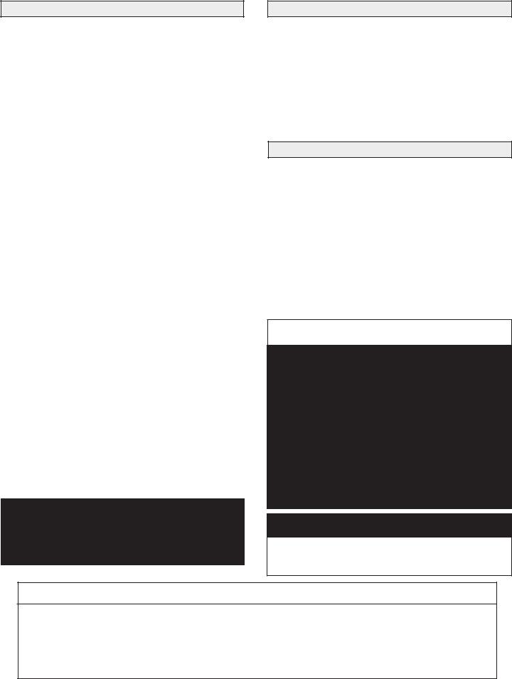
Table of Contents |
|
Introduction......................................................................... |
2 |
Engineering Data - RNC95 ............................................. |
3-4 |
Engineering Data - RNC155............................................... |
5 |
Engineering Data - RNC200............................................... |
6 |
Engineering Data - RNC10................................................. |
7 |
Engineering Data - RNC20................................................. |
8 |
Engineering Data - RNC5-TPD.......................................... |
9 |
Engineering Data - RNC120D .................................... |
10-11 |
Remote Control Devices................................................... |
12 |
Locating and Suspending the HRV .................................. |
13 |
Locating and Suspending the RNC120D.......................... |
14 |
Drain Connection.............................................................. |
15 |
Installation Methods ......................................................... |
16 |
Simplified Installation ...................................................... |
17 |
Partially Dedicated Installation......................................... |
18 |
Fully Dedicated Installation.............................................. |
19 |
Grilles and Weatherhoods................................................. |
20 |
Electrical........................................................................... |
21 |
Changing OFF to Standby/ |
|
Increasing Low Speed to Medium.................................... |
21 |
Mode DIP Switch Settings................................................ |
21 |
Wiring the Controls .......................................................... |
22 |
Defrost Operation ............................................................. |
23 |
Defrost Cycle DIP Switch Settings................................... |
23 |
Air Flow Balancing ..................................................... |
24-27 |
Interlocking HRV Operation to an |
|
Air Handler/Furnace Blower ............................................ |
28 |
Wiring Diagrams......................................................... |
29-31 |
Troubleshooting................................................................ |
32 |
Maintenance...................................................................... |
33 |
IMPORTANT
Please read this manual before installing the HRV
(Heat Recovery Ventilator).
Introduction
The Lifebreath HRV (Heat Recovery Ventilator) is designed to introduce fresh outdoor air into a building while exhausting an equal amount of stale indoor air.
During the heating season, heat energy from the stale exhausting air is transferred to the fresh, incoming air via Lifebreath's patented aluminum core.
During the air conditioning season, the HRV will help cool the incoming fresh air with the cooler stale exhausting air.
RNC Electronics
RNC electronics offers standard 2-speed operation of low/high. There is also an installer selectable 2-speed operation of medium low/high (refer to "Increasing Low Speed to Medium Low" in this manual).
The RNC circuit board also includes an interlock relay which is used to Interlock the HRV to an Air Handler/Furnace. Refer to "Interlocking HRV Operation to an Air Handler/Furnace Blower" in this manual.
We recommend using one of the Optional Main Controls (refer to "Remote Control Devices" in this manual) for normal operation.
 CAUTION
Before installation, careful consideration must be given to how this system will operate if connected to any other piece of mechanical equipment, i.e. a forced air furnace or air handler, operating at a higher static. After installation, the compatibility of the two pieces of equipment must be confirmed by measuring the airflows of the HRV (Heat Recovery Ventilator) by using the balancing procedure found in this manual.
NEVER install a ventilator in a situation where its normal operation, lack of operation or partial failure may result in the backdrafting or improper functioning of vented combustion equipment.
NOTE
Due to ongoing research and product development, specifications, ratings and dimensions are subject to change without notice.
Leave this Manual for the Homeowner
TO BE COMPLETED BY CONTRACTOR AFTER INSTALLATION
Installing Contractor _________________________________________Telephone / Contact _____________________
Serial Number______________________________________________Installation Date ________________________
Model _________________________________________________________________________________________
2
Engineering Data - HRV |
Model RNC95 |
|
|
THERMALLY CONDUCTIVE, PATENTED ALUMINUM CORE
The cross-flow heat recovery core transfers heat between the two airstreams. It is easily removed for cleaning or service.
MOTORS AND BLOWERS
Each air stream has one centrifugal blower driven by a common PSC motor. 2 speed fan operation.
FILTERS
Washable air filters in exhaust and supply air streams.
MOUNTING THE HRV
Four threaded inserts at corners of the cabinet designed to accept PVC reinforced polyester straps that are supplied with the unit.
DEFROST
Recirculating defrost system.
CASE
Twenty gauge prepainted galvanized steel (G60) for superior corrosion resistance. Insulated to prevent exterior condensation.
Drain connections 2 - 1/2" (12 mm) OD.
WEIGHT 52 lbs. (23.6 kg) Shipping Weight 56 lbs. (25.4 kg)
CONTROLS - HRV System Control
HRV defaults to LOW SPEED when plugged in. HIGH SPEED option is accessible by connecting remote controls to designated terminals inside electrical box of HRV.
Standard LOW SPEED SETTING can be increased to medium low.
Off (Standby)/Low or OFF/HIGH speed operation is also available.
OPTIONAL MAIN CONTROLS (only one main control can be installed on the system) 99-116 Dehumidistat Ventilation Control - Dehumidistat Dial, ON/OFF Switch and
LOW/HIGH Switch (3 wire) 20 gauge wire (min.) 100' length (max.)
99-2040 |
20/40 ON/OFF Dehumidistat - Dehumidistat Dial, ON/OFF Switch and 20/40 Switch. |
|
The 20/40 Switch will toggle from continuous low speed ventilation to intermittent low |
|
speed ventilation of 20 minutes fan ON and 40 minutes fan OFF. (4 wire) 20 gauge wire |
|
(min.) 100' length (max.) |
99-RECIRC |
Recirculation Control - Dehumidistat Dial, ON/OFF Switch and Recirculation Switch. |
|
The Recirculation Switch will toggle from continuous low speed ventilation to |
|
continuous low speed recirculation. (4 wire) 20 gauge wire (min.) 100' length (max.) |
99-130 |
Remote Dehumidistat - Dehumidistat Dial only. (2 wire) 20 gauge wire (min.) 100' |
|
length (max.) |
OPTIONAL TIMERS |
|
99-132 |
20 Minute Fan Timer - initiates high speed ventilation for 20 minutes. (3 wire) 20 gauge |
|
wire (min.) 100’ length |
99-104 |
Digital Electronic Timer- initiates high speed ventilation for 20, 40 or 60 minutes, (3 |
|
wire) 20 gauge wire (min.) 100' length |
99-101 |
60 Minute Crank Timer - initiates high speed ventilation for up to 60 minutes, (2 wire) |
|
20 gauge wire (min.) 100' length (max.) |
WARRANTY
Units carry a lifetime warranty on the heat recovery core and a 5 year replacement parts warranty.
Performance (HVI certified)
Net supply air flow in cfm (L/s) against external static pressure
E.S.P |
|
(external static pressure) |
[cfm (L/s)] |
@ 0.1" (25 Pa) |
76 (36) |
@ 0.2" (50 Pa) |
73 (34) |
@ 0.3" (75 Pa) |
70 (33) |
@ 0.4" (100 Pa) |
66 (31) |
@ 0.5" (125 Pa) |
60 (29) |
Max. Temperature Recovery |
88% |
|
|
|
|
Sensible Effectiveness |
|
|
@ 60 cfm (28 L/s) |
32°F (0°C) |
88% |
*Sensible Efficiency |
|
|
@ 60 cfm (28 L/s) |
32°F (0°C) |
75% |
*Sensible Efficiency |
|
|
@ 61 cfm (29 L/s) |
-13°F (-25°C) |
68% |
|
|
|
VAC @ 60HZ |
|
120 |
|
|
|
WATTS / Low speed. |
|
60 |
|
|
|
WATTS / High speed |
|
150 |
Amp rating |
|
0.9 |
*Sensible Efficiency – thermal **Latent Efficiency – moisture
Note: Effectiveness - based on temp. differential between the 2 airstreams Efficiency – takes into account all power inputs
|
80 |
|
|
|
|
5 - High Speed |
|
|
|
|
|
|
|
|
|
|
75 |
5 |
|
|
|
|
|
|
|
|
|
|
|
|
|
|
70 |
|
|
|
|
|
|
(cfm) |
65 |
|
|
|
|
|
|
Air Flow |
|
|
|
|
|
|
|
|
|
|
|
|
|
|
|
|
60 |
|
|
|
|
|
|
|
55 |
|
|
|
|
|
|
|
50 |
|
|
|
|
|
|
|
0 |
0.1 |
0.2 |
0.3 |
0.4 |
0.5 |
0.6 |
Static Pressure (in w.g.)
All units conform to CSA and UL standards
DIMENSIONS |
|
|
|
|
|
|
RNC95 |
18.5" |
|
knockout for |
Hanging |
|
|
inches (mm) |
(470 mm) |
|
side mounting of |
straps (4) |
Threaded |
|
|
EXHAUST return port |
|
|
|||
|
|
inserts (4) |
|
|||
|
|
|
6" round collar |
|
at corners |
|
|
|
|
converted to oval |
|
|
|
|
|
|
|
18.5" |
EXHAUST |
|
|
|
|
|
|
||
|
|
|
|
|
(470 mm) |
Stale Air |
|
(622mm) |
Removable |
|
SUPPLY |
to outside |
|
24.5" |
|
Fresh air |
5" round collar |
|||
Heat Recovery |
|
from outside |
|
|||
|
|
Core |
|
|
5" round collar |
EXHAUST |
|
|
|
minimum |
|
SUPPLY |
Return air |
|
|
|
|
from building |
||
|
|
|
|
Fresh air |
||
|
|
|
18 inches (459 mm) |
|
|
|
|
|
|
|
to building |
|
|
|
|
|
required for |
|
Choice of port location |
|
|
|
Drain Pan |
|
6" round |
||
|
|
service access |
|
Knockouts on top and |
||
|
|
|
(conv. to oval) |
|||
|
|
|
|
|||
|
|
|
|
|
side of unit (use 1 only) |
|
|
|
Drain spout |
|
16" |
collar |
|
|
FRONT |
|
SIDE |
(406 mm) |
TOP |
6" round (conv. to oval) |
|
|
|
collar supplied |
|||
Date: _______________________________________________ |
Contractor: __________________________________________ |
Tag: __________________________Qty:__________________ |
Supplier: ____________________________________________ |
Project: _____________________________________________ |
Quote#: _____________________________________________ |
Engineer:____________________________________________ |
Submitted by: ________________________________________ |
|
SP-RNC95 |
3

Port Configuration and Airflow |
Model RNC95 |
|
|
RNC95 Specifications
The RNC95 HRV (Heat Recovery Ventilator) has been designed to allow the installer to choose between two possible positions on the cabinet for the Stale Air Exhaust (from building) port. Illustrations in this manual show standard (side mounted) port location. The same specifications apply to both RNC95 setups, regardless of which port position is selected.
In order to make the RNC95 as space efficient as possible, the INDOOR supply and return ports are converted from round to oval shape. Overall size of the port remains the same. Simply bend a standard duct fitting to the correct shape, and attach to the oval port using the same method as for a round port.
Round port bent to oval
SIDE MOUNTED PORT |
TOP MOUNTED PORT |
standard location |
alternate location |
Variable Port Location / Installation (Model RNC95 only)
The exhaust return port collar is not factory installed. Installer may choose either side mounted or alternate top mounted port by simply removing one of the two knock-out plates and attaching a port collar (supplied). To remove knock-out plate, insert a utility knife into the knock-out slits and trace them completely to puncture protective film underneath. Then, cut the solid tabs between the slits, using tin snips or side cutters, and remove the knock-out plate. If any protective film still blocks the opening, remove it now.
RNC95 Air Flow
Stale air enters the FRONT RIGHT side port. The air will pass down the front half of the core, then up the back half of the core and out the RIGHT REAR port.
Fresh outdoor air will enter the LEFT REAR port and pass down the back half of the core. It will then pass up the front half of the core, and out the LEFT FRONT port.
4
Engineering Data - HRV |
Model RNC155 |
|
|
THERMALLY CONDUCTIVE, PATENTED ALUMINUM CORE
The cross-flow heat recovery core transfers heat between the two air streams. It is easily removed for cleaning or service.
MOTORS AND BLOWERS
Each air stream has one centrifugal blower driven by a common PSC motor. 2 speed fan operation.
FILTERS
Washable air filters in exhaust and supply air streams.
MOUNTING THE HRV
Four threaded inserts at corners of case designed to accept four reinforced polyester straps that are supplied with the unit.
DEFROST
Recirculating damper defrost system.
CASE
Twenty gauge prepainted galvanized steel (G60) for superior corrosion resistance. Insulated to prevent exterior condensation. Drain connections two - 1/2" (12mm) OD.
WEIGHT 71 lbs. (32.5 kg) SHIPPING WEIGHT 73 lbs. (33.5 kg)
CONTROLS - HRV System Control
HRV defaults to LOW SPEED when plugged in. HIGH SPEED option is accessible by connecting remote controls to designated terminals inside electrical box of HRV.
Standard LOW SPEED SETTING can be increased to medium low.
Off (Standby)/Low or OFF/HIGH speed operation is also available.
OPTIONAL MAIN CONTROLS (only one main control can be installed on the system)
99-116 |
Dehumidistat Ventilation Control - Dehumidistat Dial, ON/OFF Switch and |
|
LOW/HIGH Switch (3 wire) 20 gauge wire (min.) 100' length (max.) |
99-2040 |
20/40 ON/OFF Dehumidistat - Dehumidistat Dial, ON/OFF Switch and 20/40 Switch. |
|
The 20/40 Switch will toggle from continuous low speed ventilation to intermittent low |
|
speed ventilation of 20 minutes fan ON and 40 minutes fan OFF. (4 wire) 20 gauge wire |
|
(min.) 100' length (max.) |
99-RECIRC |
Recirculation Control - Dehumidistat Dial, ON/OFF Switch and Recirculation Switch. |
|
The Recirculation Switch will toggle from continuous low speed ventilation to continuous |
|
low speed recirculation. (4 wire) 20 gauge wire (min.) 100' length (max.) |
99-130 |
Remote Dehumidistat - Dehumidistat Dial only. (2 wire) 20 gauge wire (min.) 100' |
|
length (max.) |
OPTIONAL TIMERS |
|
99-132 |
20 Minute Fan Timer - initiates high speed ventilation for 20 minutes. (3 wire) 20 gauge |
|
wire (min.) 100’ length |
99-104 |
Digital Electronic Timer- initiates high speed ventilation for 20, 40 or 60 minutes, (3 |
|
wire) 20 gauge wire (min.) 100' length |
99-101 |
60 Minute Crank Timer - initiates high speed ventilation for up to 60 minutes, (2 wire) |
|
20 gauge wire (min.) 100' length (max.) |
WARRANTY
Units carry a lifetime warranty on the heat recovery core and a 5 year replacement parts warranty.
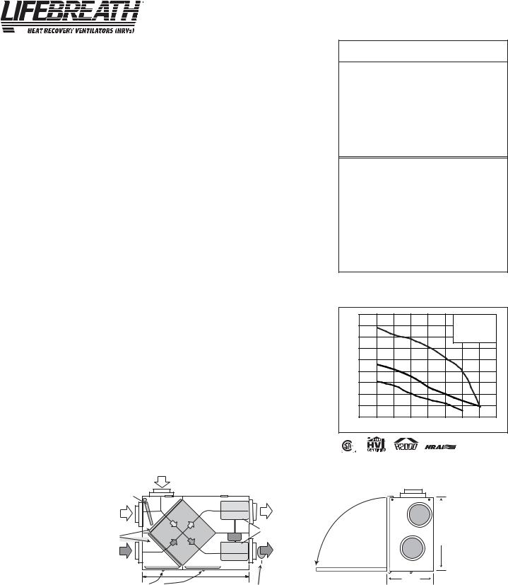
DIMENSIONS RNC155 inches (mm)
FRESH AIR |
STALE AIR |
|
FROM INSIDE |
||
FROM OUTSIDE |
||
|
||
RECIRCULATING |
FILTERS |
|
|
||
DEFROST |
|
|
DAMPER |
|
|
CORE |
BLOWERS |
|
MOTOR |
||
|
||
STALE AIR |
FRESH AIR |
|
TO OUTSIDE |
TO INSIDE |
|
|
33 5/8" |
|
CONDENSATE DRAINS |
(850mm) BALANCING DAMPER |
19" |
(483) |
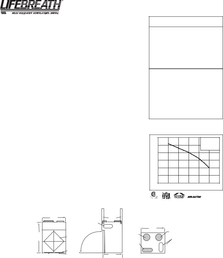
Performance (HVI certified)
Net supply air flow in cfm (L/s) against external static pressure
E.S.P |
|
|
(external static pressure) |
[cfm (L/s)] |
|
@ 0.1" (25 Pa) |
150 |
(71) |
@ 0.2" (50 Pa) |
146 |
(69) |
@ 0.3" (75 Pa) |
134 |
(63) |
@ 0.4" (100 Pa) |
121 |
(57) |
@ 0.5" (125 Pa) |
106 |
(50) |
@ 0.6" (150 Pa) |
92 |
(43) |
Max. Temperature Recovery |
78% |
|
|
|
|
Sensible Effectiveness |
|
|
@ 65 cfm (31 L/s) |
32°F (0°C) |
76% |
*Sensible Efficiency |
|
|
@ 65 cfm (31 L/s) |
32°F (0°C) |
64% |
*Sensible Efficiency |
|
|
@ 68 cfm (32 L/s) |
-13°F (-25°C) |
66% |
VAC @ 60HZ |
|
120 |
WATTS / Low speed. |
|
49 |
WATTS / High speed |
|
120 |
Amp rating |
|
1.4 |
*Sensible Efficiency – thermal **Latent Efficiency – moisture
Note: Effectiveness - based on temp. differential between the 2 airstreams Efficiency – takes into account all power inputs
|
160 |
|
|
|
|
3 - High Speed |
|
|
|
|
|
|
|
|
|
||
|
|
3 |
|
|
|
*2 - Medium Low Speed |
|
|
|
140 |
|
|
|
|
*1 - Low speed |
|
|
|
|
|
|
|
|
|
|
|
|
120 |
|
|
|
|
* Manufacturers Data |
|
|
|
|
|
|
|
|
|
|
|
Flow (cfm) |
100 |
|
|
|
|
|
|
|
80 |
|
|
|
|
|
|
|
|
Air |
|
|
|
|
|
|
|
|
|
2 |
|
|
|
|
|
|
|
|
|
|
|
|
|
|
|
|
|
60 |
|
|
|
|
|
|
|
|
|
1 |
|
|
|
|
|
|
|
40 |
|
|
|
|
|
|
|
|
20 |
|
|
|
|
|
|
|
|
0 |
0.1 |
0.2 |
0.3 |
0.4 |
0.5 |
0.6 |
0.7 |
Static Pressure (in w .g.)
All units conform to CSA and UL standards
*NOTE: Front clearance of 25 inches (635 mm) is recommended for servicing unit.
*All Duct Connections 6" (150mm)
14 3/4"
(375)
Date: _______________________________________________ |
Contractor: __________________________________________ |
Tag: __________________________Qty:__________________ |
Supplier: ____________________________________________ |
Project: _____________________________________________ |
Quote#: _____________________________________________ |
Engineer:____________________________________________ |
Submitted by: ________________________________________ |
5 |
SP-RNC155 |
|
Engineering Data - HRV |
Model RNC200 |
|
|
THERMALLY CONDUCTIVE, PATENTED ALUMINUM CORE
The cross-flow heat recovery core transfers heat between the two air streams. It is easily removed for cleaning or service.
MOTORS AND BLOWERS
Each air stream has one centrifugal blower driven by a common PSC motor. 2 speed fan operation.
FILTERS
Washable air filters in exhaust and supply air streams.
MOUNTING THE HRV
Four threaded inserts at corners of case designed to accept four reinforced polyester straps that are supplied with the unit.
DEFROST
Recirculating damper defrost system.
CASE
Twenty gauge prepainted galvanized steel (G60) for superior corrosion resistance. Insulated to prevent
exterior condensation. Drain connections |
two - 1/2" (12mm) OD. |
WEIGHT 71 lbs. (32.5 kg) |
SHIPPING WEIGHT 73 lbs. (33.5 kg) |
CONTROLS - HRV System Control
HRV defaults to LOW SPEED when plugged in. HIGH SPEED option is accessible by connecting remote controls to designated terminals inside electrical box of HRV.
Standard LOW SPEED SETTING can be increased to medium low.
Off (Standby)/Low or OFF/HIGH speed operation is also available.
OPTIONAL MAIN CONTROLS (only one main control can be installed on the system)
99-116 |
Dehumidistat Ventilation Control - Dehumidistat Dial, ON/OFF Switch and LOW/HIGH |
|
Switch (3 wire) 20 gauge wire (min.) 100' length (max.) |
99-2040 |
20/40 ON/OFF Dehumidistat - Dehumidistat Dial, ON/OFF Switch and 20/40 Switch. |
|
The 20/40 Switch will toggle from continuous low speed ventilation to intermittent low |
|
speed ventilation of 20 minutes fan ON and 40 minutes fan OFF. (4 wire) 20 gauge wire |
|
(min.) 100' length (max.) |
99-RECIRC |
Recirculation Control - Dehumidistat Dial, ON/OFF Switch and Recirculation Switch. |
|
The Recirculation Switch will toggle from continuous low speed ventilation to continuous |
|
low speed recirculation. (4 wire) 20 gauge wire (min.) 100' length (max.) |
99-130 |
Remote Dehumidistat - Dehumidistat Dial only. (2 wire) 20 gauge wire (min.) 100' length |
|
(max.) |
OPTIONAL TIMERS |
|
99-132 |
20 Minute Fan Timer - initiates high speed ventilation for 20 minutes. (3 wire) 20 gauge |
|
wire (min.) 100’ length |
99-104 |
Digital Electronic Timer- initiates high speed ventilation for 20, 40 or 60 minutes, (3 |
|
wire) 20 gauge wire (min.) 100' length |
99-101 |
60 Minute Crank Timer - initiates high speed ventilation for up to 60 minutes, (2 wire) |
|
20 gauge wire (min.) 100' length (max.) |
WARRANTY
Units carry a lifetime warranty on the heat recovery core and a 5 year replacement parts warranty.
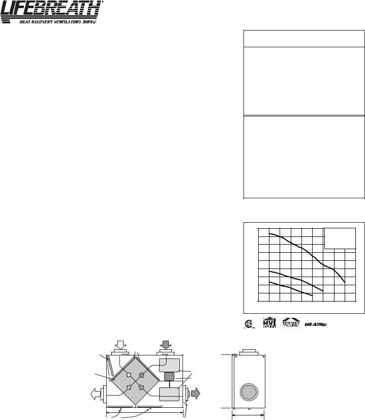
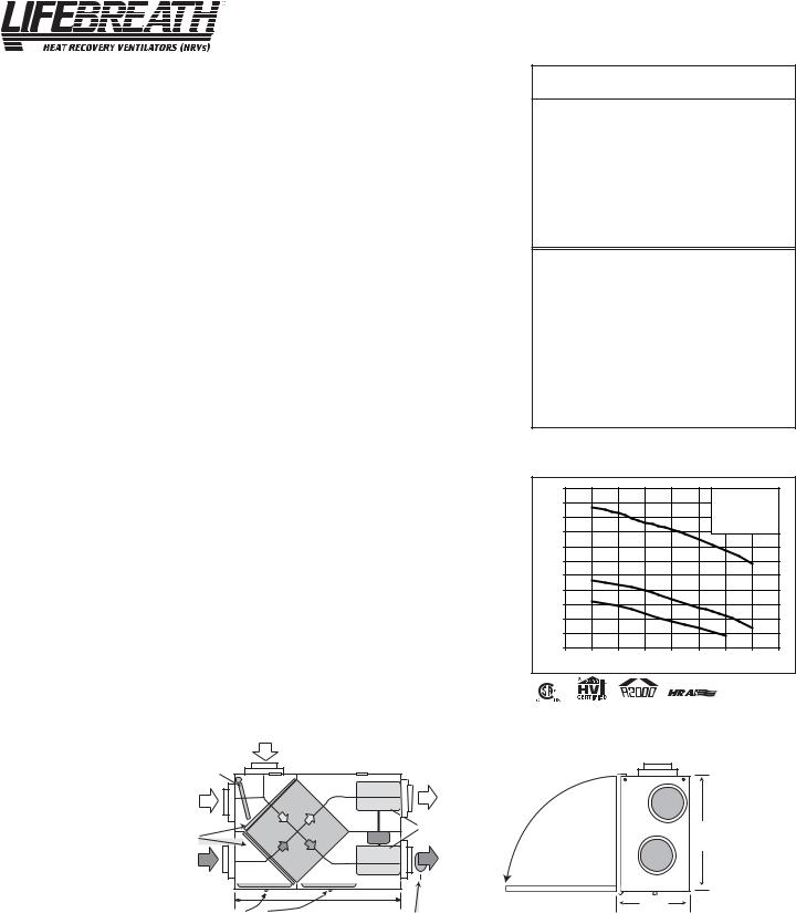
Dimensions RNC200
inches (mm)
FRESH AIR |
STALE AIR |
|
FROM OUTSIDE |
||
FROM INSIDE |
||
|
FILTERS
RECIRCULATING
DEFROST DAMPER
CORE |
BLOWERS |
|
MOTOR |
||
|
||
STALE AIR |
FRESH AIR |
|
TO OUTSIDE |
||
TO INSIDE |
||
|
||
|
33 5/8" |
CONDENSATE DRAINS (850 mm) BALANCING DAMPER
19" (483 mm)
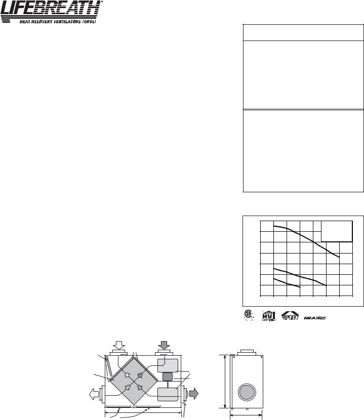
Performance (HVI certified)
Net supply air flow in cfm (L/s) against external static pressure
E.S.P |
|
|
(external static pressure) |
[cfm (L/s)] |
|
@ 0.1" (25 Pa) |
207 |
(97) |
@ 0.2" (50 Pa) |
200 |
(94) |
@ 0.3" (75 Pa) |
184 |
(87) |
@ 0.4" (100 Pa) |
171 |
(80) |
@ 0.5" (125 Pa) |
152 |
(71) |
@ 0.6" (150 Pa) |
130 |
(61) |
@ 0.7" (175 Pa) |
116 |
(55) |
@ 0.8" (200 Pa) |
86 |
(40) |
Max. Temperature Recovery |
74% |
|
|
|
|
Sensible Effectiveness |
|
|
@ 66 cfm (31 L/s) |
32°F (0°C) |
74% |
*Sensible Efficiency |
|
|
@ 66 cfm (31 L/s) |
32°F (0°C) |
64% |
*Sensible Efficiency |
|
|
@ 109 cfm (51 L/s) |
-13°F (-25°C) |
62% |
|
|
|
VAC @ 60HZ |
|
120 |
|
|
|
WATTS / Low speed. |
|
87 |
|
|
|
WATTS / High speed |
|
164 |
Amp rating |
|
1.4 |
*Sensible Efficiency – thermal **Latent Efficiency – moisture
Note: Effectiveness - based on temp. differential between the 2 airstreams Efficiency – takes into account all power inputs
|
220 |
|
|
|
|
|
3 - High Speed |
|
||
|
200 |
3 |
|
|
|
|
*2 - Medium Low Speed |
|||
|
|
|
|
|
|
*1 - Low speed |
|
|||
|
180 |
|
|
|
|
|
* Manufacturers Data |
|
||
|
|
|
|
|
|
|
|
|||
(cfm) |
160 |
|
|
|
|
|
|
|
|
|
140 |
|
|
|
|
|
|
|
|
|
|
Flow |
|
|
|
|
|
|
|
|
|
|
120 |
|
|
|
|
|
|
|
|
|
|
Air |
2 |
|
|
|
|
|
|
|
|
|
|
|
|
|
|
|
|
|
|
||
|
|
|
|
|
|
|
|
|
|
|
|
100 |
|
|
|
|
|
|
|
|
|
|
80 |
1 |
|
|
|
|
|
|
|
|
|
|
|
|
|
|
|
|
|
|
|
|
60 |
|
|
|
|
|
|
|
|
|
|
40 |
|
|
|
|
|
|
|
|
|
|
0 |
0.1 |
0.2 |
0.3 |
0.4 |
0.5 |
0.6 |
0.7 |
0.8 |
0.9 |
Static Pressure (in w.g.)
All units conform to CSA and UL standards
*NOTE: Front clearance
of 25 inches (635 mm)
is recommended for servicing unit.
*All Duct Connections 6" (150 mm)
14 3/4"
(375 mm)
Date: _______________________________________________ |
Contractor: __________________________________________ |
Tag: __________________________Qty:__________________ |
Supplier: ____________________________________________ |
Project: _____________________________________________ |
Quote#: _____________________________________________ |
Engineer:____________________________________________ |
Submitted by: ________________________________________ |
6 |
SP-RNC200 |
|
Engineering Data - HRV |
Model RNC10 |
|
|
THERMALLY CONDUCTIVE, PATENTED ALUMINUM CORE
The cross-flow heat recovery core transfers heat between the two air streams. It is easily removed for cleaning or service.
MOTORS AND BLOWERS
Each air stream has one centrifugal blower driven by a common PSC motor. 2 speed fan operation.
FILTERS
Washable air filters in exhaust and supply air streams.
MOUNTING THE HRV
Four threaded inserts at corners of case designed to accept four PVC reinforced polyester straps that are supplied with the unit.
DEFROST
Damper defrost system; defrosts automatically as the outdoor temperature falls.
CASE
Twenty gauge prepainted galvanized steel (G60) for superior corrosion resistance. Insulated to prevent exterior condensation. Drain connections two - 1/2" (12mm) OD.
WEIGHT 63 lbs. (28.7 kg) SHIPPING WEIGHT 67 lbs. (30.4 kg)
CONTROLS - HRV System Control
HRV defaults to LOW SPEED when plugged in. HIGH SPEED option is accessible by connecting remote controls to designated terminals inside electrical box of HRV.
Standard LOW SPEED SETTING can be increased to medium low.
Off (Standby)/Low or OFF/HIGH speed operation is also available.
OPTIONAL MAIN CONTROLS (only one main control can be installed on the system)
99-116 |
Dehumidistat Ventilation Control - Dehumidistat Dial, ON/OFF Switch and LOW/HIGH |
|
Switch (3 wire) 20 gauge wire (min.) 100' length (max.) |
99-2040 |
20/40 ON/OFF Dehumidistat - Dehumidistat Dial, ON/OFF Switch and 20/40 Switch. |
|
The 20/40 Switch will toggle from continuous low speed ventilation to intermittent low |
|
speed ventilation of 20 minutes fan ON and 40 minutes fan OFF. (4 wire) 20 gauge wire |
|
(min.) 100' length (max.) |
99-130 |
Remote Dehumidistat - Dehumidistat Dial only. (2 wire) 20 gauge wire (min.) 100' length |
|
(max.) |
OPTIONAL TIMERS |
|
99-132 |
20 Minute Fan Timer - initiates high speed ventilation for 20 minutes. (3 wire) 20 gauge |
|
wire (min.) 100’ length |
99-104 |
Digital Electronic Timer- initiates high speed ventilation for 20, 40 or 60 minutes, (3 |
|
wire) 20 gauge wire (min.) 100' length |
99-101 |
60 Minute Crank Timer - initiates high speed ventilation for up to 60 minutes, (2 wire) |
|
20 gauge wire (min.) 100' length (max.) |
WARRANTY
Units carry a lifetime warranty on the heat recovery core and a 5 year replacement parts warranty.
Performance (HVI certified)
Net supply air flow in cfm (L/s) against external static pressure
E.S.P |
|
|
(external static pressure) |
[cfm (L/s)] |
|
@ 0.1" (25 Pa) |
177 |
(83) |
@ 0.2" (50 Pa) |
164 |
(77) |
@ 0.3" (75 Pa) |
156 |
(73) |
@ 0.4" (100 Pa) |
143 |
(67) |
@ 0.5" (125 Pa) |
123 |
(58) |
@ 0.6" (150 Pa) |
100 |
(47) |
@ 0.7" (175 Pa) |
38 |
(18) |
Max. Temperature Recovery |
78% |
|
|
|
|
Sensible Effectiveness |
|
|
@ 67 cfm (32 L/s) |
32°F (0°C) |
76% |
*Sensible Efficiency |
|
|
@ 67 cfm (32 L/s) |
32°F (0°C) |
66% |
*Sensible Efficiency |
|
|
@ 68 cfm (32 L/s) |
-13°F (-25°C) |
60% |
|
|
|
VAC @ 60HZ |
|
120 |
|
|
|
WATTS / Low speed. |
|
63 |
|
|
|
WATTS / High speed |
|
173 |
|
|
|
Amp rating |
|
1.4 |
*Sensible Efficiency - thermal **Latent Efficiency - moisture
Note: Effectiveness - based on temp. differential between the 2 airstreams Efficiency - takes into account all power inputs
|
200 |
|
|
|
|
|
3 - High Speed |
|
|
|
|
|
|
|
|
|
|
||
|
180 |
|
|
|
|
|
*2 - Medium Low Speed |
||
|
3 |
|
|
|
|
*1 - Low speed |
|
||
|
|
|
|
|
|
|
|
|
|
|
160 |
|
|
|
|
|
*Manufacturer’s Data |
|
|
|
|
|
|
|
|
|
|
||
|
140 |
|
|
|
|
|
|
|
|
(cfm) |
120 |
2 |
|
|
|
|
|
|
|
Flow |
|
|
|
|
|
|
|
|
|
100 |
|
|
|
|
|
|
|
|
|
Air |
|
|
|
|
|
|
|
|
|
|
1 |
|
|
|
|
|
|
|
|
|
80 |
|
|
|
|
|
|
|
|
|
|
|
|
|
|
|
|
|
|
|
60 |
|
|
|
|
|
|
|
|
|
40 |
|
|
|
|
|
|
|
|
|
20 |
|
|
|
|
|
|
|
|
|
0 |
0.1 |
0.2 |
0.3 |
0.4 |
0.5 |
0.6 |
0.7 |
0.8 |
Static Pressure (in w.g.)
All units conform to CSA and UL standards
Dimensions |
FRESH AIR |
RNC10 |
FROM OUTSIDE |
|
inches (mm) |
DEFROST |
STALE AIR |
DAMPER |
TO OUTSIDE |
|
|
DEFROST |
|
|
PORT |
|
|
FILTERS |
BLOWERS |
|
|
|
|
STALE AIR |
FRESH AIR |
|
TO INSIDE |
|
|
FROM INSIDE |
|
|
|
|
|
|
33-5/8" |
|
CONDENSATE DRAINS |
BALANCING DAMPER |
|
|
*NOTE:
Front clearance of 25 inches (635 mm) is recommended for servicing unit.
14 3/4"
(375)
19" |
|
(483) |
|
*All Duct Connections 6"(150mm)
Date: _______________________________________________ |
Contractor: __________________________________________ |
Tag: __________________________Qty:__________________ |
Supplier: ____________________________________________ |
Project: _____________________________________________ |
Quote#: _____________________________________________ |
Engineer:____________________________________________ |
Submitted by: ________________________________________ |
7 |
SP-RNC10 |
Engineering Data - HRV |
Model RNC20 |
|
|
THERMALLY CONDUCTIVE, PATENTED ALUMINUM CORE
The cross-flow heat recovery core transfers heat between the two air streams. It is easily removed for cleaning or service.
MOTORS AND BLOWERS
Each air stream has one centrifugal blower driven by a common PSC motor. 2 speed fan operation.
FILTERS
Washable air filters in exhaust and supply air streams.
MOUNTING THE HRV
Four threaded inserts at corners of case designed to accept four PVC reinforced polyester straps that are supplied with the unit.
DEFROST
Damper defrost system; defrosts automatically as the outdoor temperature falls.
CASE
Twenty gauge prepainted galvanized steel (G60) for superior corrosion resistance. Insulated to prevent exterior condensation. Drain connections two - 1/2" (12mm) OD.
WEIGHT 63 lbs. (28.7 kg) SHIPPING WEIGHT 67 lbs. (30.4 kg)
CONTROLS - HRV System Control
HRV defaults to LOW SPEED when plugged in. HIGH SPEED option is accessible by connecting remote controls to designated terminals inside electrical box of HRV.
Standard LOW SPEED SETTING can be increased to medium low.
Off (Standby)/Low or OFF/HIGH speed operation is also available.
OPTIONAL MAIN CONTROLS (only one main control can be installed on the system)
99-116 |
Dehumidistat Ventilation Control - Dehumidistat Dial, ON/OFF Switch and LOW/HIGH |
|
Switch (3 wire) 20 gauge wire (min.) 100' length (max.) |
99-RECIRC |
Recirculation Control - Dehumidistat Dial, ON/OFF Switch and Recirculation Switch. |
|
The Recirculation Switch will toggle from continuous low speed ventilation to continuous |
|
low speed recirculation. (4 wire) 20 gauge wire (min.) 100' length (max.) |
99-130 |
Remote Dehumidistat - Dehumidistat Dial only. (2 wire) 20 gauge wire (min.) 100' length |
|
(max.) |
OPTIONAL TIMERS |
|
99-132 |
20 Minute Fan Timer - initiates high speed ventilation for 20 minutes. (3 wire) 20 gauge |
|
wire (min.) 100’ length |
99-104 |
Digital Electronic Timer- initiates high speed ventilation for 20, 40 or 60 minutes, (3 |
|
wire) 20 gauge wire (min.) 100' length |
99-101 |
60 Minute Crank Timer - initiates high speed ventilation for up to 60 minutes, (2 wire) |
|
20 gauge wire (min.) 100' length (max.) |
WARRANTY
Units carry a lifetime warranty on the heat recovery core and a 5 year replacement parts warranty.
Performance (HVI certified)
Net supply air flow in cfm (L/s) against external static pressure
E.S.P |
|
(external static pressure) |
[cfm (L/s)] |
@ 0.1" (25 Pa) |
214 (101) |
@ 0.2" (50 Pa) |
206 (97) |
@ 0.3" (75 Pa) |
193 (91) |
@ 0.4" (100 Pa) |
184 (87) |
@ 0.5" (125 Pa) |
170 (80) |
@ 0.6" (150 Pa) |
155 (73) |
@ 0.7" (175 Pa) |
137 (65) |
Max. Temperature Recovery |
69% |
|
|
|
|
Sensible Effectiveness |
|
|
@ 119 cfm (56 L/s) |
32°F (0°C) |
67% |
*Sensible Efficiency |
|
|
@ 119 cfm (56 L/s) |
32°F (0°C) |
60% |
*Sensible Efficiency |
|
|
@ 117 cfm (55 L/s) |
-13°F (-25°C) |
60% |
|
|
|
VAC @ 60HZ |
|
120 |
|
|
|
WATTS / Low speed. |
|
70 |
|
|
|
WATTS / High speed |
|
182 |
|
|
|
Amp rating |
|
1.4 |
*Sensible Efficiency - thermal **Latent Efficiency - moisture
Note: Effectiveness - based on temp. differential between the 2 airstreams Efficiency - takes into account all power inputs
|
240 |
|
|
|
|
|
3 - High Speed |
|
|
|
|
|
|
|
|
|
|
||
|
220 |
|
|
|
|
|
*2 - Medium Low Speed |
||
|
3 |
|
|
|
|
*1 - Low speed |
|
||
|
|
|
|
|
|
|
|||
|
200 |
|
|
|
|
|
|
|
|
|
180 |
|
|
|
|
|
*Manufacturer’s data |
|
|
|
|
|
|
|
|
|
|
|
|
(cfm) |
160 |
|
|
|
|
|
|
|
|
140 |
|
|
|
|
|
|
|
|
|
Flow |
|
|
|
|
|
|
|
|
|
120 |
|
|
|
|
|
|
|
|
|
Air |
2 |
|
|
|
|
|
|
|
|
|
|
|
|
|
|
|
|
||
|
100 |
|
|
|
|
|
|
|
|
|
80 |
1 |
|
|
|
|
|
|
|
|
|
|
|
|
|
|
|
|
|
|
60 |
|
|
|
|
|
|
|
|
|
40 |
|
|
|
|
|
|
|
|
|
20 |
|
|
|
|
|
|
|
|
|
0 |
0.1 |
0.2 |
0.3 |
0.4 |
0.5 |
0.6 |
0.7 |
0.8 |
Static Pressure (in w.g.)
|
|
|
All units conform to CSA and UL standards |
||
Dimensions |
FRESH AIR |
|
|
|
|
FROM OUTSIDE |
|
|
|
|
|
RNC20 |
DEFROST |
STALE AIR |
|
|
|
inches (mm) |
DAMPER |
TO OUTSIDE |
|
|
|
|
|
|
|
||
|
DEFROST |
|
|
|
|
|
PORT |
|
|
|
(483) |
|
FILTERS |
BLOWERS |
*NOTE: |
19" |
|
|
|
|
|||
|
|
|
|
||
|
|
|
Front clearance of |
|
|
|
|
|
25 inches (635 mm) |
|
|
|
|
|
is recommended |
|
|
|
STALE AIR |
FRESH AIR |
for servicing unit. |
|
|
|
|
|
|
||
|
TO INSIDE |
|
|
|
|
|
FROM INSIDE |
|
14 3/4" |
|
|
|
|
|
|
||
|
33-5/8" |
|
|
|
|
|
BALANCING DAMPER |
|
(375) |
|
|
|
CONDENSATE DRAINS |
|
|
|
|
|
|
|
|
|
|
*All Duct Connections 6"(150mm)
Date: _______________________________________________ |
Contractor: __________________________________________ |
Tag: __________________________Qty:__________________ |
Supplier: ____________________________________________ |
Project: _____________________________________________ |
Quote#: _____________________________________________ |
Engineer:____________________________________________ |
Submitted by: ________________________________________ |
8 |
SP-RNC20 |
Engineering Data - HRV |
Model RNC5-TPD |
|
|
THERMALLY CONDUCTIVE, PATENTED ALUMINUM CORE
The cross-flow heat recovery core transfers heat between the two airstreams. It is easily removed for cleaning or service.
MOTORS AND BLOWERS
Each air stream has an independent motorized impeller. 2 speed fan operation.
FILTERS
Washable air filters in exhaust and supply air streams.
DEFROST
Recirculating damper defrost system.
CASE
Twenty gauge prepainted galvanized steel (G60) for superior corrosion resistance. Insulated to prevent exterior condensation. Drain connections 1/2" (12 mm) OD.
MOUNTING THE HRV
Four threaded inserts at corners of case designed to accept four reinforced polyester straps that are supplied with the unit.
DUCT CONNECTIONS
4 - 5” (127 mm) duct connections.
WEIGHT 61 lbs. (28 kg) SHIPPING WEIGHT 64 lbs. (29 kg)
CONTROLSHRV System Control
HRV defaults to user selected speed from switch on top of cabinet when plugged in. HIGH SPEED option is accessible by connecting remote controls to designated terminals inside electrical box of HRV.
OFF(Standby)/LOW or OFF/HIGH speed operation is also available.
OPTIONAL MAIN CONTROLS (only one main control can be installed on the system) 99-116 Dehumidistat Ventilation Control - Dehumidistat Dial, ON/OFF Switch and
LOW/HIGH Switch (3 wire) 20 gauge wire (min.) 100' length (max.)
99-2040 |
20/40 ON/OFF Dehumidistat - Dehumidistat Dial, ON/OFF Switch and 20/40 Switch. |
|
The 20/40 Switch will toggle from continuous low speed ventilation to intermittent low |
|
speed ventilation of 20 minutes fan ON and 40 minutes fan OFF. (4 wire) 20 gauge wire |
|
(min.) 100' length (max.) |
99-RECIRC |
Recirculation Control - Dehumidistat Dial, ON/OFF Switch and Recirculation Switch. |
|
The Recirculation Switch will toggle from continuous low speed ventilation to |
|
continuous low speed recirculation. (4 wire) 20 gauge wire (min.) 100' length (max.) |
99-130 |
Remote Dehumidistat - Dehumidistat Dial only. (2 wire) 20 gauge wire (min.) 100' |
|
length (max.) |
OPTIONAL TIMERS |
|
99-132 |
20 Minute Fan Timer - initiates high speed ventilation for 20 minutes. (3 wire) 20 |
|
gauge wire (min.) 100’ length |
99-104 |
Digital Electronic Timer- initiates high speed ventilation for 20, 40 or 60 minutes, (3 |
|
wire) 20 gauge wire (min.) 100' length |
99-101 |
60 Minute Crank Timer - initiates high speed ventilation for up to 60 minutes, (2 wire) |
|
20 gauge wire (min.) 100' length (max.) |
WARRANTY
Units carry a lifetime warranty on the heat recovery core and a 5 year replacement parts warranty.
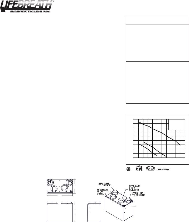
Performance (H.V.I. certified)
Net supply air flow in cfm (L/s) against external static pressure
E.S.P |
|
|
(external static pressure) |
[cfm (L/s)] |
|
@ 0.1" (25 Pa) |
169 |
(80) |
@ 0.2" (50 Pa) |
156 |
(73) |
@ 0.3" (75 Pa) |
149 |
(70) |
@ 0.4" (100 Pa) |
136 |
(64) |
@ 0.5" (125 Pa) |
126 |
(59) |
@ 0.6" (150 Pa) |
116 |
(54) |
@ 0.7" (175 Pa) |
103 |
(48) |
@ 0.8" (200 Pa) |
89 |
(42) |
@ 0.9" (225 Pa) |
77 |
(36) |
@ 1.0" (250 Pa) |
58 |
(27) |
Max. Temperature Recovery |
78% |
|
|
|
|
Sensible Effectiveness |
|
|
@ 66 cfm (31 L/s) |
32°F (0°C) |
74% |
*Sensible Efficiency |
|
|
@ 66 cfm (31 L/s) |
32°F (0°C) |
61% |
*Sensible Efficiency |
|
|
@ 76 cfm (36 L/s) |
-13°F (-25°C) |
63% |
|
|
|
VAC @ 60HZ |
|
120 |
|
|
|
WATTS / Low speed. |
|
69 |
|
|
|
WATTS / High speed |
|
147 |
|
|
|
Amp rating |
|
1.7 |
*Sensible Efficiency - thermal **Latent Efficiency - moisture
Note: Effectiveness - based on temp. differential between the 2 airstreams Efficiency - takes into account all power inputs
|
180 |
|
|
|
|
|
|
|
3 - High Speed |
|
|
|
|
|
3 |
|
|
|
|
|
|
|
|
||
|
160 |
|
|
|
|
|
|
*2 - Medium Low Speed |
||||
|
|
|
|
|
|
|
|
*1 - Low speed |
|
|
||
|
140 |
|
|
|
|
|
|
|
* Manufacturers Data |
|
||
|
|
|
|
|
|
|
|
|
|
|||
|
120 |
|
|
|
|
|
|
|
|
|
|
|
(cfm) |
100 |
|
|
|
|
|
|
|
|
|
|
|
|
|
|
|
|
|
|
|
|
|
|
|
|
Flow |
80 |
|
2 |
|
|
|
|
|
|
|
|
|
|
|
|
|
|
|
|
|
|
|
|
||
Air |
|
1 |
|
|
|
|
|
|
|
|
|
|
60 |
|
|
|
|
|
|
|
|
|
|
||
|
|
|
|
|
|
|
|
|
|
|
|
|
|
40 |
|
|
|
|
|
|
|
|
|
|
|
|
20 |
|
|
|
|
|
|
|
|
|
|
|
|
0 |
|
|
|
|
|
|
|
|
|
|
|
|
0 |
0.1 |
0.2 |
0.3 |
0.4 |
0.5 |
0.6 |
0.7 |
0.8 |
0.9 |
1 |
1.1 |
Static Pressure (in w.g.)
All units conform to CSA and UL standards
Dimensions |
|
|
RNC5-TPD |
15” |
|
inches (mm) |
(378 mm) |
|
|
|
|
|
27” |
|
|
(690 mm) |
|
|
2-1/4” |
|
|
(57 mm) |
SPEED |
|
|
|
|
|
SELECTION |
|
18-3/4” |
SWITCH |
|
(475 mm) |
|
Date: _______________________________________________ |
Contractor: __________________________________________ |
|
Tag: __________________________Qty:__________________ |
Supplier: ____________________________________________ |
|
Project: _____________________________________________ |
Quote#: _____________________________________________ |
|
Engineer:____________________________________________ |
Submitted by: ________________________________________ |
|
9 |
SP-RNC5-TPD |
Engineering Data - HRV |
Model RNC120D |
|
|
THERMALLY CONDUCTIVE, PATENTED ALUMINUM CORE
The cross-flow heat recovery core transfers heat between the two airstreams. It is easily removed for cleaning or service.
MOTORS AND BLOWERS
Each air stream has an independent motorized impeller. 2 speed fan operation.
FILTERS
Washable air filters in exhaust and supply air streams.
MOUNTING THE HRV
Four threaded inserts at corners of case designed to accept four reinforced polyester straps that are supplied with the unit.
DEFROST
Recirculating damper defrost system.
CASE
Twenty gauge prepainted galvanized steel (G60) for superior corrosion resistance. Insulated to prevent exterior condensation. Drain connections- 1/2" (12 mm) OD.
DUCT CONNECTIONS
5” duct connections.
WEIGHT 42 lbs. (19 kg.) SHIPPING WEIGHT 45 lbs. (20.5 kg.)
CONTROLS - HRV System Control
HRV defaults to LOW SPEED when plugged in. HIGH SPEED option is accessible by connecting remote controls to designated terminals inside electrical box of HRV.
Standard LOW SPEED SETTING can be increased to medium low. Off (Standby)/Low or OFF/HIGH speed operation is also available.
OPTIONAL MAIN CONTROLS (only one main control can be installed on the system)
99-116 |
Dehumidistat Ventilation Control - Dehumidistat Dial, ON/OFF Switch and |
|
LOW/HIGH Switch (3 wire) 20 gauge wire (min.) 100' length (max.) |
99-2040 |
20/40 ON/OFF Dehumidistat - Dehumidistat Dial, ON/OFF Switch and 20/40 Switch. |
|
The 20/40 Switch will toggle from continuous low speed ventilation to intermittent low |
|
speed ventilation of 20 minutes fan ON and 40 minutes fan OFF. (4 wire) 20 gauge wire |
|
(min.) 100' length (max.) |
99-RECIRC |
Recirculation Control - Dehumidistat Dial, ON/OFF Switch and Recirculation Switch. |
|
The Recirculation Switch will toggle from continuous low speed ventilation to continuous |
|
low speed recirculation. (4 wire) 20 gauge wire (min.) 100' length (max.) |
99-130 |
Remote Dehumidistat - Dehumidistat Dial only. (2 wire) 20 gauge wire (min.) 100' |
|
length (max.) |
OPTIONAL TIMERS |
|
99-132 |
20 Minute Fan Timer - initiates high speed ventilation for 20 minutes. (3 wire) 20 gauge |
|
wire (min.) 100’ length |
99-104 |
Digital Electronic Timer- initiates high speed ventilation for 20, 40 or 60 minutes, (3 |
|
wire) 20 gauge wire (min.) 100' length |
99-101 |
60 Minute Crank Timer - initiates high speed ventilation for up to 60 minutes, (2 wire) |
|
20 gauge wire (min.) 100' length (max.) |
WARRANTY
Units carry a lifetime warranty on the heat recovery core and a 5 year replacement parts warranty.
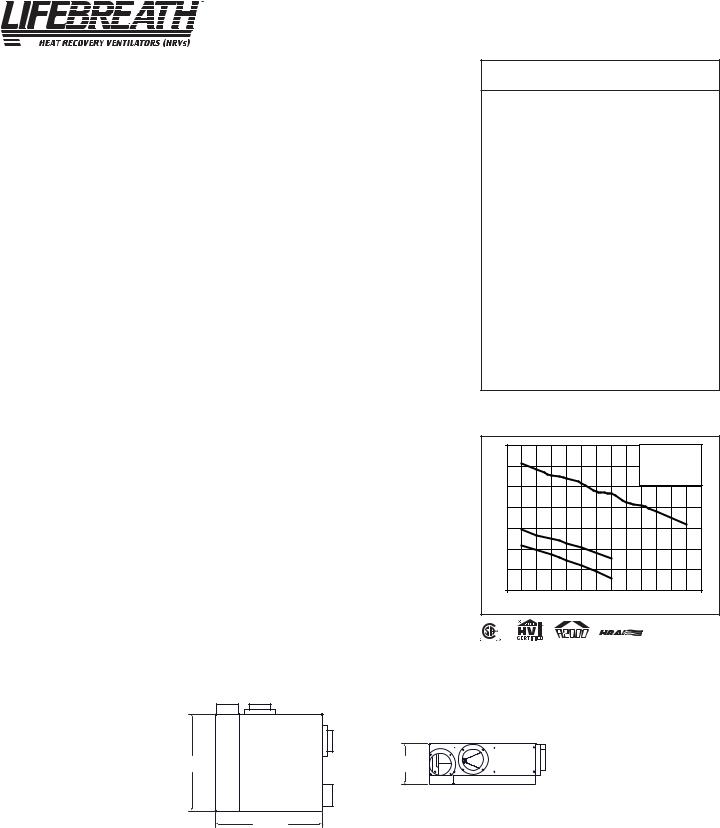
Performance (HVI certified)
Net supply air flow in cfm (L/s) against external static pressure
E.S.P |
|
|
|
(external static pressure) |
|
[cfm (L/s)] |
|
@ 0.1" (25 Pa) |
|
142 |
(67) |
@ 0.2" (50 Pa) |
|
137 |
(64) |
@ 0.3" (75 Pa) |
|
131 |
(62) |
@ 0.4" (100 Pa) |
|
128 |
(60) |
@ 0.5" (125 Pa) |
|
123 |
(58) |
@ 0.6" (150 Pa) |
|
115 |
(54) |
@ 0.7" (175 Pa) |
|
113 |
(53) |
@ 0.8" (200 Pa) |
|
105 |
(49) |
@ 0.9" (225 Pa) |
|
102 |
(48) |
@ 1.0" (250 Pa) |
|
96 |
(45) |
|
|
||
Max. Temperature Recovery |
72% |
||
|
|
|
|
Sensible Effectiveness |
|
|
|
@ 70 cfm (33 L/s) |
32°F (0°C) |
68% |
|
*Sensible Efficiency |
|
|
|
@ 70 cfm (33 L/s) |
32°F (0°C) |
59% |
|
*Sensible Efficiency |
|
|
|
@ 67 cfm (32 L/s) |
-13°F (-25°C) |
56% |
|
VAC @ 60HZ |
|
|
120 |
WATTS / Low speed. |
|
|
70 |
WATTS / High speed |
|
|
160 |
Amp rating |
|
|
1.5 |
*Sensible Efficiency - thermal **Latent Efficiency - moisture
Note: Effectiveness - based on temp. differential between the 2 airstreams Efficiency - takes into account all power inputs
|
160 |
|
|
|
|
|
|
|
|
3 - High Speed |
|
|
||
|
|
|
|
|
|
|
|
|
|
|
|
|||
|
|
|
|
|
|
|
|
|
|
*2 - Medium Low Speed |
||||
|
140 |
3 |
|
|
|
|
|
|
|
*1 - Low speed |
|
|
||
|
|
|
|
|
|
|
|
|
|
|
|
|
|
|
|
120 |
|
|
|
|
|
|
|
|
* Manufacturers Data |
|
|||
|
|
|
|
|
|
|
|
|
|
|
|
|
|
|
Flow (cfm) |
100 |
|
|
|
|
|
|
|
|
|
|
|
|
|
80 |
|
|
|
|
|
|
|
|
|
|
|
|
|
|
Air |
2 |
|
|
|
|
|
|
|
|
|
|
|
|
|
|
|
|
|
|
|
|
|
|
|
|
|
|
||
|
60 |
1 |
|
|
|
|
|
|
|
|
|
|
|
|
|
|
|
|
|
|
|
|
|
|
|
|
|
|
|
|
40 |
|
|
|
|
|
|
|
|
|
|
|
|
|
|
20 |
|
|
|
|
|
|
|
|
|
|
|
|
|
|
0 |
0.1 |
0.2 |
0.3 |
0.4 |
0.5 |
0.6 |
0.7 |
0.8 |
0.9 |
1 |
1.1 |
1.2 |
1.3 |
Static Pressure (in w.g.)
All units conform to CSA and UL standards
Dimensions |
STALE AIR |
FRESH AIR |
All duct collars are |
RNC120D |
TO OUTSIDE |
FROM OUTSIDE |
|
|
|
5” diameter (127 mm) |
|
inches (mm) |
|
|
|
|
|
|
|
|
|
|
STALE AIR |
|
|
|
FROM |
|
|
|
BUILDING |
|
22” |
|
9 1/8” |
|
(559 mm) |
|
(232 mm) |
FRESH AIR TO
BUILDING Front View (if mounting vertically)
25 1/8” Bottom View (if mounting horizontally)
(637 mm)
Date: _______________________________________________ |
Contractor: __________________________________________ |
Tag: __________________________Qty:__________________ |
Supplier: ____________________________________________ |
Project: _____________________________________________ |
Quote#: _____________________________________________ |
Engineer:____________________________________________ |
Submitted by: ________________________________________ |
10 |
SP-RNC120D |

Engineering Data - HRV |
Model RNC120D |
|
|
Option 1 - Horizontal Duct Configuration Dimensions inches
STALE |
FRESH AIR |
AIR TO |
FROM |
OUTSIDE |
OUTSIDE |
22” (559 mm)
25 1/8”
(637 mm)
BOTTOM VIEW FOR HORIZONTAL MOUNT SERVICE CLEARANCE FROM BOTTOM OF UNIT IS MINIMUM 3’0”
9-1/8” (232 mm)
SIDE VIEW FOR HORIZONTAL MOUNT
HANGING STRAPS
STALE AIR
FROM BUILDING
FRESH AIR
TO BUILDING
STALE AIR |
|
|
TO OUTSIDE |
|
|
|
FRESH AIR |
|
FRESH AIR |
TO BUILDING |
|
|
||
FROM OUTSIDE |
|
|
|
STALE AIR |
|
ALL DUCT COLLARS |
FROM BUILDING |
|
ACCESS DOOR |
||
ARE 5” DIAMETER |
Connect drain hose to spout located in door.
Option 2 - Vertical Duct Configuration Dimensions inches
|
STALE |
FRESH AIR |
|
|
|
AIR TO |
FROM |
STALE AIR |
|
|
OUTSIDE |
OUTSIDE |
HANGING STRAPS |
|
|
|
|
TO OUTSIDE |
|
|
|
|
|
|
|
|
|
STALE AIR |
|
|
|
|
FROM BUILDING |
|
22” |
(559 mm) |
|
|
|
|
|
|
FRESH AIR |
|
|
|
|
TO BUILDING |
FRESH AIR |
|
|
|
|
|
|
|
|
|
FROM OUTSIDE |
|
|
25 1/8” |
|
|
|
|
(637 mm) |
|
STALE AIR |
|
SIDE VIEW FOR VERTICAL MOUNT |
|
||
|
|
FROM BUILDING |
||
|
SERVICE CLEARANCE FROM BOTTOM |
|
|
|
|
OF UNIT IS MINIMUM 3’0” |
|
|
|
1/8”-9 |
mm)(232 |
|
|
|
ALL DUCT COLLARS ARE 5” (127 mm) DIAMETER
ACCESS DOOR
TOP VIEW FOR VERTICAL MOUNT
“L” BRACKETS
(not included)
May be installed if wall mounting is desired for the vertical installation.
FRESH AIR
TO BUILDING
Connect drain hose to the two field installed spouts located on the bottom of the unit.
The HRV can be installed horizontally or vertically as illustrated on the following pages. The unit should be suspended using the provided hanging straps. The unit must be level for proper condensate drainage.
Sufficient clearance below the access door is required for servicing the air filters and core. A minimum of 25" (635mm) clearance is recommended so the door can be removed. Four PVC reinforced polyester hanging straps are provided for hanging the HRV.
11
 Loading...