


Lifebreath 850FD-DD, 700FD-DD, 700ERV, 500DCS, 500ERV User Manual
...®
CLEA N • FRES H • AIR
OPERATION AND
INSTALLATION MANUAL
For Models:
500DCS ControlAir 15 850FD/DD Analog Controls 700FD/DD Analog Controls 1200FD/DD Analog Controls
NOTE: ALTHOUGH SOME MODELS DIFFER IN OPERATION, THE BASIC STEPS ARE SIMILAR.
CAUTION
Before installation, careful consideration must be given to how the system will operate if connected to any other piece of mechanical equipment, i.e. a forced air furnace or air handler, operating at a higher static. After installation, the compatibility of the two pieces of equipment must be confirmed, by measuring the airflow’s of the Heat/Energy Recovery Ventilator (HRV/ERV), by using the balancing procedure in this manual.
500ERV ControlAir 15
700ERV Analog Controls
1200ERV Analog Controls
It is always important to assess how the operation of any HRV/ERV may interact with vented combustion equipment (ie. Gas Furnaces, Oil Furnaces, Wood Stoves, etc.).
NEVER install an HRV/ERV in a situation where its normal operation, lack of operation or partial failure may result in the backdrafting or improper functioning of vented combustion equipment!!!
TO BE COMPLETED BY CONTRACTOR AFTER INSTALLATION
Installing Contractor
Telephone / Contact
Serial Number
Installation Date |
Model |
* LEAVE FOR HOMEOWNER
NOTE: Due to ongoing research and product development, specifications, ratings and dimensions are subject to change without notice.
TI-72C-NE
0105
Table of Contents |
|
Introduction .................................................................... |
2 |
ERV Questions and Answers ......................................... |
3 |
Select Correct HRV/ERV to Match Climate..................... |
4 |
Select the Correct Size HRV/ERV ................................ |
5 |
Technical Data - Model 500DCS ................................... |
6 |
Technical Data - Model 850FD/DD ............................... |
7 |
Technical Data - Model 700FD/DD ............................... |
8 |
Technical Data - Model 1200FD/DD ............................. |
9 |
Technical Data - Model 500ERV ................................. |
10 |
Technical Data - Model 700ERV ................................. |
11 |
Technical Data - Model 1200ERV ............................... |
12 |
Location for Mounting ................................................. |
13 |
The Ductwork System ............................................. |
13 |
Outside Weatherhoods ............................................... |
14 |
Ducting from Weatherhoods ....................................... |
14 |
Warmside Ducting - General ....................................... |
14 |
Stale Air Return System ............................................. |
14 |
Fresh Air Supply ......................................................... |
15 |
The Integrated HVAC System ..................................... |
15 |
Various Installation Types ........................................... |
17 |
Electrical Connections ............................................. |
18 |
Fan Defrost (700, 850, 1200) ...................................... |
18 |
Damper Defrost (700, 850, 1200)................................. |
18 |
Self Test of Defrost Systems (700, 850, 1200) ............ |
18 |
Speed Selection and Controls (700, 850, 1200) .......... |
19 |
Optional Remote Controls (700, 850, 1200) ................ |
19 |
ControlAir 15 (500 Only) ............................................. |
20 |
Function And Control (500 Only) ................................ |
21 |
Mode of Operation for ControlAir 15 (500 Only) ......... |
22 |
Pitot Tube Air Flow Balancing ................................. |
23 |
Service/Maintenance ................................................ |
24 |
Motor ........................................................................... |
24 |
HRV Core .................................................................... |
24 |
ERV Core .................................................................... |
24 |
Filters .......................................................................... |
25 |
Condensate Drains ..................................................... |
25 |
Duct Work ................................................................... |
25 |
Damper Motor ............................................................. |
25 |
Troubleshooting your HRV/ERV System ................ |
26 |
Wiring Diagrams ............................................. |
27-29 |
Warranty .................................................................... |
30 |
INTRODUCTION
HRV - Aluminum Core
A Heat Recovery Ventilator (HRV) is designed to provide fresh air into a building while exhausting an equal amount of stale air. During the winter months, the incoming cold fresh air is warmed by utilizing the heat recovered from the stale air before it is exhausted to the outdoors. During summer months when the indoor space is air conditioned, the Heat Recovery Ventilator will help in cooling the incoming fresh air with the stale air that is being exhausted.
ERV - Enthalpic Paper Core
An Energy Recovery Ventilator (ERV) is designed to provide fresh air into a building while exhausting an equal amount of stale air. An ERV is designed for use in warm humid areas with heavy air conditioning use. The ERV will transfer both sensible and latent heat from the incoming fresh air to the outgoing stale air thereby reducing the load (due to ventilation) on the air conditioning system.
ERVs are not suitable for climates where the temperature drops below -4˚C (25˚F).
2
ERV Questions & Answers
What is the difference between an HRV and an ERV?
The core in an HRV (Heat Recovery Ventilator) transfers heat from one air stream to the other. This is called sensible heat. The term ERV (Energy Recovery Ventilator) is usually used to describe a unit with an enthalpic core that transfers moisture as well as heat from one air stream to the other. This (moisture transfer) is called latent heat.
Enthalpic - what does it mean?
Enthalpy is the term used to describe the energy content of air. This energy is a combination of the sensible and latent heat. Therefore, a core which transfers energy is called an enthalpic core.
Is an ERV better than an HRV?
NOT NECESSARILY!! In cold climates such as most of North America, an HRV works better than an ERV. This is because the air inside the home during the winter months will be more humid than the outside air. An ERV would transfer the latent heat (humidity) from the exhaust air back into the incoming airstream. This will aggravate moisture problems in the home and encourage the growth of mold and mildew. If the air in the home is too dry for comfort, an ERV will not help. A humidifier should be used to increase the humidity to a comfortable level.
and damp situation. In fact, about 2/3 of the energy used by the air conditioner system is to remove moisture. Therefore, when ventilating in the summer, less moisture brought into the home means less work for the air conditioner, and energy savings for you.
During the winter, an ERV recovers some humidity from the exhaust air, reducing the need for humidification, if the required ventilation rate would make the home too dry.
What's the difference between this type of core and a rotary type?
Here's a list of characteristics of the fixed plate core.
1.No rotating parts, so maintenance is easy and the unit lasts a long time.
2.It is very flexible in terms of installation.
3.The core can easily be changed.
4.Because the supply and exhaust air streams are completely separate, there is very little cross leakage of any dust or germs.
Can the core become clogged with dust?
Because the surface of the core is a turbulent flow area, dust sticks to it easily; however, because the inside of the element is a laminar flow area, virtually no dust sticks to it.
Where do you use an ERV instead of an HRV?
An ERV is recommended for warm, humid areas with heavy air conditioning use. As there is no defrost in an ERV it is not recommended for areas where the temperature drops below -4˚C (25˚F)
Why transfer moisture in the summer (cooling season)?
The enthalpic core will allow moisture to be transferred from a humid air flow to a dry air flow. This property is useful in the cooling season if an air conditioning system is used to lower the indoor humidity. You will then have dry, cool air in the exhaust of the ERV, and warm humid air in the supply stream. With these conditions, the ERV will be able to transfer the moisture and heat of the supply air to the exhaust air. In this way, the ERV will supply to the home air which is cooler and drier than outside. Remember that an ERV is not a dehumidifier, and on its own will not take moisture out of the air.
So why use an ERV?
A properly operating air conditioner will not only lower the temperature in your house, but will also lower the humidity level. This prevents an uncomfortable cold
What is the maintenance?
About once a year you should use a vacuum cleaner to remove the dust from the core's surface. DO NOT WASH WITH WATER!!
Is an air filter needed?
To prevent clogging of the core, an air filter should always be installed on the supply and exhaust sides of the core.
How much ventilation do I need?
During seasons when your windows and doors are closed, the ERV should operate continuously when the dwelling is occupied, and either continuously or intermittently when not occupied.
For most installations the ERV will normally be set to operate continuously on low speed with the option of going to high speed as the need arises. For example; if you are entertaining and there is a large number of people present (some may be smoking), the unit should be switched to high speed.
Your ERV may be equipped with automatic or manual switches, but all ERVs will have a manual speed control override.
3

4

Selecting the Correct Size HRV/ERV
Commercial and Institutional Requirements
For outdoor air requirements, ASHRAE has produced the Ventilation Standard 62-1989 that is used to determine acceptable ventilation rates. This standard is referenced directly or used as “Good Engineering Practice” in most Code documents or design criteria.
Small restaurants, Donut Shops and Fast food stores |
Bank |
|
|
||
Seats |
40 |
|
Customers |
25 |
|
Employees |
5 |
|
Staff |
9 |
|
Total |
45 |
|
Total |
34 |
|
ASHRAE requirement |
20 cfm (10L/s) per person |
ASHRAE requirement |
20 cfm (10L/s) per person |
||
Ventilation required |
45 x 20 = 900 cfm (450 L/s) |
Ventilation required |
34 x 20 = 680 cfm (320 L/s) |
||
Bar or Tavern |
|
|
Bingo Hall |
|
|
Seats |
50 |
|
Customers |
180 |
|
Employees |
7 |
|
Staff |
20 |
|
Total |
57 |
|
Total |
200 |
|
ASHRAE requirement |
30 cfm (15L/s) per person |
ASHRAE requirement |
30 cfm (15L/s) per person |
||
Ventilation required |
57 x 30 = 1710 cfm (855 L/s) |
Ventilation required |
200 x 30 = 6000 cfm (3000 L/s) |
||
Classroom and School Portables |
Print Shop, Duplicating |
|
||
Seats |
29 |
|
Square footage of shop |
2000 square ft (m2) |
Teacher |
1 |
|
|
|
Total |
30 |
|
ASHRAE requirement |
0.5 cfm/ft2 (2.5L/s - m2) |
ASHRAE requirement |
15 cfm (7.5L/s) per person |
|
per person |
|
|
|
|||
Ventilation required |
30 x 15 = 450 cfm (255 L/s) |
Ventilation required |
2000 x 0.5 = 1000 cfm (500 L/s) |
|
Beauty Salon |
|
Swimming Pools |
Customers |
12 |
Refer to “Pool” Models Installation Manuals. |
Employees |
6 |
|
Total |
18 |
|
ASHRAE requirement |
25 cfm (12.5L/s) per person |
|
Ventilation required |
18 x 25 = 450 cfm (255 L/s) |
|
MAKE UP HEAT REQUIREMENT at 1200 CFM (566L/s)
|
|
Nominal |
Nominal |
Nominal |
Outdoor Temp. |
kW Req. for |
kW Req. for |
kW Req. for |
|
C° |
F° |
20°C (68°F) |
25°C (77°F) |
30°C (86°F) |
|
|
Air Delivery |
Air Delivery |
Air Delivery |
|
|
|
|
|
0 |
32 |
7 |
10 |
14 |
-10 |
14 |
10 |
14 |
17 |
-20 |
-4 |
12 |
15 |
19 |
-30 |
-22 |
15 |
19 |
22 |
-40 |
-40 |
17 |
21 |
24 |
|
|
|
|
|
5
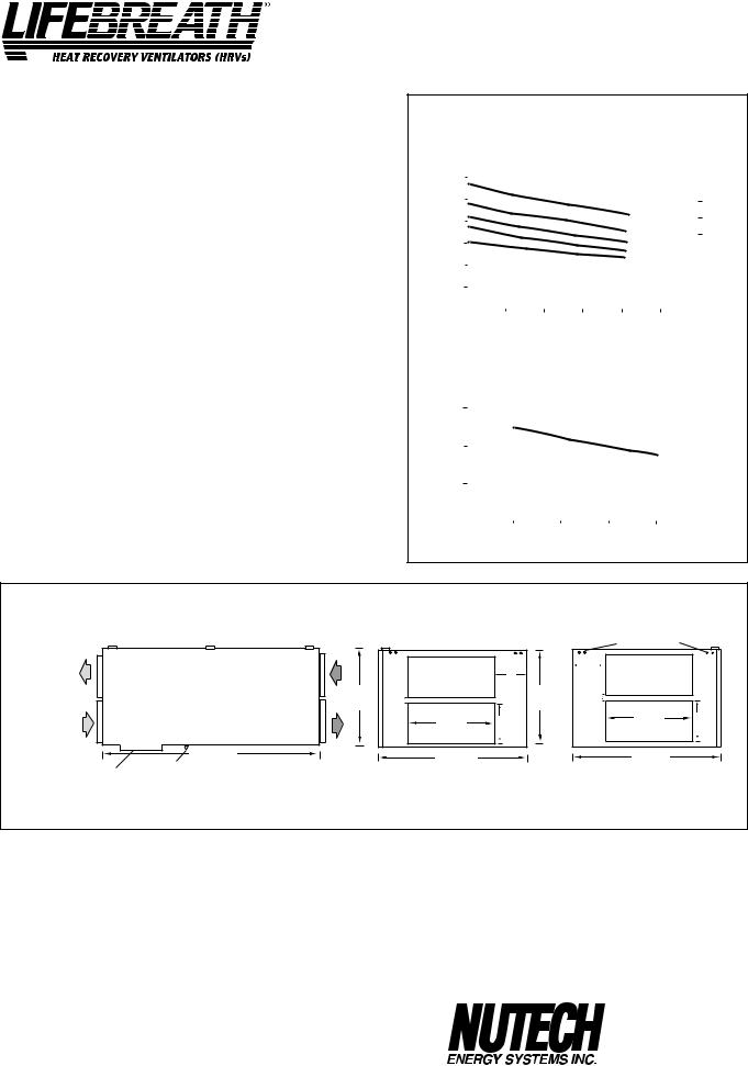
Model 500DCS
SPECIFICATIONS
CORES
Modular (4 section) patented aluminum heat recovery cores arranged for high efficiency crossflow ventilation.
MOTORS
Two PSC, 5 speed double shafted, 120 VAC, 3.15 Amps each (6.3 total on high speed). HP - 1/10, 1625 RPM. Watts - total on High Speed - 610.
FILTERS
Washable air filters in exhaust and supply air streams.
BLOWERS
Centrifugal type rated at 530 cfm (250 L/s) free air delivery. Each air stream has two centrifugal blowers driven by two PSC motors.
CONNECTION DUCT SIZES
Four - 14" x 8" (356 mm x 200 mm).
MOUNTING
Unit to be set on support brackets hung by threaded rod type apparatus (brackets and rods not included).
CASE
20 gauge prepainted galvanized steel (G60) for superior corrosion resistance. Insulated with foil faced insulation duct liner where required to prevent exterior condensation. Drain connection, One - 1/2" (12 mm) O.D. CONTROLS ControlAir 15
DEFROST
Supply bypass damper routes indoor air to defrost cores.
WEIGHT 178 lbs. (81 kg) SHIPPING WEIGHT 203 lbs. (92 kg)
PERFORMANCE
AIRFLOWS (Each Air Stream)
(CFM)L/s |
|
|
|
|
|
|
|
|
|
|
|
|
|
|
|
|
|
|
|
VAC |
190 |
(400) |
|
|
|
|
|
|
|
|
|
|
|
5 |
|
|
|
|
3.8 MED |
||
|
|
|
|
|
|
|
|
|
|
|
|
|
|
|
(AMPS)@ 120 |
|||||
|
282 |
(600) |
|
|
|
|
|
|
|
|
|
|
|
|
|
|
|
|
|
|
|
235 |
(500) |
|
|
|
|
|
|
|
|
|
|
|
SPEED |
|
|
6.3 HIGH |
|
||
|
|
|
|
|
|
|
|
|
|
|
|
|
|
|
|
|
|
|||
AIRFLOW |
42 |
(100) |
|
|
|
|
|
|
|
|
|
|
|
|
|
|
|
|
|
DRAWCURRENT |
|
|
|
|
|
|
|
|
|
|
|
4 |
|
|
|
|
3.1 LOW |
||||
|
143 |
(300) |
|
|
|
|
|
|
|
|
|
|
|
3 |
|
|
|
|
|
|
|
|
|
|
|
|
|
|
|
|
|
|
|
|
|
|
|
|
|||
|
|
|
|
|
|
|
|
|
|
|
|
2 |
|
|
|
|
|
|
||
|
|
|
|
|
|
|
|
|
|
|
|
|
|
|
|
|
|
|
|
|
|
94 |
(200) |
|
|
|
|
|
|
|
|
|
|
|
1 |
|
|
|
|
|
|
|
|
|
|
|
|
|
|
|
|
|
|
|
|
|
|
|
|
TOTAL |
||
|
|
|
|
|
|
|
|
|
|
|
|
|
|
|
|
|
|
|
|
|
|
|
|
|
|
|
|
|
|
|
|
|
|
|
|
|
|
|
|
|
|
|
|
25 |
(.1) |
50 |
(.2) |
75 |
(.3) |
100 |
(.4) |
125 |
(.5) |
|
|
|||||||
|
|
|
|
|
||||||||||||||||
|
|
|
EXTERNAL STATIC PRESSURE IN PASCALS (in. W.C.) |
|
||||||||||||||||
|
|
|
TEMPERATURE EFFECTIVENESS |
|
||||||||||||||||
|
EFFECTIVENESS |
100% |
|
|
|
|
|
|
|
|
|
|
|
|
|
|
|
|
|
|
|
|
|
|
|
|
|
|
|
|
|
|
|
|
|
|
|
|
|
||
|
|
|
|
|
|
|
|
|
|
|
|
|
|
|
|
|
|
|
|
|
|
|
90% |
|
|
|
|
|
|
|
|
|
|
|
|
|
|
|
|
|
|
|
|
|
|
|
|
|
|
|
|
|
|
|
|
|
|
|
|
|
|
|
|
|
80% |
|
|
|
|
|
|
|
|
|
|
|
|
|
|
|
|
|
|
|
|
|
|
|
|
|
|
|
|
|
|
|
|
|
|
|
|
|
|
|
|
|
|
|
|
|
|
|
|
|
|
|
|
|
|
|
|||||
|
|
|
|
|
|
|
|
|
|
NOTE: Exhaust |
Relative Humidity |
(RH) at 40% |
|
|
||||||
|
|
|
|
|
|
|
|
|
|
|
|
|
|
|
|
|
|
|
|
|
|
|
|
|
94 |
|
|
143 |
|
190 |
|
235 |
282 |
|
|||||||
|
|
|
|
(200) |
|
(300) |
|
(400) |
|
(500) |
(600) |
|
||||||||
AIRFLOW IN L/s (CFM)
|
|
|
|
inches (mm) |
|
|
||
EXHAUST AIR |
|
EXHAUST AIR |
|
|
|
|
|
|
|
FROM BUILDING |
|
|
|
MOUNTING POINTS |
|
||
TO OUTSIDE |
|
|
|
|
|
|||
|
|
|
|
|
|
|
|
|
|
|
|
|
|
|
|
150 mm |
|
|
|
|
|
|
150 mm |
|
(5 7/8") |
|
|
|
|
|
|
|
|
|
|
NOTE: |
|
|
|
|
(5 7/8") |
|
|
|
|
475 mm |
|
|
|
475 mm |
35 mm |
|
|
Service clearance |
|
32 mm |
|
|
|
|||
|
|
|
|
|
|
|||
|
DIMENSIONS 500DCS |
|
|
|
|
|
||
is 760 mm (30 in.) |
|
(18 3/4") |
(1 1/4") |
|
|
(18 3/4") |
(1 3/8") |
|
|
|
|
356 mm |
200 mm |
|
356 mm |
200 mm |
|
|
|
|
|
(14") |
||||
|
|
|
(14") |
|
(8") |
|
(8") |
|
|
|
|
|
|
|
|||
SUPPLY AIR |
1245 mm |
|
717 mm |
|
|
717 mm |
|
|
FROM OUTSIDE |
|
|
|
|
||||
DEFROST |
DRAIN CONNECTION (49") |
SUPPLY AIR |
(28 1/4 ") |
|
|
(28 1/4") |
|
|
FRONT VIEW |
TO BUILDING |
INTERIOR DUCT |
|
EXTERIOR DUCT |
||||
|
|
|||||||
|
|
|
||||||
|
|
|
CONNECTION SIDE |
|
CONNECTION SIDE |
|||
OPTIONS
99-104 Digital Electronic Timer - 20/40/60 min. (3 wire) 99-105 Programmable Ventilation Control
includes Programmable Time Clock, Dehumidistat and Air Sentry™
99-109 Air Sentry™ Air Quality Monitor designed to accept remotely mounted Control Pad
99-250 Ventilation Dehumidistat - Dehumidistat designed to accept remotely mounted Control Pad.
DATE: __________________________
All units conform to CSA and UL standards.
WARRANTY
Units carry a 15 year warranty on the heat recovery core and a 2 year replacement parts warranty.
|
511 McCormick Blvd. |
|
PROJECT: ________________________________________ |
London, Ontario N5W 4C8 |
|
Ph: (519) 457-1904 |
||
|
||
|
Fx: (519) 457-1676 |
|
MECHANICAL CONTRACTOR: ________________________________ |
Email: nutech@lifebreath.com |
|
Website: www.lifebreath.com |
||
6 |
TI-110-NE |
|
0011 |
||
|
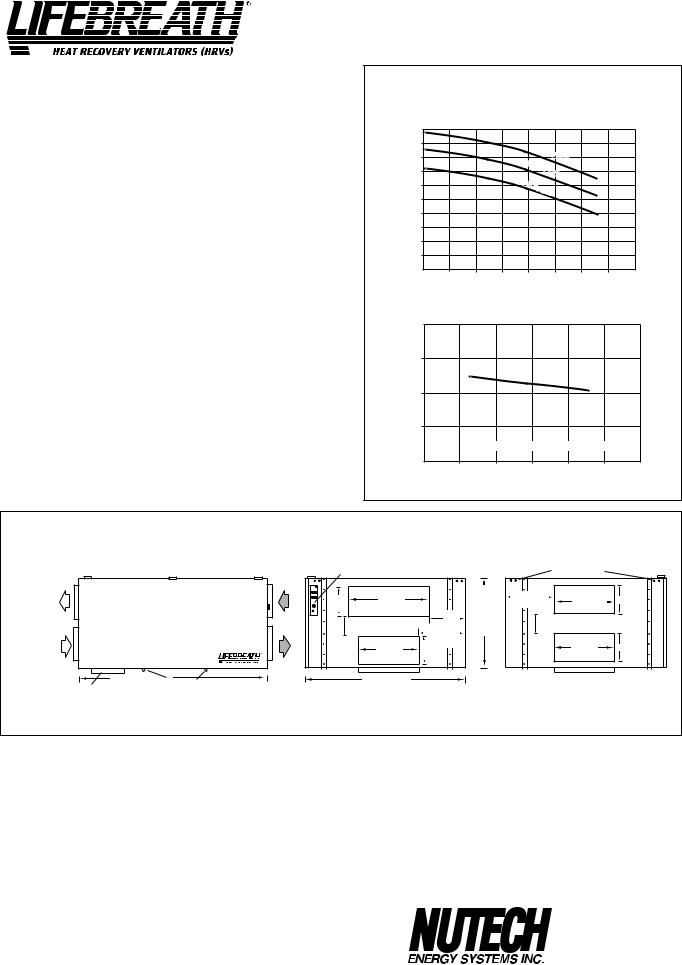
Model 850FD/DD
SPECIFICATIONS
CORES
Modular (6 section) patented aluminum heat recovery cores arranged for high efficiency crossflow ventilation.
MOTORS
Two PSC, 3 speed double shafted, 120 VAC, 3.95 Amps each (7.9 total on high speed). HP - 1/4, 1625 RPM. Watts - total on High Speed - 848.
FILTERS
Washable air filters in exhaust and supply air streams.
BLOWERS
Centrifugal type rated at 950 cfm (448 L/s) free air delivery. Each air stream has one double shafted motor driving two centrifugal blowers.
CONNECTION DUCT SIZES
Three - 20" x 8" (508 mm x 200 mm).
Stale air intake - 26" x 8" (660 mm x 200 mm). Model 850DD - additional 20" X 8" defrost port
MOUNTING
Unit to be set on support brackets hung by threaded rod type apparatus. (brackets and rods not provided).
CASE
20 gauge prepainted galvanized steel (G60) for superior corrosion resistance. Insulated with foil faced insulation where required to prevent exterior condensation. Drain connections, Two - 1/2" (12 mm) O.D.
CONTROLS
Illuminated power switch, 3 speed blower control, low voltage (24 VAC) terminals for connection of remote controls and defrost light indicating automatic operation.
DEFROST CONTROLS
Model 850FD - Interrupts supply air while exhaust air defrosts core. Model 850DD - Supply bypass routes indoor air to defrost core. WEIGHT 255 lbs. (116 kg) SHIPPING WEIGHT 280 lbs. (127 kg)
AIRFLOW L/s (CFM)
475 (1000)
425 (900)
378 (800)
329 (700)
282 (600)
235 (500)
190 (400)
143 (300)
94 (200)
42 (100)
PERFORMANCE
AIRFLOWS (Each Air Stream)
HIGH |
SPEED |
|||
MED |
|
|||
SPEED |
||||
LOW |
|
|||
SPEED |
||||
|
||||
25 (.1) |
50 (.2) |
75 (.3) |
100 (.4) |
125 (.5) |
150 (.6) |
175 (.7) |
EXTERNAL STATIC PRESSURE IN PASCALS (in. W.C.)
7.9HIGH
7.0MED
6.6LOW
TOTAL CURRENT DRAW (AMPS) @ 120 VAC
TEMPERATURE EFFECTIVENESS
EFFECTIVENESS |
90% |
|
|
|
80% |
|
70% |
NOTE: Exhaust Relative Humidity (RH) at 40%
235 |
282 |
329 |
378 |
425 |
(500) |
(600) |
(700) |
(800) |
(900) |
AIRFLOW IN L/s (CFM)
|
|
|
|
|
|
mm (inches) |
|
|
|
|
|
EXHAUST AIR |
|
|
EXHAUST AIR |
|
|
|
|
|
|
|
|
TO OUTSIDE |
|
|
FROM BUILDING |
CONTROLS |
|
|
|
|
MOUNTING POINTS |
|
|
|
|
|
|
|
|
|
|
|
|
||
|
|
|
|
200 mm |
660 mm |
|
|
263 mm |
508 mm |
200 mm |
|
|
|
|
|
850 |
(26") |
|
|
(10 3/8") |
(8") |
||
|
|
|
|
8") |
|
|
(20") |
||||
NOTE: |
|
|
DIMENSIONS( |
|
190 mm |
625 mm |
149 mm |
|
|||
Service clearance |
|
|
|
|
172 mm |
|
(7 1/2 ") |
|
|||
is 760 mm (30 in.) |
|
|
|
|
(6 3/4") |
|
263 mm |
(24 5/8") |
(5 7/8") |
|
|
|
|
|
|
|
|
|
|
||||
|
|
|
|
|
|
|
(10 3/8 ") |
|
|
508 mm |
|
|
|
|
|
|
508 mm |
200 mm |
|
|
200 mm |
||
|
|
|
|
|
|
|
(20") |
(8") |
|||
|
|
|
|
|
(20") |
|
|
||||
|
|
|
|
|
(8") |
|
|
|
|
||
|
|
|
|
|
|
|
|
|
|
|
|
SUPPLY AIR |
|
|
|
|
|
|
|
|
|
|
|
FROM OUTSIDE |
1188 mm |
|
|
|
1055 mm |
|
|
|
|
|
|
|
DRAIN CONNECTION |
SUPPLY AIR |
|
|
|
|
|
|
|||
DEFROST AIR |
(46 3/4") |
|
|
(41 1/2") |
|
|
|
|
|
||
DD MODELS ONLY |
FRONT VIEW |
TO BUILDING |
INTERIOR DUCT |
|
EXTERIOR DUCT |
||||||
|
|
||||||||||
|
|
|
|||||||||
|
|
|
|
|
CONNECTION SIDE |
|
|
CONNECTION SIDE |
|||
OPTIONS |
All units conform to CSA and UL standards |
|
99-101 |
Sixty Minute Timer |
|
|
|
WARRANTY |
99-130 |
Remote Wall Mount Dehumidistat Control |
All units carry a 15 year warranty on the heat recovery cores |
|
24 VAC only |
and a 2 year replacement parts warranty. |
DATE: __________________________
|
511 McCormick Blvd. |
|
PROJECT: ________________________________________ |
London, Ontario N5W 4C8 |
|
Ph: (519) 457-1904 |
||
|
||
|
Fx: (519) 457-1676 |
|
MECHANICAL CONTRACTOR: ________________________________ |
Email: nutech@lifebreath.com |
|
Website: www.lifebreath.com |
||
7 |
TI-111 |
|
|
0011 |
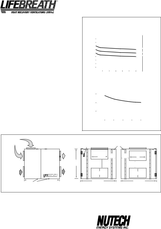
Model 700FD/DD
SPECIFICATIONS
CORES
Modular (2 section) patented aluminum heat recovery cores arranged for efficient cross-flow ventilation.
MOTORS
Two PSC, 3 speed single shafted, 120 VAC, 2.75 Amps each (5.5 total on high speed). HP - 1/10, 1625 RPM. Watts - total on high speed - 648.
FILTERS
Washable air filters in exhaust and supply air streams.
BLOWERS
Centrifugal type rated at 329 L/s (700 CFM) free air delivery. Each air stream has one single shafted motor driving a centrifugal blower.
CONNECTION DUCT SIZES
Four - 356 mm x 200 mm (14" x 8" ).
MOUNTING
Unit to be set on support brackets hung by threaded rod type apparatus (brackets and rods not provided).
CASE
20 gauge prepainted galvanized steel (G60) for superior corrosion resistance. Insulated with foil faced insulation where required to prevent exterior condensation. Drain connections; two - 12 mm (1/2") O.D.
CONTROLS
Illuminated power switch, 3 speed blower control, low voltage (24 VAC) terminals for connection of remote controls and defrost light indicating automatic operation.
DEFROST CONTROLS
MODEL 700 FD - Interrupts supply air while exhaust air defrosts core. MODEL 700DD - Supply bypass routes indoor air to defrost core. WEIGHT 64.4 kg (142 lbs.) SHIPPING WEIGHT 75.8 kg (167 lbs.)
|
|
|
MODPERFORMANCEL 700FD, 700DD |
|
|||||||||||||||||
|
|
|
|
|
|||||||||||||||||
|
|
|
AIRFLOWS (Each Air Stream) |
VAC |
|||||||||||||||||
|
|
|
|
|
|
|
|
|
|
|
|
|
|
|
|
|
|
|
|
|
|
(CFM)L/sAIRFLOW |
423 |
(900) |
|
|
|
|
|
|
|
|
|
|
|
|
|
|
|
|
|
|
@(AMPS)DRAWCURRENT120 |
|
|
|
|
|
|
|
|
|
|
|
|
|
|
|
|
|
|
||||
378 |
(800) |
|
|
|
|
|
|
|
|
|
|
|
|
|
|
|
|
|
|
||
|
|
|
|
|
|
|
|
|
|
|
|
|
|
|
|
|
|
|
|
||
|
329 |
(700) |
|
|
|
|
|
|
|
|
|
|
|
|
|
|
|
|
|
|
5.5 HIGH |
|
|
|
|
|
|
|
|
|
|
|
|
|
|
|
HIGH SPEED |
||||||
|
282 |
(600) |
|
|
|
|
|
|
|
|
|
|
|
|
|
|
5.0 MED |
||||
|
|
|
|
|
|
|
|
|
|
|
|
|
|
|
MED SPEED |
||||||
|
235 |
(500) |
|
|
|
|
|
|
|
|
|
|
|
|
|
|
4.7 LOW |
||||
|
|
|
|
|
|
|
|
|
|
|
|
|
|
|
|
|
|
|
|||
|
|
|
|
|
|
|
|
|
|
|
|
|
|
|
LOW SPEED |
||||||
|
190 |
(400) |
|
|
|
|
|
|
|
|
|
|
|
|
|
|
|
||||
|
|
|
|
|
|
|
|
|
|
|
|
|
|
|
|
|
|
|
|
||
|
143 |
(300) |
|
|
|
|
|
|
|
|
|
|
|
|
|
|
|
|
|
|
|
|
|
|
|
|
|
|
|
|
|
|
|
|
|
|
|
|
|
|
|
||
|
94 |
(200) |
|
|
|
|
|
|
|
|
|
|
|
|
|
|
|
|
|
|
|
|
|
|
|
|
|
|
|
|
|
|
|
|
|
|
|
|
|
|
|
||
|
42 |
(100) |
|
|
|
|
|
|
|
|
|
|
|
|
|
|
|
|
|
|
TOTAL |
|
|
|
|
|
|
|
|
|
|
|
|
|
|
|
|
|
|
|
|||
|
|
|
|
|
|
|
|
|
|
|
|
|
|
|
|
|
|
|
|
|
|
|
|
25 (.1) |
50 (.2) |
75 (.3) |
100 (.4) |
125 (.5) |
150 (.6) |
175 (.7) |
|
||||||||||||
|
|
|
EXTERNAL STATIC PRESSURE IN PASCALS (IN. W.C.) |
|
|||||||||||||||||
|
|
|
TEMPERATURE EFFECTIVENESS |
|
|||||||||||||||||
|
EFFECTIVENESS |
50% |
|
|
|
|
|
|
|
|
|
|
|
|
|
|
|
|
|
|
|
|
|
|
|
|
|
|
|
|
|
|
|
|
|
|
|
|
|
|
|
||
|
|
70% |
|
|
|
|
|
|
|
|
|
|
|
|
|
|
|
|
|
|
|
|
|
|
|
|
|
|
|
|
|
|
|
|
|
|
|
|
|
|
|
|
|
|
|
60% |
|
|
|
|
|
|
|
|
|
|
|
|
|
|
|
|
|
|
|
|
|
|
|
|
|
|
|
|
|
|
|
|
|
|
|
||||||
|
|
|
|
|
|
|
|
|
|
|
|
|
|
|
|
||||||
|
|
|
|
|
|
|
|
|
NOTE: Exhaust Relative Humidity (RH) at 40% |
|
|
||||||||||
|
|
|
|
|
|
|
|
|
|
|
|
|
|
|
|
|
|
|
|
|
|
|
|
143 |
|
|
190 |
|
235 |
282 |
|
329 |
|
|
|||||||||
|
|
(300) |
|
|
(400) |
|
(500) |
(600) |
|
(700) |
|
|
|||||||||
AIRFLOW IN L/s (CFM)
SUPPLY AIR |
|
|
|
|
|
|
mm (inches) |
|
|
|
FROM OUTSIDE |
DD MODEL ONLY |
|
|
|
|
|
||||
|
|
|
|
|
|
CONTROLS |
MOUNTING POINTS |
|
||
|
|
|
|
|
EXHAUST AIR |
|
|
|
||
|
|
|
|
|
|
|
|
|
|
|
|
|
|
|
|
TO OUTSIDE |
|
|
|
|
|
|
|
|
|
|
|
|
356 mm |
165 mm |
165 mm |
356 mm |
|
|
|
|
|
|
|
(14") |
(6 1/2") |
(6 1/2") |
(14") |
FD MODEL ONLY |
|
|
|
|
|
|
|
|
|
|
|
|
|
|
|
625 mm |
|
|
210 mm |
|
|
NOTE: |
|
|
|
DIMENSIONS 700 |
|
|
159 mm |
|||
|
|
|
|
(24 5/8 ") |
|
|
(8 1/4") |
|
||
Service clearance |
|
|
|
|
|
|
|
(6 1/4") |
||
|
|
|
|
|
|
|
|
|
||
is 760 mm (30 in.) |
|
|
|
|
|
|
|
|
|
|
from front |
|
|
|
|
|
|
|
|
|
|
access doors |
|
|
|
|
|
|
200 mm |
|
|
200 mm |
|
|
|
|
|
|
|
|
|
||
|
|
|
|
¤ |
|
|
(8") |
|
|
(8") |
EXHAUST AIR |
|
|
HEAT RECOVERY VENTILATORS (HRVs) |
SUPPLY AIR |
|
|
|
|
|
|
FROM BUILDING |
|
|
|
|
TO BUILDING |
|
730 mm |
|
|
730 mm |
|
DRAIN CONNECTION |
753 |
mm (29 5/8") |
|
|
(28 3/4") |
|
|
(28 3/4") |
|
|
FRONT VIEW |
|
|
DISCHARGE SIDE |
|
INLET SIDE |
||||
OPTIONS |
|
|
|
|
|
All units conform to CSA and UL standards. |
||||
99-101 Sixty Minute Timer
|
WARRANTY |
|
99-130 Remote Wall Mount Dehumidistat Control |
All units carry a 15 year warranty on the heat recovery cores |
|
24 VAC only |
and a 2 year replacement parts warranty. |
|
DATE: __________________________ |
|
|
|
|
511 McCormick Blvd. |
PROJECT: ________________________________________ |
|
London, Ontario N5W 4C8 |
|
Ph: (519) 457-1904 |
|
|
|
|
|
|
Fx: (519) 457-1676 |
MECHANICAL CONTRACTOR: ________________________________ |
Email: nutech@lifebreath.com |
|
Website: www.lifebreath.com |
||
8 |
|
TI-103 |
|
|
0011 |
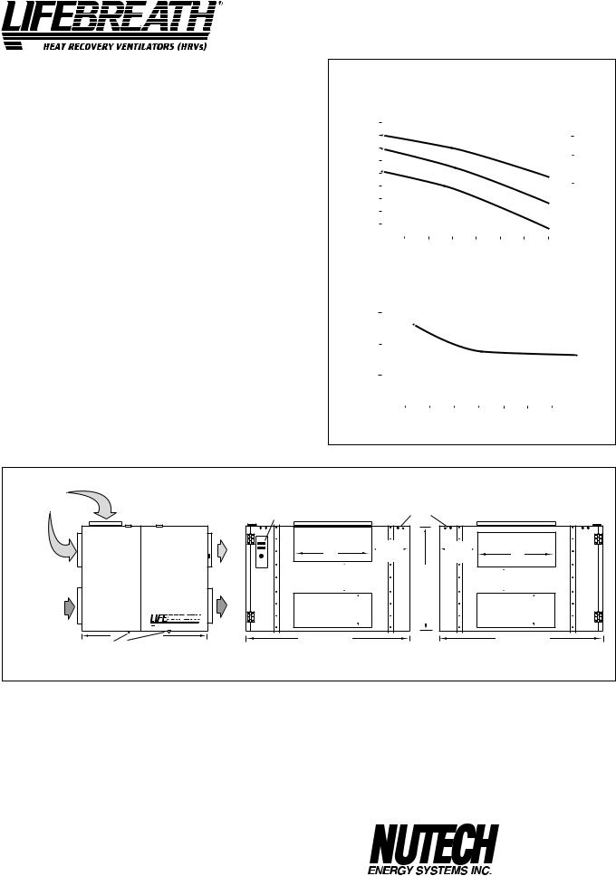
Model 1200FD/DD
SPECIFICATIONS
CORES
Modular (3 section) patented aluminum heat recovery cores arranged for efficient cross-flow ventilation.
MOTORS
Two PSC, 3 speed double shafted, 120 VAC, 4 Amps each (8.1 total on high speed). HP - 1/4, 1625 RPM. Watts - total on high speed - 972.
FILTERS
Washable air filters in exhaust and supply air streams.
BLOWERS
Centrifugal type rated at 1200 cfm (566 L/s) free air delivery. Each air stream has one double shafted motor driving a centrifugal blower.
CONNECTION DUCT SIZES
Four - 20" x 8" (508 mm x 200 mm).
MOUNTING
Unit to be set on support brackets hung by threaded rod type apparatus. (brackets and rod not provided).
CASE
20 gauge prepainted galvanized steel (G60) for superior corrosion resistance. Insulated with foil faced insulation where required to prevent exterior condensation. Drain connections; two - 1/2" (12 mm) O.D.
CONTROLS
Illuminated power switch, 3 speed blower control, low voltage (24 VAC) terminals for connection of remote controls and defrost light indicating automatic operation.
DEFROST CONTROLS
MODEL 1200FD - Interrupts supply air while exhaust air defrosts core. MODEL 1200DD - Supply bypass routes indoor air to defrost core. WEIGHT 191 lbs. (87 kg) SHIPPING WEIGHT 215 lbs. (98 kg)
|
|
|
PERFORMANCE |
|
|
|
|
||||||||||||||||||
|
|
|
|
AIRFLOWS (Each Air Stream) |
|
|
|
|
|||||||||||||||||
(CFM)L/s |
613 (1300) |
|
|
|
|
|
|
|
|
|
|
|
|
|
|
|
|
|
|
|
|
|
|
VAC |
|
|
|
|
|
|
|
|
|
|
|
|
|
|
|
|
|
|
|
|
|
|
|
||||
|
|
|
|
|
|
|
|
|
|
|
|
|
|
|
|
|
|
|
|
|
|
@(AMPS)120 |
|||
|
|
|
|
|
|
|
|
|
|
|
|
|
|
|
|
|
|
|
|
|
|
||||
566 (1200) |
|
|
|
|
|
|
|
|
|
|
|
|
|
|
|
|
|
|
|
|
8.1 HIGH |
||||
|
|
|
|
|
|
|
|
|
|
|
|
|
|
|
|
|
|
|
|
|
|
|
|||
|
|
518 (1100) |
|
|
|
|
|
|
|
|
|
|
|
|
|
|
|
|
|
|
|
|
7.8 MED |
|
|
|
|
|
|
|
|
|
|
|
|
|
|
|
|
|
HIGH |
SPEED |
|
|
|
|
|||||
|
|
472 (1000) |
|
|
|
|
|
|
|
|
|
|
|
|
|
|
|
|
|
||||||
|
|
|
|
|
|
|
|
|
|
|
|
|
|
|
|
|
|
|
|
|
|||||
AIRFLOW |
|
|
|
|
|
|
|
|
|
|
|
|
|
|
|
|
|
|
|
|
|
|
DRAWCURRENT |
||
423 (900) |
|
|
|
|
|
|
|
|
|
|
|
|
|
|
|
|
|
|
|
|
7.1 LOW |
||||
|
|
|
|
|
|
|
|
|
|
|
|
|
|
MED |
SPEED |
|
|
|
|
||||||
|
|
378 (800) |
|
|
|
|
|
|
|
|
|
|
|
|
|
|
|
|
|||||||
|
|
|
|
|
|
|
|
|
|
|
|
|
|
|
|
|
|
|
|
||||||
|
|
|
|
|
|
|
|
|
|
|
|
|
|
|
|
|
|
|
|
|
|
|
|||
|
|
329 (700) |
|
|
|
|
|
|
|
|
|
|
|
|
|
|
|
|
|
|
|
|
|
|
|
|
|
|
|
|
|
|
|
|
|
|
|
|
|
LOW |
SPEED |
|
|
|
|
|
|
||||
|
|
282 (600) |
|
|
|
|
|
|
|
|
|
|
|
|
|
|
|
|
|
|
|||||
|
|
|
|
|
|
|
|
|
|
|
|
|
|
|
|
|
|
|
|
|
|
|
|
|
|
|
|
235 (500) |
|
|
|
|
|
|
|
|
|
|
|
|
|
|
|
|
|
|
|
|
|
|
TOTAL |
|
|
|
|
|
|
|
|
|
|
|
|
|
|
|
|
|
|
|
|
|
|
|
|
||
|
|
|
|
|
|
|
|
|
|
|
|
|
|
|
|
|
|
|
|
|
|
|
|
|
|
|
|
25 (.1) |
50 (.2) |
75 (.3) |
100 (.4) |
125 (.5) |
150 (.6) |
175 (.7) |
|
|
|
||||||||||||||
|
|
|
|
|
|
||||||||||||||||||||
|
|
|
EXTERNAL STATIC PRESSURE IN PASCALS (in. W.C.) |
|
|
|
|
||||||||||||||||||
|
|
|
TEMPERATURE EFFECTIVENESS |
|
|
|
|
||||||||||||||||||
|
|
|
|
|
|
|
|
|
|
|
|
|
|
|
|
|
|
|
|
|
|
|
|
|
|
|
|
EFFECTIVENESS 50% |
|
|
|
|
|
|
|
|
|
|
|
|
|
|
|
|
|
|
|
|
|
|
|
|
|
70% |
|
|
|
|
|
|
|
|
|
|
|
|
|
|
|
|
|
|
|
|
|
|
|
|
|
|
|
|
|
|
|
|
|
|
|
|
|
|
|
|
|
|
|
|
|
|
|
|
|
|
|
60% |
|
|
|
|
|
|
|
|
|
|
|
|
|
|
|
|
|
|
|
|
|
|
|
|
|
|
|
|
|
|
|
|
|
|
|
|
|
|
|
|
|
|
|
|
|
|
|
|
|
|
|
|
|
|
|
|
|
|
|
|
|
|
|
|
|
|
|||||||||
|
|
|
|
|
|
|
|
|
|
|
|
|
|
|
|
|
|||||||||
|
|
|
|
|
|
|
|
|
NOTE: |
Exhaust Relative Humidity (RH) at 40% |
|
|
|
||||||||||||
|
|
|
|
|
|
|
|
|
|
|
|
|
|
|
|
|
|
|
|
|
|
|
|
|
|
|
|
235 |
282 |
329 |
378 |
423 |
472 |
518 |
566 |
|
|||||||||||||||
|
|
(500) |
(600) |
(700) |
(800) |
(900) |
(1000) |
(1100) |
(1200) |
|
|||||||||||||||
AIRFLOW IN L/s (CFM)
SUPPLY AIR |
|
|
|
|
|
mm (inches) |
|
|
|
|
|
|
|
|
|
|
|
|
|
FROM OUTSIDE |
DD MODEL ONLY |
|
|
|
MOUNTING POINTS |
|
|||
|
|
|
EXHAUST AIR |
CONTROLS |
|
|
|||
|
|
|
|
|
|
|
|||
|
|
|
TO OUTSIDE |
|
|
|
|
|
|
|
|
|
DIMENSIONS 1200 |
508 mm |
263 mm |
263 mm |
508 mm |
||
|
|
|
(20") |
(20") |
|||||
FD MODEL ONLY |
|
|
(10 3/8") |
(10 3/8") |
|||||
NOTE: |
|
|
|
|
|
|
172 mm |
625 mm |
149 mm |
|
|
|
|
|
|
(24 5/8 ") |
|||
Service clearance |
|
|
|
|
|
|
(6 3/4") |
(5 7/8") |
|
is 760 mm (30 in.) |
|
|
|
|
|
|
|
|
|
from front |
|
|
|
|
|
|
|
|
|
access doors |
|
|
|
|
|
|
200 mm |
|
200 mm |
|
|
|
|
|
|
|
|
||
|
|
|
|
¤ |
|
|
(8") |
|
(8") |
EXHAUST AIR |
|
|
HEAT RECOVERY VENTILATORS (HRVs) |
|
1055 mm |
|
|
|
|
FROM BUILDING |
|
|
|
|
|
|
1055 mm |
||
|
DRAIN CONNECTION |
759 |
mm (29 7/8") |
SUPPLY AIR |
(41 1/2") |
|
|
(41 1/2") |
|
|
FRONT VIEW |
TO BUILDING |
DISCHARGE SIDE |
|
INLET SIDE |
||||
|
|
|
|||||||
OPTIONS |
|
|
|
|
|
|
|
|
|
All units conform to CSA and UL standards
99-101 Sixty Minute Remote Timer
|
WARRANTY |
|
99-130 Remote Wall Mount Dehumidistat Control |
All units carry a 15 year warranty on the heat recovery cores |
|
24 VAC only |
and a 2 year replacement parts warranty. |
|
|
|
|
DATE: __________________________ |
|
|
|
|
511 McCormick Blvd. |
PROJECT: ________________________________________ |
|
London, Ontario N5W 4C8 |
|
Ph: (519) 457-1904 |
|
|
|
|
|
|
Fx: (519) 457-1676 |
MECHANICAL CONTRACTOR: ________________________________ |
Email: nutech@lifebreath.com |
|
Website: www.lifebreath.com |
||
9 |
TI-120 |
|
0011 |
||
|
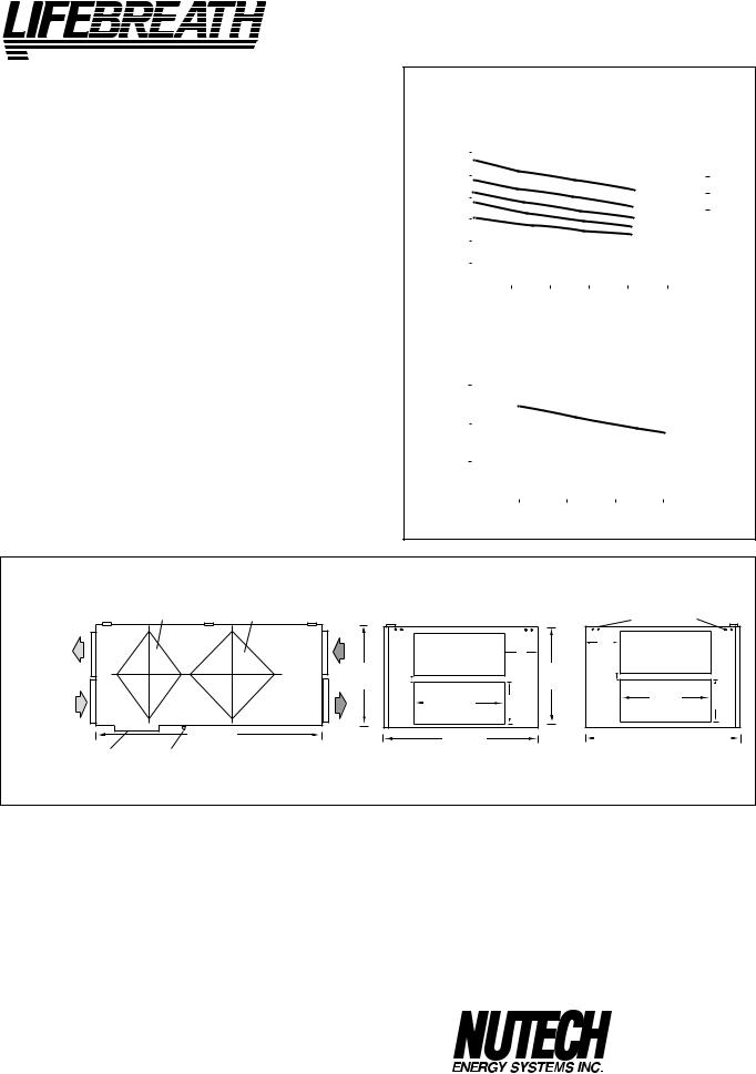
®
CLEA N • FRES H • AIR
SPECIFICATIONS
LATENT RECOVERY (MOISTURE) TRANSFER CORES
Modular (4 section) 2- Enthalpic, 2 Aluminum arranged for high efficiency crossflow ventilation.
MOTORS - Two PSC, 5 speed double shafted, 120 VAC, 3.15 Amps each (6.3 total on high speed). HP - 1/10, 1625 RPM. Watts - total on High Speed - 610.
FILTERS - Washable air filters in exhaust and supply air streams. BLOWERS - Centrifugal type rated at 530 cfm (250 L/s) free air delivery. Each air stream has two centrifugal blowers driven by two PSC motors.
CONNECTION DUCT SIZES Four - 14" x 8" (356 mm x 200 mm). MOUNTING - Unit to be set on support brackets hung by threaded rod type apparatus (brackets and rods not included).
DEFROST - Damper defrost system.
CASE - 20 gauge prepainted galvanized steel (G60) for superior corrosion resistance. Insulated with foil faced insulation duct liner where required to prevent exterior condensation. Drain connection, One - 1/2" (12 mm) O.D.
CONTROLS - ControlAir 15
WEIGHT 178 lbs. (81 kg) SHIPPING WEIGHT 203 lbs. (92 kg)
Model 500ERV
PERFORMANCE
AIRFLOWS (Each Air Stream)
(CFM)L/s |
|
|
|
|
|
|
|
|
|
|
|
|
|
|
|
|
|
|
|
VAC |
190 |
(400) |
|
|
|
|
|
|
|
|
|
|
|
5 |
|
|
|
|
3.8 MED |
||
|
|
|
|
|
|
|
|
|
|
|
|
|
|
|
(AMPS)@ 120 |
|||||
|
282 |
(600) |
|
|
|
|
|
|
|
|
|
|
|
|
|
|
|
|
|
|
|
235 |
(500) |
|
|
|
|
|
|
|
|
|
|
|
SPEED |
|
|
6.3 HIGH |
|
||
|
|
|
|
|
|
|
|
|
|
|
|
|
|
|
|
|
|
|||
AIRFLOW |
42 |
(100) |
|
|
|
|
|
|
|
|
|
|
|
|
|
|
|
|
|
DRAWCURRENT |
|
|
|
|
|
|
|
|
|
|
|
4 |
|
|
|
|
3.1 LOW |
||||
|
143 |
(300) |
|
|
|
|
|
|
|
|
|
|
|
3 |
|
|
|
|
|
|
|
|
|
|
|
|
|
|
|
|
|
|
|
|
|
|
|
|
|||
|
|
|
|
|
|
|
|
|
|
|
|
2 |
|
|
|
|
|
|
||
|
|
|
|
|
|
|
|
|
|
|
|
|
|
|
|
|
|
|
|
|
|
94 |
(200) |
|
|
|
|
|
|
|
|
|
|
|
1 |
|
|
|
|
|
|
|
|
|
|
|
|
|
|
|
|
|
|
|
|
|
|
|
|
TOTAL |
||
|
|
|
|
|
|
|
|
|
|
|
|
|
|
|
|
|
|
|
|
|
|
|
|
|
|
|
|
|
|
|
|
|
|
|
|
|
|
|
|
|
|
|
|
25 |
(.1) |
50 |
(.2) |
75 |
(.3) |
100 |
(.4) |
125 |
(.5) |
|
|
|||||||
|
|
|
|
|
||||||||||||||||
|
|
|
EXTERNAL STATIC PRESSURE IN PASCALS (in. W.C.) |
|
||||||||||||||||
|
|
|
TEMPERATURE EFFECTIVENESS |
|
||||||||||||||||
|
EFFECTIVENESS |
100% |
|
|
|
|
|
|
|
|
|
|
|
|
|
|
|
|
|
|
|
|
|
|
|
|
|
|
|
|
|
|
|
|
|
|
|
|
|
||
|
|
|
|
|
|
|
|
|
|
|
|
|
|
|
|
|
|
|
|
|
|
|
90% |
|
|
|
|
|
|
|
|
|
|
|
|
|
|
|
|
|
|
|
|
|
|
|
|
|
|
|
|
|
|
|
|
|
|
|
|
|
|
|
|
|
80% |
|
|
|
|
|
|
|
|
|
|
|
|
|
|
|
|
|
|
|
|
|
|
|
|
|
|
|
|
|
|
|
|
|
|
|
|
|
|
|
|
|
|
|
|
|
|
|
|
|
|
|
|
|
|
|
|||||
|
|
|
|
|
|
|
|
|
|
NOTE: Exhaust |
Relative Humidity |
(RH) at 40% |
|
|
||||||
|
|
|
|
|
|
|
|
|
|
|
|
|
|
|
|
|
|
|
|
|
|
|
|
|
94 |
|
|
143 |
|
190 |
|
235 |
282 |
|
|||||||
|
|
|
|
(200) |
|
(300) |
|
(400) |
|
(500) |
(600) |
|
||||||||
AIRFLOW IN L/s (CFM)
|
|
|
|
|
inches (mm) |
|
|
||
EXHAUST AIR |
ENTHALPIC CORE |
ALUMINUM CORE |
EXHAUST AIR |
|
|
|
|
|
|
FROM BUILDING |
|
|
MOUNTING POINTS |
|
|||||
TO OUTSIDE |
|
|
|
||||||
|
|
|
|
|
|
|
|
|
|
|
|
|
|
|
|
|
|
5 7/8" |
|
|
|
|
|
|
|
5 7/8" |
|
(150 mm) |
|
|
|
|
|
|
|
|
|
|
|
NOTE: |
|
|
|
|
|
(150 mm) |
|
|
|
|
|
|
18 3/4" |
|
|
18 3/4" |
1 3/8" |
|
|
Service clearance |
|
|
|
1/4" |
|
|
|||
|
|
|
|
|
|
|
|||
|
|
DIMENSIONS 500ERV1 |
|
|
|
|
|||
is 30 in. (760 mm) |
|
|
|
(475 mm) |
(32 mm) |
|
(475 mm) |
(35 mm) |
|
|
|
|
|
|
14" |
8" |
|
14" |
8" |
|
|
|
|
|
|
(356 mm) |
(200 mm) |
||
|
|
|
|
|
(356 mm) |
(200 mm) |
|
||
|
|
|
|
|
|
|
|
||
SUPPLY AIR |
|
49" |
|
|
28 1/4 " |
|
|
28 1/4" |
|
FROM OUTSIDE |
|
|
|
|
|
|
|||
|
(1245 mm) |
|
SUPPLY AIR |
(717 mm) |
|
|
(717 mm) |
|
|
DEFROST DRAIN CONNECTION |
|
|
TO BUILDING |
INTERIOR DUCT |
|
EXTERIOR DUCT |
|||
|
FRONT VIEW |
|
|
||||||
|
|
|
|
||||||
|
|
|
|
|
CONNECTION SIDE |
|
CONNECTION SIDE |
||
OPTIONS |
|
|
|
|
All units conform to CSA and UL standards. |
|
|||
99-104 Digital Electronic Timer - 20/40/60 min. (3 wire) 99-105 Programmable Ventilation Control includes
Programmable Time Clock, Dehumidistat and Air Sentry™
99-109 Air Sentry™ Air Quality Monitor designed to accept remotely mounted Control Pad
WARRANTY
Units carry a 5 year warranty on the energy recovery cores, a 15 year warranty on aluminum cores and a 2 year replacement parts warranty.
ERVs are not recommended for regions where the design temperature is below 25°F (-4°C)
DATE: __________________________
|
511 McCormick Blvd. |
|
PROJECT: ________________________________________ |
London, Ontario N5W 4C8 |
|
Ph: (519) 457-1904 |
||
|
||
|
Fx: (519) 457-1676 |
|
MECHANICAL CONTRACTOR: ________________________________ |
Email: nutech@lifebreath.com |
|
Website: www.lifebreath.com |
10 |
TI-130 |
|
0105 |
||
|
 Loading...