


663 660 SECOND STACK OPTION
WARNING:
Read and follow all directions for each step to insure proper assembly of this product.
USER’S GUIDE
CLASS H |
1 |
Version: 663101 |
PART # 7050101 |
|
Revision: 07/31/01 |
REV. C |
|
|
TABLE OF CONTENTS
Safety Statement |
.............2 |
General Notes.................. |
3 |
Tools Required................ |
3 |
Parts list.......................... |
4 |
Assembly Instructions..... |
4-16 |
General Maintenance....... |
17 |
Warranty Statement.......... |
18 |
Product Services.............. |
19 |
Insert-Registration Card |
|
IMPORTANT SAFETY INFORMATION
THERE IS A RISK ASSUMED BY INDIVIDUALS WHO USE THIS TYPE OF
EQUIPMENT. TO MINIMIZE RISK FOLLOW THESE RULES!
1.Before using, read all the warnings and instructions on the use of this machine. Use only for intended exercise. DO NOT modify the machine.
2.Obtain a medical exam before beginning any exercise program.
3.Keep body and clothing free of all moving objects.
4.Inspect the machine before use. DO NOT use it if it appears damaged. DO NOT attempt to fix a broken or
jammed machine. Notify your authorized ParaBody dealer before use and have repairs made by an authorized service technician.
5. Be certain that weight pin is completely inserted. Use only the pin provided by the manufacturer. If unsure, call your authorized ParaBody dealer.
6. Never pin the weights or prop plate into an elevated position. DO NOT use the machine if found in this condition. DO NOT attempt to fix. Notify your authorized ParaBody dealer.
7. Inspect cables and their connections before using machine. Pay particular attention to the cable ends. DO NOT attempt to fix. Notify your authorized ParaBody dealer before use and have repairs made by an authorized service technician.
8.Make sure all spring loaded pull pins are fully engaged in the adjustment position and fully tighten thumbscrew before use.
9.Children must not be allowed near this machine. Supervise teenagers.
.
NOTE: In a continual effort to improve our products, specifications are subject to change © 2001 LifeFitness, a division of Brunswick Corporation. All rights reserved. ParaBody is a trademark of Brunswick Corporation
www.parabody.com
2
IMPORTANT NOTES
Please note:
*Thank you for purchasing the ParaBody 663 660 Second Stack Option. Please read these instructions thoroughly and keep them for future reference.
*This product must be assembled on a flat, level surface to assure its proper function. DO NOT securely tighten any frame connections until the entire frame has been assembled, unless otherwise stated.
Tools Required for Assembly
*Rubber mallet or hammer
*3/4” wrench
*9/16” wrench
*Ratchet with 3/4” and 9/16” sockets
*7/32” Allen wrench
*Adjustable wrench
*Tape measure
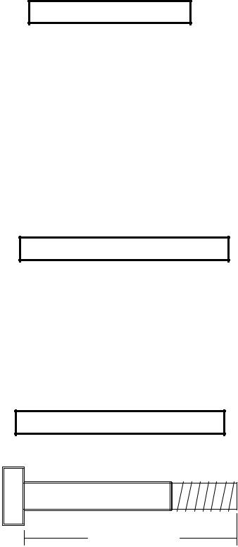
Bolt Length Ruler
NOTE: BOLT LENGTH IS MEASURED FROM THE UNDERSIDE OF THE HEAD OF THE BOLT.
BOLT LENGTH
BOLT LENGTH RULER:
|
1/2 |
|
1/2 |
|
1/2 |
|
1/2 |
|
1/2 |
|
|
1/2 |
|
|||||||||||
0 |
|
|
1 |
|
|
2 |
|
|
3 |
|
|
4 |
|
|
5 |
|
6 |
|||||||
|
|
|
|
|
|
|
|
|
|
|
|
|
|
|
|
|
|
|
|
|
|
|
|
|
3
PARTS LIST
KEY |
PART # |
DESCRIPTION |
QTY |
|
KEY |
PART # |
DESCRIPTION |
QTY |
1 |
6523401 |
GUIDEROD |
2 |
|
10 |
6978101 |
WEIGHT STACK LABEL |
1 |
2 |
7095701 |
WEIGHT STACK SHAFT |
1 |
|
11 |
3102909 |
3/8 X 1” BOLT |
1 |
3 |
7012102 |
WEIGHT STACK SPACER |
2 |
|
12 |
6480301 |
3/8” FLANGE SPACER |
2 |
4 |
6957302 |
HEAD PLATE |
1 |
|
13 |
3102922 |
3/8 X 2-3/4” BOLT |
1 |
5 |
7032302 |
PRESS-STACK CABLE |
1 |
|
14 |
3102802 |
3/8” LOCK NUT |
1 |
6 |
3116101 |
4-1/2” PULLEY |
1 |
|
15 |
3102503 |
3/4” WASHER |
2 |
7 |
6972201 |
WEIGHT STACK PIN |
1 |
|
16 |
6939202 |
WEIGHT PLATE |
15 |
8 |
3108002 |
WEIGHT STACK CUSHION |
2 |
|
17 |
6382301 |
WEIGHT PLATE BUSHING 10 CT. |
3 |
9 |
3117401 |
CAP PLUG |
4 |
|
18 |
3221702 |
E-RING |
1 |
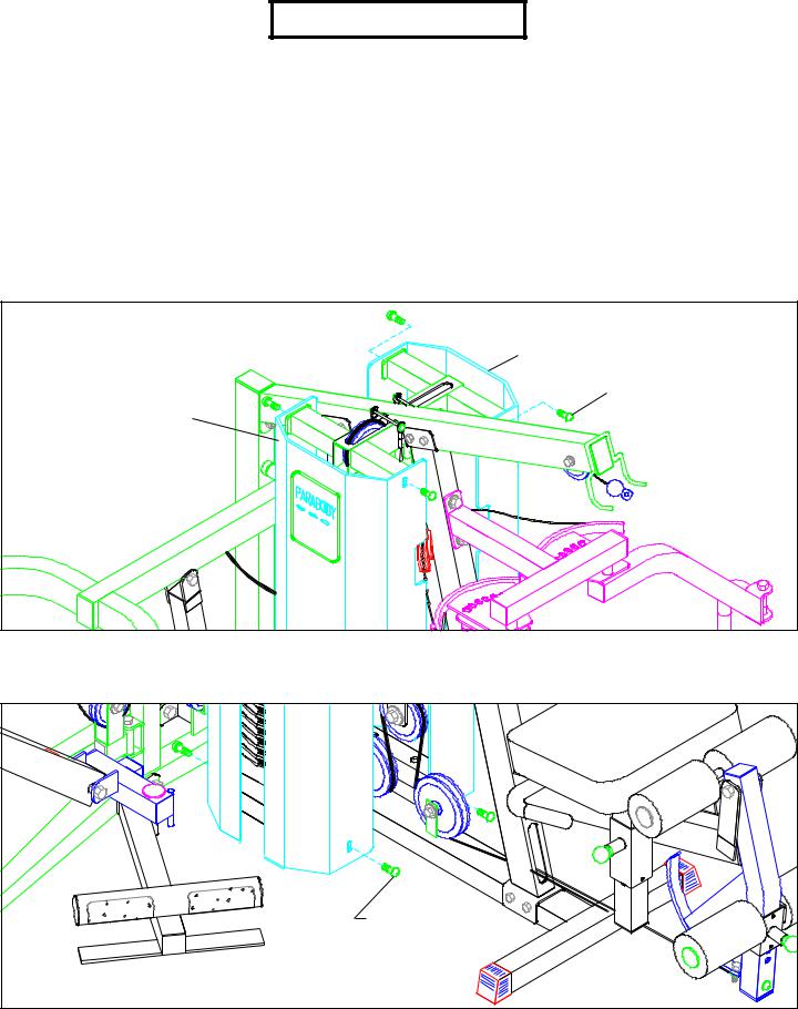
FIGURE 1 |
|
|
REAR SHROUD |
|
3/8” X 1” BUTTON |
FRONT SHROUD |
HEAD CAP SCREW |
|
STEP 1
• REMOVE the four 3/8” X 1” BUTTON HEAD CAP SCREWS from the top of the front SHROUD & rear SHROUD. See FIGURE 1.
3/8” X 1” BUTTON |
HEAD CAP SCREW |
FIGURE 2 |
STEP 2
•REMOVE the four 3/8” X 1” BUTTON HEAD CAP SCREWS from the bottom of the front SHROUD & rear SHROUD. Remove the SHROUDS from the 660101 HOME GYM. See FIGURE 2.
4
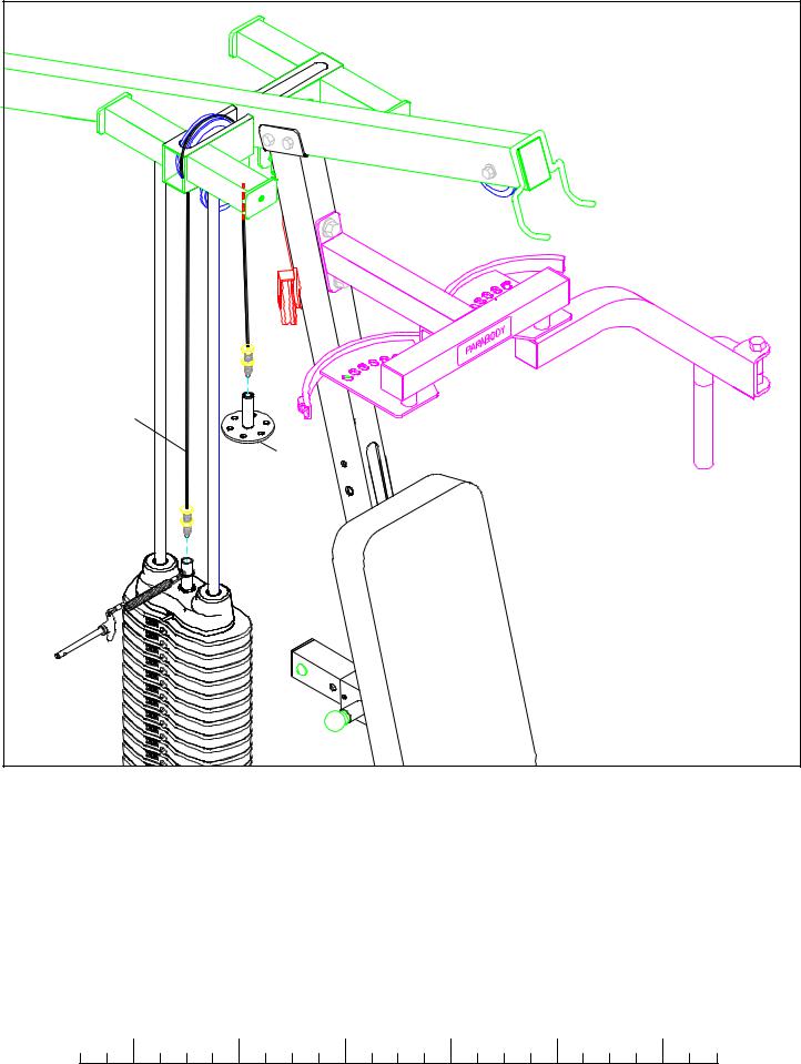
HEAD |
|
PLATE |
D-RING |
CABLE |
|
(7041801) |
|
|
FIGURE 3 |
STEP 3
•Unscrew the threaded ends of the HEAD PLATE CABLE from the WEIGHT STACK SHAFT & the D-RING and remove HEAD PLATE CABLE. The HEAD PLATE CABLE will be used later. See FIGURE 3. (NOTE: Remove pulleys for ease of removal.)
|
1/2 |
|
1/2 |
|
1/2 |
|
1/2 |
|
1/2 |
|
|
1/2 |
0 |
1 |
2 |
3 |
4 |
5 |
6 |
||||||
5
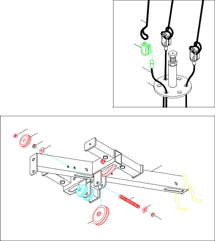
STEP 4 |
FIGURE 4 |
|
• Remove the PRESS CABLE (67249) from the KEYHOLE CLEVIS |
ELASTIC |
|
and ELASTIC CORD. (NOTE: The LATorLEGEXTCABLE can |
||
CORD |
||
bemovedoveroneholeontheD-RINGsotheKEYHOLECLEVIS |
||
|
||
are evenly spaced .) |
|
|
• Discard the KEYHOLE CLEVIS and ELASTIC CORD. |
KEYHOLE |
|
|
||
|
CLEVIS |
PRESSCABLE |
(67249) |
D-RING |
FIGURE 5 |
3/8” LOCK NUT |
2”PULLEY |
3/8” HEX NUT |
3/8” WASHER |
TOP BOOM |
3/8” THREADED ROD |
3/8” WASHER |
3/8” LOCK NUT |
3-1/2” PULLEY |
STEP 5
•Remove one 3-1/2” PULLEY, one 3/8” THREADED SHAFT, two 3/8” WASHERS, one 2” PULLEY (two if the 435104 is installed), one 3/8” HEX NUT and two 3/8” LOCK NUTS from the bracket on the TOP BOOM. See FIGURE 5.
•Discard the 3-1/2” PULLEY and the 3/8” THREADED SHAFT.
•(NOTE: If the 100101 LEG PRESS OPTION is installed proceed to STEP 6 otherwise proceed to STEP 7.)
6
 Loading...