


 Loading...
OWNER’S MANUAL
M2394D
M2794D
Please read this manual carefully before operating your set.
Retain it for future reference.
Record model number and serial number of the set. See the label attached on the back cover and quote this information to your dealer when you require service.
Trade Mark of the DVB Digital Video
Broadcasting Project (1991 to 1996)
ID Number(s): 5743 : M2394D
5744 : M2794D
PREPARATION
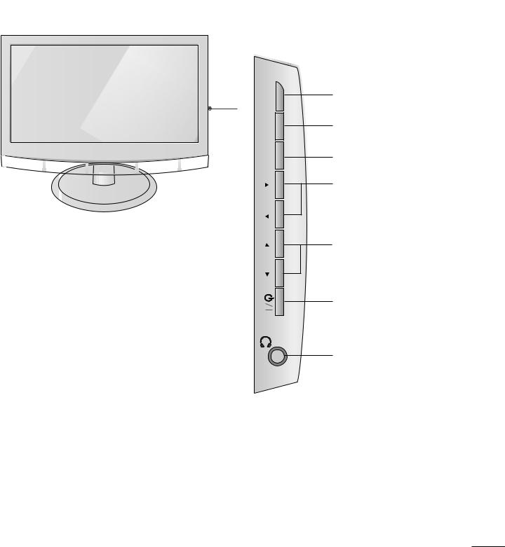
FRONT PANEL CONTROLS
■This is a simplified representation of the front panel. The image shown may be somewhat different from your set.
VOL OK MENU INPUT
PR
INPUT
Button
MENU
Button
OK
Button
VOLUME
Buttons
PROGRAMME
Buttons
Power
Button
Headphone
Button
1
PREPARATION
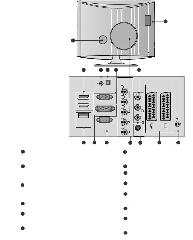
BACK PANEL INFORMATION
■This is a simplified representation of the back panel. The image shown may be somewhat different from your set.
1
2
3 |
4 |
5 |
6 |
|
|
|
7 |
|
|
|
|
|
|
COMPONENT |
AV |
3 |
|
|
|
|
AUDIO IN |
|
|
IN |
|
|
|
|
|
|
(RGB/DVI) |
OPTICAL |
|
Y |
|
|
AV 1 |
|
AV 2 |
|
|
|
|
|
|
||||
|
AUDIO OUT |
|
|
VIDEO |
|
(MONO)VIDEO |
|
|
|
|
1 |
|
|
PB |
|
|
|
||
|
|
|
|
|
|
|
|
||
HDMI |
RGB |
|
|
|
|
|
|
|
|
|
2 |
|
|
PR |
|
|
|
|
|
|
|
|
|
|
|
|
L |
|
|
|
|
|
|
|
|
|
AUDIO |
|
ANTENNA |
|
|
|
|
L |
|
|
|
IN |
|
|
|
|
|
|
|
|
|
||
SERVICE |
|
|
|
|
|
R |
|
|
|
ONLY |
RS- |
IN |
|
|
AUDIO |
|
|
|
|
|
R |
|
|
|
|
||||
|
(CONTROL |
|
|
|
|
|
|
||
|
|
|
|
|
|
|
|
||
|
|
|
|
|
|
S-VIDEO |
|
|
|
|
|
10 |
|
|
11 |
|
12 |
13 |
14 |
1 |
|
|
|
7 |
|
|
|
|
|
International Association) Card Slot
(This feature is not available in all countries.)
2Power Cord Socket
This set operates on AC power. The voltage is indicated on the Specifications page. Never attempt to operate the set on DC power.
3HDMI Input
Connect a HDMI signal to HDMI IN.
Or DVI (VIDEO) signal to HDMI IN with DVI to HDMI cable.
4RGB/DVI Audio Input Connect the audio from a PC.
5Optical Digital Audio Out
Connect digital audio from various types of eguipment
6RGB INPUT (PC)
Connect the output from a PC.
Connect audio/video output from an external device to these jacks.
8 SERVICE ONLY PORT
9DVI-D Input
Connect the output from a PC.
10RS-232C IN (CONTROL & SERVICE) PORT Connect to the RS-232C port on a PC.
11Component Input
Connect a component video/audio device to these jacks.
12S-Video Input
Connect S-Video out from an S-VIDEO device.
13Euro Scart Socket (AV1/AV2)
Connect scart socket input or output from an external device to these jacks.
14Antenna Input
Connect over-the-air signals to this jack.
2
PREPARATION
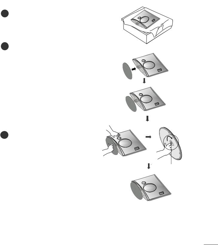
STAND INSTALLATION
■ The image shown may be somewhat different from your set.
Carefully place the product screen side down on a 1 cushioned surface that will protect product and
screen from damage.
2 Insert the stand base into the product
3 Attach the monitor to the Stand Base by turning the screw to the right.
* Turn the screw by using the screw handle
Screw
3
PREPARATION
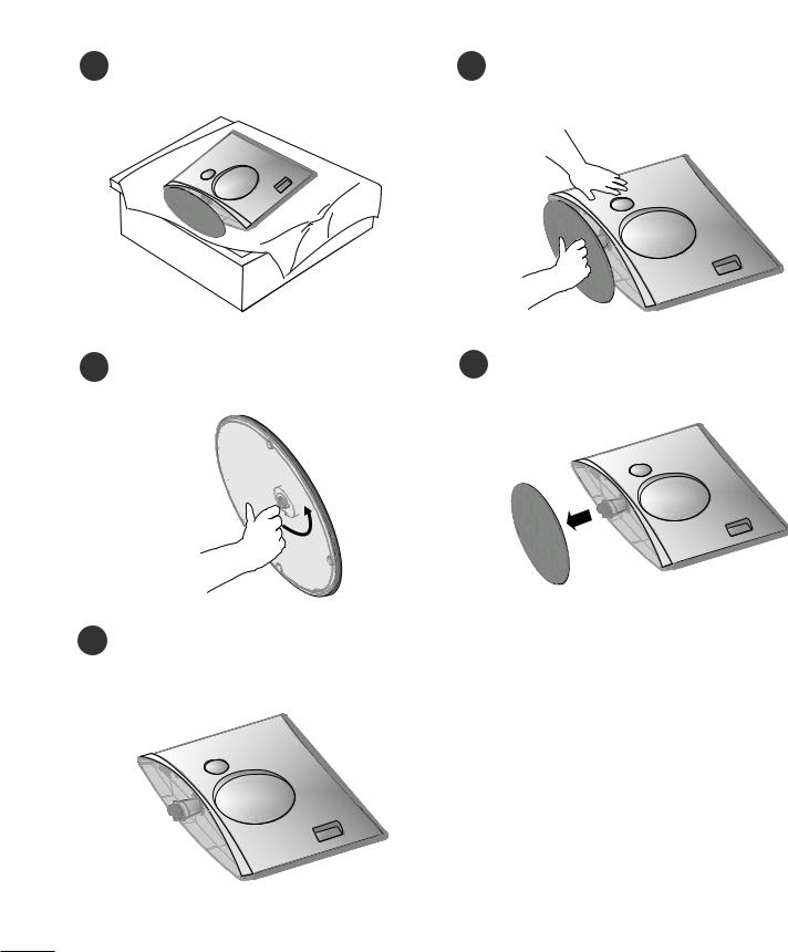
DETACHING STAND
■ The image shown may be somewhat different from your set.
1Place the set screen side down on a cushion or soft cloth.
2Detach the monitor to the Stand Base by turning the screw to the left.
3 Turn the screw by using the screw handle |
4 Pull the stand base. |
5
4
PREPARATION
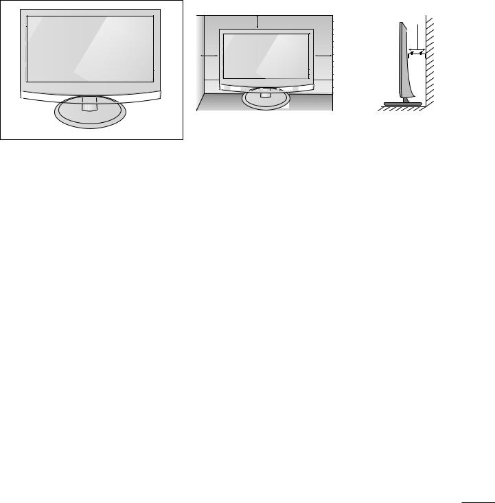
DESKTOP PEDESTAL INSTALLATION
For proper ventilation, allow a clearance of 4 inches on each side and from the wall.
4 inches
4 inches |
4 inches |
4 inches |
5
PREPARATION
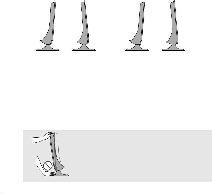
POSITIONING YOUR DISPLAY
■ The image shown may be somewhat different from your set.
Adjust the position of the panel in various ways for maximum comfort.
• Tilt range
<M2394D> |
|
|
<M2794D> |
|
|
|
|
|
|
-6° ~ -2° |
12°~ 18° |
|
-5° ~ -2° |
7°~ 13° |
|
|
|
|
|
LOCATION
Position your set so that no bright light or sunlight falls directly onto the screen. Care should be taken not to expose the set to any unnecessary vibration, moisture, dust or heat. Also, ensure that the set is placed in a position to allow a free flow of air. Do not cover the ventilation openings on the back cover.
If you intend to mount the set to a wall, attach VESA standard mounting interface (optional parts) to the back of the set.
When you install the set using the wall mounting bracket (optional parts), attach it carefully so it will not drop.
Warning:
When adjusting the angle of the screen,do not put your finger(s)in between the head of the monitor and the stand body.You can hurt your finger(s).
6
PREPARATION
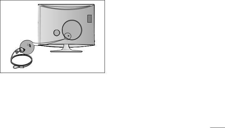
KENSINGTON SECURITY SYSTEM
-The product is equipped with a Kensington Security System connector on the back panel. Connect the Kensington Security System cable as shown below.
-For detailed installation and use of the Kensington Security System, refer to the user’s guide provided with the Kensington Security System.
For further information, contact http://www.kensington.com, the internet homepage of the Kensington company. Kensington sells security systems for expensive electronic equipment such as notebook PCs and LCD projectors.
NOTE
- The Kensington Security System is an optional accessory.
NOTES
a.If the product feels cold to the touch, there may be a small “flicker” when it is turned on. This is normal, there is nothing wrong with product.
b.Some minute dot defects may be visible on the screen, appearing as tiny red, green, or blue spots. However, they have no adverse effect on the monitor's performance.
c.Avoid touching the LCD screen or holding your finger(s) against it for long periods of time.
Doing so may produce some temporary distortion effects on the screen.
7

PREPARATION
■ To prevent equipment damage, never plug in any power cords until you have finished connecting all equipment.
ANTENNA CONNECTION
■For optimum picture quality, adjust antenna direction.
■An antenna cable and converter are not supplied.
Wall
Antenna
Socket
Outdoor
Antenna
(VHF, UHF)
Antenna
PCMCIA EJECT
CARD SLOT
HDM
Multi-family Dwellings/Apartments
(Connect to wall antenna socket) ANTENNA
IN
RF Coaxial Wire (75 ohm)
Single-family Dwellings /Houses
(Connect to wall jack for outdoor antenna)
PCMCIA EJECT
CARD SLOT
HDM
UHF
ANTENNA
IN
Signal Amplifier
VHF
■In poor signal areas, to get better picture quality, install a signal amplifier to the antenna as shown above.
■If signal needs to be split for two TVs, use an antenna signal splitter for connection.
8
EXTERNAL EQUIPMENT SETUP
■To prevent the equipment damage, never plug in any power cords until you have finished connecting all equipment.
■The image shown may be somewhat different from your set.
HD RECEIVER SETUP
When connecting with a component cable
1Connect the SET-TOP outputs to the COMPONENT IN VIDEO sockets (Y PB PR) on the set.
COMPO-
Press the INPUT button to select Component.
Signal |
Component |
HDMI |
|
|
|
|
|
No |
480i/576i |
Yes |
|
480p/576p |
Yes |
Yes |
720p/1080i |
Yes |
Yes |
1080p |
Yes |
Yes |
|
|
|
|
|
|
COMPONENT
IN
Y
PB
PR |
VIDEO |
|
|
L |
|
R |
AUDIO |
|
1
2
9
EXTERNAL EQUIPMENT SETUP
When connecting with a HDMI
of the digital set-top box to the
1
1
HDMI
2
1
When connecting with a HDMI to DVI cable
1Connect the digital set-top box to HDMI IN jack on the set.
digital set-top box to on the set.
Turn on the digital set-top box. (Refer to the owner’s manual for the digital set-top box.)
 1 HDMI
2
1
AUDIO IN (RGB/DVI)
2
L |
AUDIO |
R |
DVI OUTPUT
10
EXTERNAL EQUIPMENT SETUP
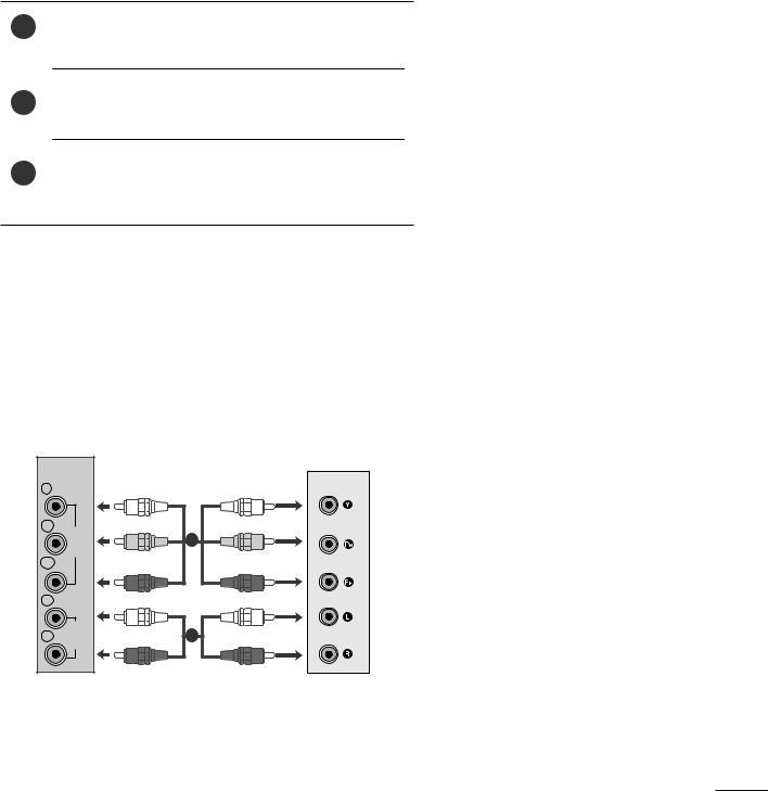
DVD SETUP
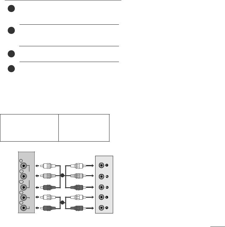
When connecting with a component cable
Connect the video output sockets (Y PB PR) of the DVD to 1 the COMPONENT IN IDEO sockets (Y PB PR) of the
set.
PONENT
IN AUDIO sockets of |
set. |
Press the INPUT |
select Component. |
Press the PLAY button |
the DVD. |
The DVD playback |
appears on the screen. |
|
|
Component Input ports
To get better picture quality, connect a DVD player to the component input ports as shown below.
Component ports on the set |
Y |
PB |
PR |
|
|
|
|
Video output ports
on DVD player
Y |
PB |
PR |
|
Y |
B-Y |
R-Y |
|
Y |
Cb |
Cr |
|
Y |
Pb |
Pr |
|
|
|
|
|
|
|
|
COMPONENT
IN
Y
PB
PR |
VIDEO |
|
|
L |
|
R |
AUDIO |
|
1
2
11
EXTERNAL EQUIPMENT SETUP
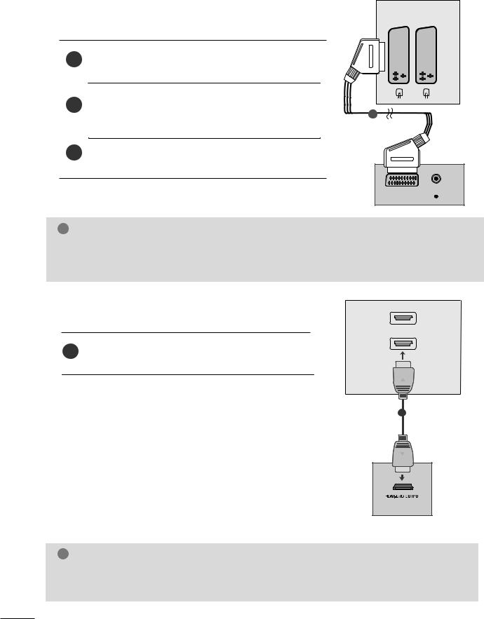
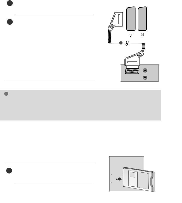
When connecting with a Euro Scart
Connect the Euro scart socket of the DVD to the Euro scart
1socket of the set.
AV 1 |
AV 2 |
|||||||||||||
|
|
|
|
|
|
|
|
|
|
|
|
|
|
|
1
source.
Press the PLAY button on the DVD.
The DVD playback picture appears on the screen.
(R)
(L) AUDIO AUDIO/ 
! NOTE
GSignal type RGB, i.e. the signals red, green and blue can only be selected for the Euro received. These signals are transmitted, for example, by a paid TV decoder, game machine
GPlease use shielded scart cable.
and the AV 1 can be photo CD unit, etc.
When connecting HDMI cable
of the DVD to the
1
1
HDMI
2
1
! NOTE
G Set can receive the video and audio signal simultaneously by using a HDMI cable.
G If the DVD player does not support Auto HDMI, you need to set the DVD output resolution appropriately.
12
EXTERNAL EQUIPMENT SETUP
VCR SETUP
■To avoid picture noise (interference), leave an adequate distance between the VCR and set.
■Typically a still picture is shown on the VCR. If a user uses 4:3 picture format for a long time, an afterimage may remain on the sides of the screen.
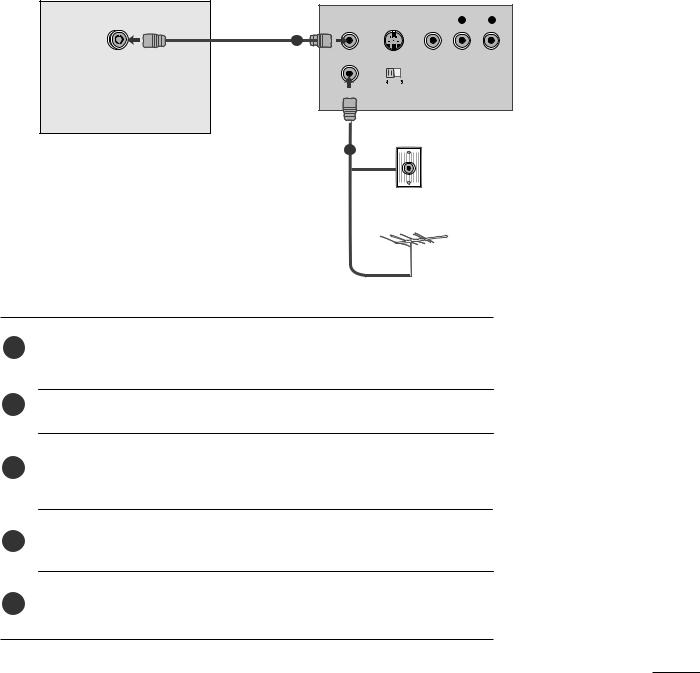
When connecting with an antenna
ANT OUT S-VIDEO VIDEO |
L |
R |
ANTENNA IN |
1 |
OUTPUT
IN SWITCH
Wall Jack
2
Antenna
1 |
to the aerial socket of the set. |
|
2Connect the aerial cable to the RF aerial in socket of the VCR.
3Store the VCR channel on a desired programme number using the ‘Manual programme tuning’ section.
4Select the programme number where the VCR channel is stored.
5 Press the PLAY button on the VCR.
13
EXTERNAL EQUIPMENT SETUP
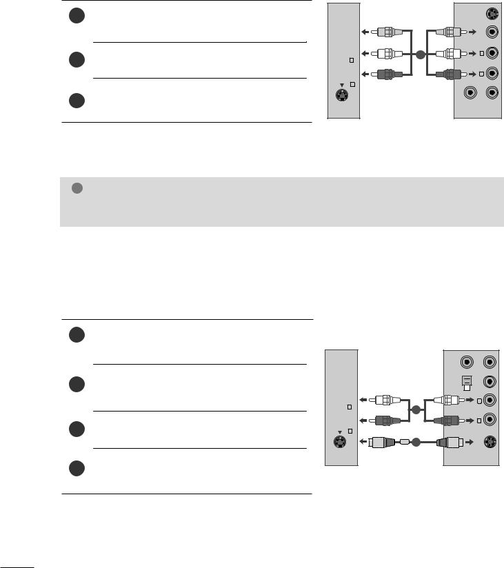
When connecting with a RCA cable
1Connect the audio/video out sockets of the VCR to AUDIO/VIDEO in sockets of the set.
Press the PLAY button on the VCR.
The VCR playback picture appears on the screen.
AV-IN 3
R AUDIO L (MONO) VIDEO
S-VIDEO
|
VIDEO VIDEO-S |
1 |
|
|
R |
OUT ANT |
IN ANT |
! NOTE
G If you have a mono VCR, connect the audio cable from the VCR to the AUDIO L/MONO jack of the set.
When connecting with an S-Video cable
1Connect the S-Video socket of the VCR to the S- VIDEO socket of the set.
the
Press the INPUT button to select AV3.
Press the PLAY button on the VCR.
The VCR playback picture appears on the screen.
AV-IN 3
R AUDIO L (MONO) VIDEO
S-VIDEO
1
2
OUT ANT |
IN ANT |
3 4 OUTPUT SWITCH |
VIDEO |
|
L |
|
R |
|
VIDEO-S |
14
EXTERNAL EQUIPMENT SETUP
When connecting with a Euro Scart
|
|
|
|
|
|
|
|
1 |
Connect the Euro scart socket of the VCR to the Euro |
|
|
|
AV 1 AV 2 |
||
scart socket of the set. |
|
|
|
||||
|
|
|
|
|
|
||
|
PLAY button on the VCR. |
|
|
|
|
|
|
|
|
|
|
|
|
||
|
|
|
|
|
|
||
|
|
|
|
|
|
||
|
|
|
|
|
|
||
|
|
|
|
|
|
||
|
outputs an AV switching signal via the Scart |
|
|
|
|
|
|
|
|
|
|
|
|
||
|
lead, the set will auto switch to AV 1 mode on start of |
|
|
|
|
|
|
|
|
|
|
|
|
||
|
playback, but if you want to keep on watching in TV mode, |
|
|
|
|
|
|
|
press the D / E or NUMBER buttons. |
|
|
|
|
|
|
|
|
|
|
|
|
||
|
If connected to AV2 Euro scart socket, select AV2 input |
|
|
|
|
|
|
|
1 |
|
|
|
|
||
|
source. |
|
|
|
|
||
|
|
|
|
|
|
||
Otherwise press the INPUT button on the remote control handset to select AV 1. The VCR playback picture appears on the screen.
You can also record programmes received by the set on video tape.
(R)
(L) AUDIO
AUDIO/
VIDEO
! NOTE
GSignal type RGB, i.e. the signals red, green and blue can only be selected for the Euro scart and the AV 1 can be received. These signals are transmitted, for example, by a paid TV decoder, game machine or photo CD unit, etc.
GPlease use shielded scart cable.
INSERTION OF CI MODULE
-To view the scrambled (paid) services in digital TV mode.
-This feature is not available in all countries.
1 |
(Personal Computer |
|
CARD SLOT |
||
|
||
|
of set as shown. |
|
|
For further information, see p. 39. |
|
|
|
PCMCIA
TV
15
EXTERNAL EQUIPMENT SETUP
PC SETUP
This product provides Plug and Play capability, meaning that the PC adjusts automatically to the set's settings.
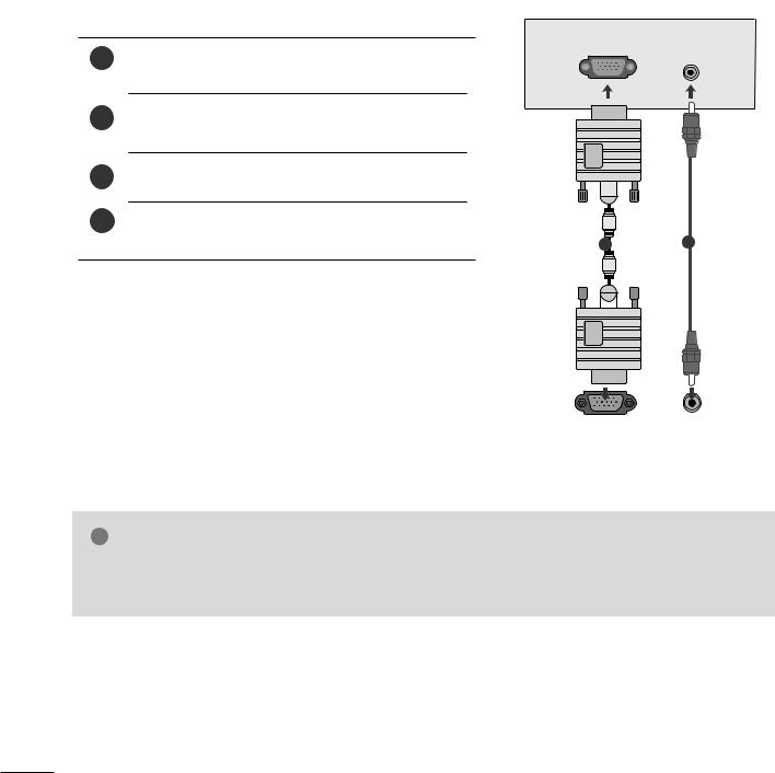
When connecting with a D-sub 15 pin cable
1Connect the signal cable from the monitor output socket of the PERSONAL COMPUTER to the PC input socket of the set.
the AUDIO IN
Press the INPUT button to select RGB.
Switch on the PC, and the PC screen appears on the set.
RGB IN (PC) |
AUDIO IN |
|
(RGB/DVI) |
12
|
|
|
|
|
|
|
|
|
|
|
|
|
|
|
|
|
|
|
|
|
|
|
|
|
|
|
|
|
|
|
|
|
|
|
|
|
|
|
|
|
|
|
|
|
RGB OUTPUT |
AUDIO |
|||||||
|
|
|
||||||
|
|
|
|
|
|
|
|
|
! NOTE
G User must use shielded signal interface cables (D sub 15 pin cable, DVI cable) with ferrite cores to maintain standard compliance for the product.
16
EXTERNAL EQUIPMENT SETUP
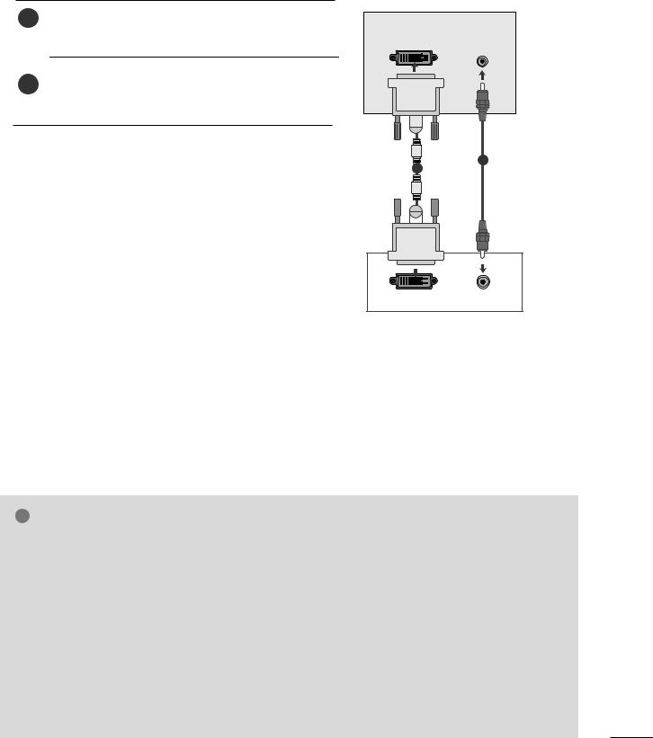
When connecting with a DVI cable
1Connect the DVI output of the PC to the DVI-D IN jack on the set.
PC to the AUDIO
DVI-D |
AUDIO IN |
|
(RGB/DVI) |
2
1
|
|
|
|
|
|
|
|
|
|
|
|
|
|
|
|
|
|
|
|
|
|
|
|
|
|
|
|
|
|
|
|
|
|
|
|
|
|
|
|
|
|
|
|
|
|
|
|
|
|
|
|
AUDIO |
||
|
DVI OUTPUT |
|
||||||||
|
|
|
|
|
||||||
|
|
|
|
|
|
|
|
|
|
|
! NOTE
G If the set is cold, there may be a small “flicker” when the set is switched on. This is normal, there is nothing wrong with the set.
G If possible, use the 1920x1080 @ 60 Hz video mode to obtain the best image quality for your LCD monitor If used with other resolutions, some scaled or processed pictures may appear on the screen. The set has been preadjusted to the mode 1920x1080 @ 60 Hz.
G Some dot defects may appear on the screen, like Red, Green or Blue spots. However, this will have no impact or effect on the monitor performance.
G Do not press the screen with your finger for a long time as this may produce some temporary distortion effects on screen.
G Avoid keeping a fixed image on the set’s screen for prolonged periods of time. The fixed image may become permanently imprinted on the screen; use a screen when possible.
17

BACK COVER FOR WIRE ARRANGEMENT
Tie cables together with a cable tie as shown in the illustration.
R |
18

EXTERNAL EQUIPMENT SETUP
RGB/DVI[PC]
Resolution |
Horizontal |
Vertical |
|
Frequency(kHz) |
Frequency(Hz) |
||
|
|||
|
|
|
|
720x400 |
31.468 |
70 |
|
640x480 |
31.469 |
60 |
|
37.500 |
75 |
||
|
|||
800x600 |
37.879 |
60 |
|
46.875 |
75 |
||
|
|||
1024x768 |
48.363 |
60 |
|
60.123 |
75 |
||
|
|||
1152x864 |
67.500 |
75 |
|
1280x1024 |
63.981 |
60 |
|
79.976 |
75 |
||
|
|||
1680x1050 |
64.674 |
60 |
|
65.290 |
60 |
||
|
|||
1600x1200 |
75.000 |
60 |
|
1920x1080 |
66.587 |
60 |
HDMI[DTV] supported mode
Resolution |
Horizontal |
Vertical |
|
Frequency(kHz) |
Frequency(Hz) |
||
|
|||
|
31.47 |
60 |
|
720x480/60p |
|||
31.5 |
60 |
||
|
|||
720x576/50p |
31.25 |
50 |
|
1280x720/50p |
37.5 |
50 |
|
1280x720/60p |
44.96 |
60 |
|
45 |
60 |
||
|
|||
1920x1080/60i |
33.72 |
60 |
|
33.75 |
60 |
||
|
|||
1920x1080/50i |
28.125 |
50 |
|
1920x1080/24p |
26.97 |
24 |
|
27 |
24 |
||
|
|||
1920x1080/30p |
33.72 |
30 |
|
33.75 |
30 |
||
|
|||
1920x1080/50p |
56.25 |
50 |
|
1920x1080/60p |
67.43 |
60 |
|
67.5 |
60 |
||
|
|||
|
|
|
19
EXTERNAL EQUIPMENT SETUP
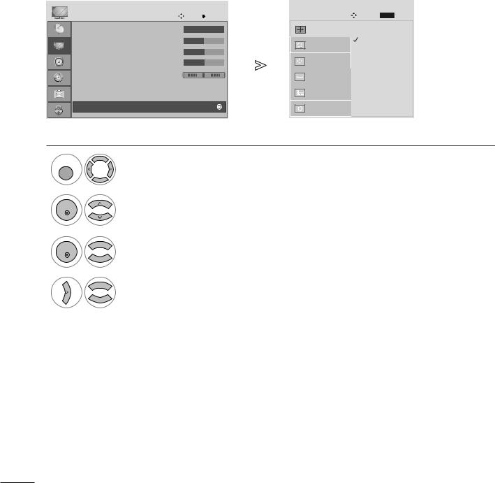
SCREEN SETUP FOR PC MODE
Screen Reset
Returns Position, Size and Phase to the default factory settings.
This function works in the following mode: RGB[PC].
PICTURE |
|
Move |
OK |
|
SCREEN |
Move |
BACK |
Prev. |
D |
|
|
|
|
|
|
|
|
• Contrast |
: 100 |
|
|
|
Resolution |
|
|
|
• Brightness |
: 50 |
|
|
|
Auto Config. |
|
|
|
• Sharpness |
: 50 |
|
|
|
|
|
|
|
|
|
|
|
|
|
|
||
• Colour |
: 50 |
|
|
|
Position |
|
To Set |
|
• Tint |
: 0 |
R |
|
G |
Size |
|
|
|
• Advanced Control |
|
|
|
|
|
|
||
|
|
|
|
|
|
|
||
• Picture Reset |
|
|
|
|
Phase |
|
|
|
|
|
|
|
|
|
|
|
|
Screen |
|
|
|
|
Reset |
G |
|
|
|
|
|
|
|
|
|
|
|
MENU
Select PICTURE.
OK |
Select SCREEN. |
|
|
OK |
Select Reset. |
|
|
OK |
Select Yes. |
|
|
OK |
Run Reset. |
•Press the MENU or EXIT button to close the menu window.
•Press the BACK button to move to the previous menu screen.
20
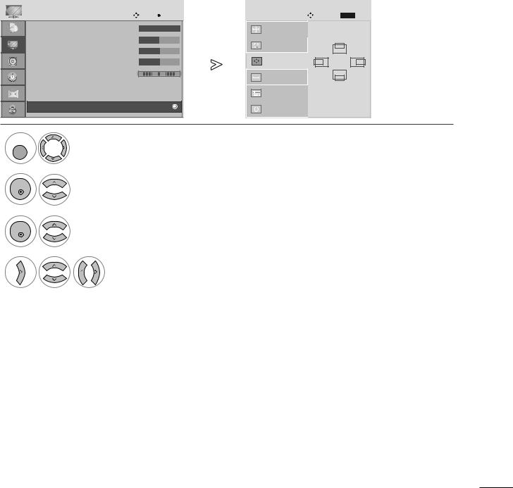
EXTERNAL EQUIPMENT SETUP
Adjustment for screen Position, Size, Phase
If the picture is not clear after auto adjustment and especially if characters are still shaky, adjust the picture phase manually.
This function works in the following mode: RGB[PC].
PICTURE |
|
Move |
OK |
|
SCREEN |
|
Move |
BACK |
Prev. |
D |
|
|
|
|
|
|
|
|
|
• Contrast |
: 100 |
|
|
|
Resolution |
|
|
|
|
• Brightness |
: 50 |
|
|
|
Auto Config. |
|
|
|
|
• Sharpness |
: 50 |
|
|
|
|
|
|
|
|
|
|
|
|
|
|
D |
|
||
• Colour |
: 50 |
|
|
|
Position |
|
F |
|
|
|
|
|
G |
G |
|
||||
|
|
|
|
|
|
|
|
E |
|
• Tint |
: 0 |
R |
|
G |
Size |
|
|
|
|
• Advanced Control |
|
|
|
|
|
|
|
||
|
|
|
|
|
|
|
|
||
• Picture Reset |
|
|
|
|
Phase |
|
|
|
|
|
|
|
|
|
|
|
|
|
|
|
|
|
|
|
Reset |
|
|
|
|
MENU |
|
|
|
|
|
|
|
|
|
OK |
Select SCREEN. |
|
|
OK |
Select Position, Size or Phase. |
|
|
|
Make appropriate adjustments. |
•Press the MENU or EXIT button to close the menu window.
•Press the BACK button to move to the previous menu screen.
21
EXTERNAL EQUIPMENT SETUP
Selecting Resolution
To view a normal picture, match the resolution of RGB mode and selection of PC mode. This function works in the following mode: RGB[PC] mode.
PICTURE |
|
Move |
OK |
|
SCREEN |
|
Move |
BACK |
Prev. |
|
|
|
|
|
|
|
|||
D |
|
|
|
|
|
|
|
|
|
• Contrast |
: 100 |
|
|
|
Resolution |
G |
1400 x 1050 |
|
|
• Brightness |
: 50 |
|
|
|
Auto Config. |
|
1680 x 1050 |
|
|
• Sharpness |
: 50 |
|
|
|
|
|
|
|
|
|
|
|
|
|
|
|
|
||
• Colour |
: 50 |
|
|
|
Position |
|
|
|
|
• Tint |
: 0 |
R |
|
G |
Size |
|
|
|
|
|
|
|
|
|
|
|
|
|
|
• Advanced Control |
|
|
|
|
|
|
|
|
|
• Picture Reset |
|
|
|
|
Phase |
|
|
|
|
|
|
|
|
|
|
|
|
|
|
Screen |
|
|
|
|
Reset |
|
|
|
|
MENU
|
Select PICTURE. |
OK |
Select SCREEN. |
|
|
OK |
Select Resolution. |
|
Select the desired resolution.
•Press the MENU or EXIT button to close the menu window.
•Press the BACK button to move to the previous menu screen.
22
EXTERNAL EQUIPMENT SETUP
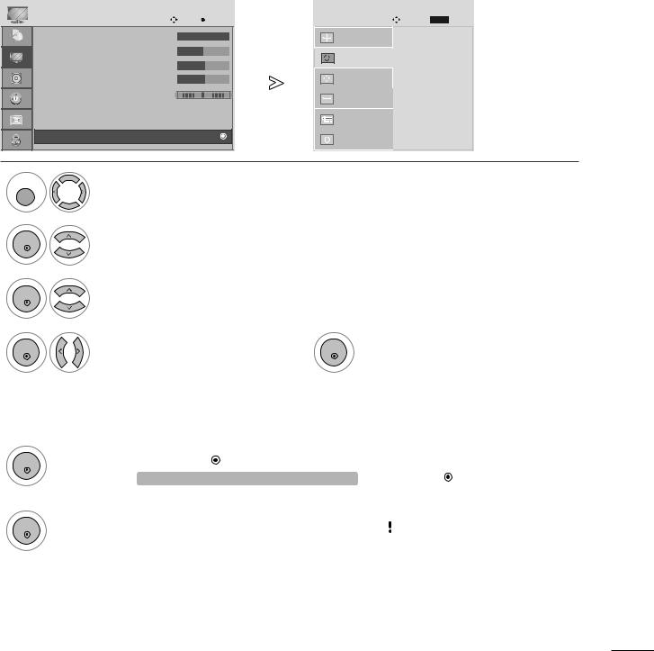
Auto Configure (RGB [PC] mode only)
Automatically adjusts picture position and minimizes image instability. After adjustment, if the image is still not correct, your set is functioning properly but needs further adjustment.
Auto configure
This function is for automatic adjustment of the screen position, clock, and phase The displayed image will be unstable for a few seconds while the auto configuration is in progress.
1. Using OSD |
|
|
|
|
|
|
|
|
PICTURE |
|
Move |
OK |
|
SCREEN |
Move |
BACK |
Prev. |
D |
|
|
|
|
|
|
|
|
• Contrast |
: 100 |
|
|
|
Resolution |
|
|
|
• Brightness |
: 50 |
|
|
|
Auto Config. |
G |
|
|
|
|
|
|
|
|
|
||
• Sharpness |
: 50 |
|
|
|
|
|
|
|
• Colour |
: 50 |
|
|
|
Position |
|
To Set |
|
|
|
|
|
|
|
|
|
|
• Tint |
: 0 |
R |
|
G |
Size |
|
|
|
• Advanced Control |
|
|
|
|
|
|
||
|
|
|
|
|
|
|
||
• Picture Reset |
|
|
|
|
Phase |
|
|
|
|
|
|
|
|
|
|
|
|
Screen |
|
|
|
|
Reset |
|
|
|
|
|
|
|
|
|
|
|
|
MENU
OK
OK
OK
Select PICTURE. |
|
is still not correct, |
|
|
|
|
• If picture needs to be adjusted again after Auto |
|
Select SCREEN. |
adjustment in RGB (PC), you can adjust the |
|
|
Position, Size or Phase. |
|
Select Auto Config. |
|
|
|
|
|
Select Yes. |
OK |
Run Auto Config. |
|
|
|
2. Using |
emocon or control key) |
This fu |
is available for RGB signals only. |
1
OK
2
OK
Press OK. |
Auto Config. G (OK) |
|
• If you don’t want Auto Configure, do |
|
|||
|
|
|
not press |
OK |
|
||
|
|
|
|
|
|||
|
|
|
|
|
|
|
|
|
|
|
|
|
|
|
|
Press OK. |
Auto in progress |
|
|
|
|
Auto in progress |
|
|
|
|
|
|
|||
|
|
|
|
|
|
For optimal display |
|
|
<1920 x 1080 Resolution> |
|
|
|
|
||
|
|
|
change resolution 1920 x 1080 |
|
|||
|
|
|
|
|
|
||
|
|
|
|
|
<Others Resolution> |
|
|
•Press the MENU or EXIT button to close the menu window.
•Press the BACK button to move to the previous menu screen.
23

WATCHING TV /PROGRAMME CONTROL
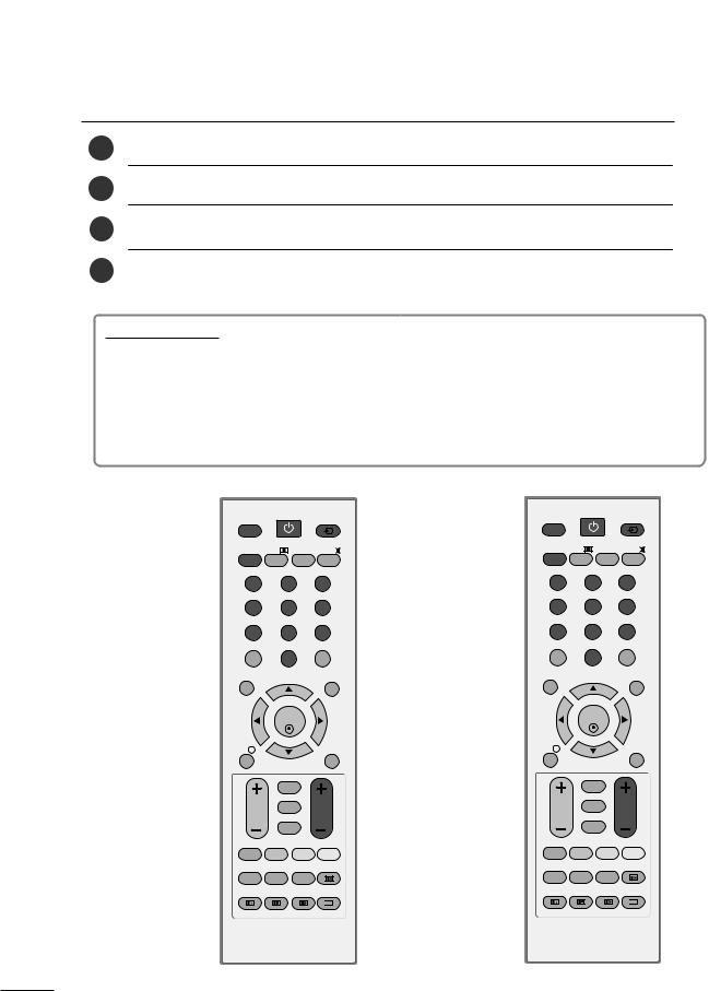
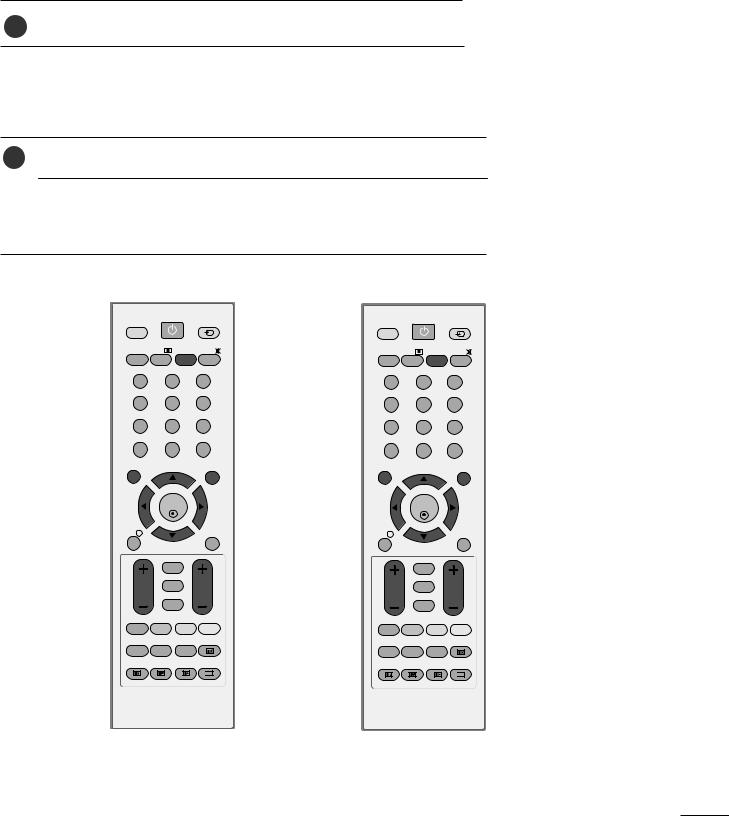
REMOTE CONTROL KEY FUNCTIONS
When using the remote control, aim it at the remote control sensor on the set.
A Type
POWER |
INPUT |
1 |
|
TV |
|
1 |
|
D/A |
|
|
|
TV/RADIO TEXT |
I/II |
MUTE |
2 |
|
|
|
|
1 |
2 |
3 |
|
4 |
5 |
6 |
3 |
|
|
|
|
7 |
8 |
9 |
2 |
|
|
|
|
LIST |
0 |
Q.VIEW |
|
POWER Switches the set on off.
TV A type : Selects digital or analogue TV mode. TV/PC B type : Selects TV or PC mode.
Switches the set on.
INPUT External input mode rotates in regular sequence. Switches the set on.
TV/RADIO Selects Radio or TV channel.
MENU EXIT
|
OK |
|
4 |
INFO i |
|
GUIDE |
|
|
BACK |
|
|
VOL |
* |
PR |
5 |
|
|||
|
FAV |
|
|
B Type
POWER |
INPUT |
|
|
TV/PC |
|
1 |
|
|
|
|
|
TV/RADIO TEXT |
I/II |
MUTE |
2 |
|
|
|
|
1 |
2 |
3 |
|
4 |
5 |
6 |
3 |
|
|
|
|
7 |
8 |
9 |
|
LIST |
0 |
Q.VIEW |
|
MENU |
|
EXIT |
|
|
OK |
|
4 |
INFO i |
|
GUIDE |
|
|
BACK |
|
|
VOL |
* |
PR |
5 |
|
|||
|
FAV |
|
|
I/II Selects the sound output.(Refer to the p.61,62)
MUTE Switches the sound on or off.
3 0~9 number Selects a programme.
button Selects numbered items in a menu.
LIST Displays the programme table.(Refer to the p.40)
Q.VIEW Returns to the previously viewed programme.
4 |
MENU Selects a menu.(Refer to the p.28) |
|
EXIT Clears all on-screen displays.
INFO i Shows the present screen information.
GUIDE Shows programme schedule.(Refer to the p.41~43)
THUMBSTICK Allows you to navigate the on-screen menus and adjust (Up/Down/Left/Right) the system settings to your preference.
OK Accepts your selection or displays the current mode.
5 VOLUME UP Adjusts the volume.
/DOWN
BACK Allows the user to move back one step in an interactive application, EPG or other user interaction function.
* No function
FAV Displays the selected favourite programme.(Refer to the p.34)
Programme Selects a programme.
UP/DOWN
24
WATCHING TV /PROGRAMME CONTROL
A Type
1
POWER |
INPUT |
|
|
TV |
|
|
|
D/A |
|
|
|
TV/RADIO TEXT |
I/II |
MUTE |
|
|
|
|
1 |
1 |
2 |
3 |
2 |
|
|
|
|
4 |
5 |
6 |
|
7 |
8 |
9 |
|
LIST |
0 |
Q.VIEW |
|
3
VOL * PR
FAV
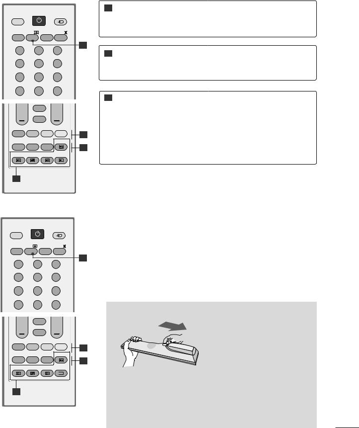
2
RATIO |
SLEEP |
SUBTITLE |
UPDATE |
3
TELETEXT These buttons are used for teletext. BUTTONS For further details, see the ‘Teletext’ section.
(Refer to the p.78~80)
Colour These buttons are used for teletext (only TELETEXT buttons models) or Programme edit.
(Refer to the p.34~35,41~43,80)
RATIO Selects your desired picture format. (Refer to the p.44,45)
SLEEP Sets the sleep timer. (Refer to the p.68)
SUBTITLE Recalls your preferred subtitle in digital mode.
BType
1
Installing Batteries
VOL * PR
FAV
2
RATIO |
SLEEP |
SUBTITLE |
UPDATE |
3
INDEX TIME HOLD REVEAL

 ?
?
1
■Open the battery compartment cover on the back and install the batteries matching correct polarity (+ with +, - with -).
■Install two 1.5V AAA batteries. Don’t mix old or used batteries with new ones.
■Close cover.
25
WATCHING TV /PROGRAMME CONTROL
TURNING ON THE TV
-TV is turned on, you will be able to use its features.
First, connect power cord correctly.
by pressing the power button on the product.
3Press the TV button on the remote control.
the remote control.
Initializing setup
If the OSD (On Screen Display) is displayed on the screen as figure after turning on the set, you can adjust the Language, Country, Time Zone, Auto programme tuning.
Note:
a.It will automatically disappear after approx. 40 seconds unless a button is pressed.
b.Press the BACK button to change current OSD into previous OSD.
A Type |
|
B Type |
POWER |
INPUT |
|
TV |
|
|
D/A |
|
|
TV/RADIO TEXT |
I/II |
MUTE |
1 |
2 |
3 |
4 |
5 |
6 |
7 |
8 |
9 |
LIST |
0 |
Q.VIEW |
MENU |
|
EXIT |
|
OK |
|
INFO i |
|
GUIDE |
|
BACK |
|
VOL |
* |
PR |
|
FAV |
|
RATIO SLEEP SUBTITLE UPDATE
INDEX TIME HOLD REVEAL

 ?
?
POWER |
INPUT |
|
TV/PC |
|
|
TV/RADIO TEXT |
I/II |
MUTE |
1 |
2 |
3 |
4 |
5 |
6 |
7 |
8 |
9 |
LIST |
0 |
Q.VIEW |
MENU |
|
EXIT |
|
OK |
|
INFO i |
|
GUIDE |
|
BACK |
|
VOL |
* |
PR |
|
FAV |
|
RATIO SLEEP SUBTITLE UPDATE
INDEX TIME HOLD REVEAL

 ?
?
26
WATCHING TV /PROGRAMME CONTROL
PROGRAMME SELECTION
1
VOLUME ADJUSTMENT
1
If you want to switch the sound off, press the MUTE button.
You can cancel this function by pressing the MUTE, VOL + or -, or I/II button.
A Type |
|
B Type |
POWER |
INPUT |
|
TV |
|
|
D/A |
|
|
TV/RADIO TEXT |
I/II |
MUTE |
1 |
2 |
3 |
4 |
5 |
6 |
7 |
8 |
9 |
LIST |
0 |
Q.VIEW |
MENU |
|
EXIT |
|
OK |
|
INFO i |
|
GUIDE |
|
BACK |
|
VOL |
* |
PR |
|
FAV |
|
RATIO SLEEP SUBTITLE UPDATE
INDEX TIME HOLD REVEAL

 ?
?
POWER |
INPUT |
|
TV/PC |
|
|
TV/RADIO TEXT |
I/II |
MUTE |
1 |
2 |
3 |
4 |
5 |
6 |
7 |
8 |
9 |
LIST |
0 |
Q.VIEW |
MENU |
|
EXIT |
|
OK |
|
INFO i |
|
GUIDE |
|
BACK |
|
VOL |
* |
PR |
|
FAV |
|
RATIO SLEEP SUBTITLE UPDATE
INDEX TIME HOLD REVEAL

 ?
?
27
WATCHING TV /PROGRAMME CONTROL
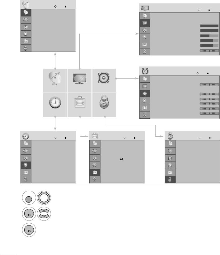
ON SCREEN MENUS SELECTION AND ADJUSTMENT
Your set's OSD (On Screen Display) may differ slightly from what is shown in this manual.
SETUP |
Move |
OK |
|
|
|
|
Auto tuning |
|
PICTURE |
|
|
Move |
OK |
|
|
|
|
|
|
|
Manual tuning |
|
Aspect Ratio |
: 16:9 |
|
|
|
|
|
|
|
|
|
|
Programme Edit |
|
Picture Mode |
: Vivid |
|
|
|
|
|
• Backlight |
100 |
|
|
|
Booster |
: On |
|
|
|
||
|
• Contrast |
100 |
|
|
||
Software Update : On |
|
|
|
|||
|
• Brightness |
50 |
|
|
||
Diagnostics |
|
|
|
|
||
|
|
• Sharpness |
70 |
|
|
|
CI Information |
|
|
|
|
||
|
|
• Colour |
70 |
|
|
|
|
|
|
|
|
||
|
|
|
• Tint |
0 |
R |
G |
|
|
|
E |
|
|
|
|
|
|
AUDIO |
|
|
Move |
OK |
|
|
|
Auto Volume |
: Off |
|
|
|
|
|
|
Balance |
|
0 |
L |
R |
SETUP |
PICTURE |
AUDIO |
Sound Mode |
: Standard |
|
|
|
|
|
|
|
• 120Hz |
0 |
- |
+ |
|
|
|
|
• 200Hz |
0 |
- |
+ |
|
|
|
|
• 500Hz |
0 |
- |
+ |
|
|
|
|
|
|
||
|
|
|
|
• 1.2KHz |
0 |
- |
+ |
TIME |
OPTION |
LOCK |
|
• 3KHz |
0 |
- |
+ |
|
|
|
|||||
|
|
|
|
|
E |
|
|
TIME |
Move |
OK |
OPTION |
Move |
OK |
LOCK |
Move |
OK |
Clock |
|
|
Menu Language |
: English |
|
Lock System |
: Off |
|
Off Time |
: Off |
|
Audio Language |
: English |
|
Set Password |
|
|
On Time |
: Off |
|
Subtitle Language : English |
|
Block Programme |
|
|
|
Sleep Timer : Off |
|
Hard of Hearing( |
) : Off |
|
Parental Guidance : Off |
|
||
Auto Sleep |
: Off |
|
Country |
: UK |
|
|
|
|
Time Zone |
: London GMT |
|
Input Label |
|
|
|
|
|
|
|
|
Key Lock |
: Off |
|
|
|
|
|
|
|
Set ID |
: 1 |
|
|
|
|
|
|
|
E |
|
|
|
|
|
MENU |
|
|
|
|
|
|
|
|
Display each menu.
OK
OK
Select a menu item.
Move to the pop up menu.
•Press the MENU or EXIT button to close the menu window.
•Press the BACK button to move to the previous menu screen.
28
WATCHING TV /PROGRAMME CONTROL
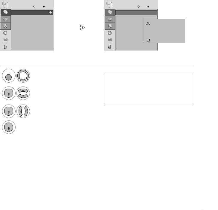
AUTO PROGRAMME TUNING
Use this to automatically find and store all available programmes.
When you start auto programming in digital mode, all previously stored service information will be deleted.
SETUP |
Move |
OK |
SETUP |
Move |
OK |
Autouto tuningtuning |
|
|
Autouto tuningtuning |
|
|
Manual tuning |
|
|
Manual tuning |
|
|
Programme Edit |
|
|
Programme Edit |
|
All service-information will be updated. |
|
|
|
|
|
|
Booster |
: On |
|
Booster |
: On |
Continue? |
|
|
Software Update : On |
|
|
Software Update : On |
|
|
|
|
|
|
|
|
|
|
|
|
|
Yes |
|
No |
|
|
||
|
|
Diagnostics |
|
|
Diagnostics |
|
|
|
|
|
||
|
|
|
|
|
|
|
|
|
|
|
||
|
|
CI Information |
|
|
CI Information |
|
|
SECAM L Search |
|
|
|
|
|
|
|
|
|
|
|
|
|
||||
|
|
|
|
|
|
|
|
|
|
|
|
|
|
|
|
|
|
|
|
|
|
|
|
|
|
|
|
|
|
|
|
|
|
|
|
|
|
|
|
|
|
|
|
|
|
|
|
|
|
|
|
1MENU
Select SETUP.
OK |
Select Auto Tuning. |
|
•Use NUMBER buttons to input a 4-digit password in Lock System ‘On’.
•If you wish to keep on auto tuning, select YES using the F G button. Then, press the OK button. Otherwise, select NO.
OK |
Select Yes. |
|
|
OK |
Run Auto tuning. |
|
•Press the MENU or EXIT button to close the menu window.
•Press the BACK button to move to the previous menu screen.
29
Loading...