


 Loading...
LG M2762D, M2362DP, M2362D, M2762DP, M2262DP User Manual
...ENGLISH
OWNER’S MANUAL
MONITOR TV
Please read this manual carefully before operating your set and retain it for future reference.
MONITOR TV MODELS
M2262D M2262DP
M2362D M2362DP
M2762D M2762DP
www.lg.com
PREPARATION
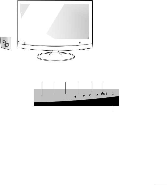
FRONT PANEL CONTROLS
■This is a simplified representation of the front panel. The image shown may be somewhat different from your set.
|
|
|
|
|
|
|
|
|
|
|
|
|
|
|
|
|
|
|
|
|
|
|
|
|
|
|
|
|
|
|
|
|
|
|
|
|
|
|
|
|
|
|
|
|
|
|
|
|
|
|
|
|
|
|
|
|
|
|
|
|
|
|
|
|
|
|
|
|
|
|
|
|
|
|
|
|
|
|
|
|
|
|
|
|
|
|
|
|
|
|
|
|
|
|
|
|
|
|
|
|
|
|
|
|
|
|
|
|
|
|
|
|
|
|
|
|
|
|
|
|
|
|
|
|
|
|
|
|
|
|
|
|
|
|
|
|
|
|
|
|
|
|
|
|
|
|
|
|
|
|
|
|
|
|
|
|
|
|
|
|
|
|
|
|
|
|
|
|
|
|
|
|
|
|
|
|
|
|
|
|
|
|
|
|
|
|
|
|
|
|
|
|
|
|
|
|
|
|
|
|
|
|
|
|
|
|
|
|
|
|
|
|
|
|
|
|
|
|
|
|
|
|
|
|
|
|
|
|
|
|
|
|
|
|
|
|
|
|
|
|
|
|
|
|
|
|
|
|
|
|
|
|
|
|
|
|
|
|
|
|
|
|
|
|
|
|
|
|
|
|
|
|
|
|
|
|
|
|
|
|
|
|
|
|
|
|
|
|
|
|
|
|
|
|
|
|
|
|
|
|
|
|
|
|
|
|
|
|
|
|
|
|
|
|
|
|
|
|
|
|
|
|
|
|
|
|
|
|
|
|
|
|
|
|
|
|
|
|
|
|
|
|
|
|
|
|
|
|
|
|
|
|
|
|
|
|
|
|
|
|
|
|
|
|
|
|
|
|
|
|
|
|
|
|
|
|
|
|
|
|
|
|
|
|
|
|
|
|
|
|
|
|
|
|
|
|
|
|
|
|
|
|
|
|
|
|
|
|
|
|
|
|
|
|
|
|
|
|
|
|
|
|
|
|
|
|
|
|
|
|
|
|
|
|
|
|
|
|
|
|
|
|
|
|
|
|
|
|
|
|
|
|
|
|
|
|
|
|
|
|
|
|
|
|
|
|
|
|
|
|
|
|
|
|
|
|
|
|
|
|
|
|
|
|
|
|
|
|
|
|
|
|
|
|
|
|
|
|
|
|
|
|
|
|
|
|
|
|
|
|
|
|
|
|
|
|
|
|
|
|
|
|
|
|
|
|
|
|
|
|
|
|
|
|
|
|
|
|
|
|
|
|
|
|
|
|
|
|
|
|
|
|
|
|
|
|
|
|
|
|
|
|
|
|
|
|
|
|
|
|
|
|
|
|
|
|
|
|
|
|
|
|
|
|
|
|
|
|
|
|
|
|
|
|
|
|
|
|
|
|
|
|
|
|
|
|
|
|
|
|
|
|
|
|
|
|
|
|
|
|
|
|
|
|
|
|
|
|
|
|
|
|
|
|
|
|
|
|
|
|
|
|
|
|
|
|
|
|
|
|
|
|
|
|
|
|
|
|
|
|
|
|
|
|
|
|
|
|
|
|
|
|
|
|
|
|
|
|
|
|
|
|
|
|
|
|
|
|
|
|
|
|
|
|
|
|
|
|
|
|
|
|
|
|
|
|
|
|
|
|
|
|
|
|
|
|
|
|
|
|
|
|
|
|
|
|
|
|
|
|
|
|
|
|
|
|
|
|
|
|
|
|
|
|
|
|
|
|
|
|
|
|
|
|
|
|
|
|
|
|
|
|
|
|
|
|
|
|
|
|
|
|
|
|
|
|
|
|
|
|
|
|
|
|
|
|
|
|
|
|
|
|
|
|
|
|
|
|
|
|
|
|
|
|
|
|
|
|
|
Headphone |
|
|
IR receiver |
|
|
|
|
|
|
|
|
|
|
|
|
|
|
|
|
|
|||||||||
|
Jack |
(Remote controller |
|
|
|
|
|
|
|
|
|
|
|
|
|
|
|
|
|||||||||||
|
|
|
|
|
|
receiver) |
|
|
|
|
|
|
|
|
|
|
|
|
|
|
|
|
|||||||
|
|
|
|
|
|
|
|
|
|
|
|
|
|
|
|
CHANNEL |
|||||||||||||
|
|
|
|
|
|
|
|
|
|
INPUT |
|
MENU |
ENTER |
VOLUME |
|||||||||||||||
|
|
|
|
|
|
|
|
|
|
Button |
|
Button |
Button |
Buttons |
|
Buttons |
|||||||||||||
Power Indicator illuminates blue when the set is switched on. Note:You can adjust Power indicator in the OPTION menu.
Power
Button
INPUT
MENU
ENTER |
VOL |
CH |
|
||
|
|
Light Sensor
This is lens for light sensor select outside luminance, when setting AUTO BRIGHT ON.
1
PREPARATION
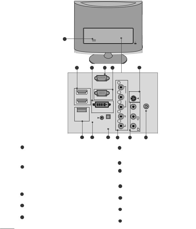
BACK PANEL INFORMATION
■This is a simplified representation of the back panel. The image shown may be somewhat different from your set.
1 |
|
|
|
|
|
2 |
3 |
4 |
5 |
|
6 |
|
|
|
|
COMPONENT |
AV-IN |
|
|
|
|
IN |
|
|
|
RS-232C |
|
Y |
|
|
(CONTROL & SERVICE) |
|
|
||
|
1 |
PB |
VIDEO |
S-VIDEO |
HDMI IN |
RGB IN |
|
||
|
ANTENNA/ |
|||
|
|
|
|
|
|
2 |
PR |
|
CABLE IN |
|
DVI-D IN |
L |
|
VIDEO |
|
|
(MONO) |
||
|
|
|
||
SERVICE |
AUDIO IN |
|
AUDIO |
|
ONLY |
OUT |
|
AUDIOL |
|
(RGB/DVI) |
R |
|
|
|
|
OPTICAL |
|
|
|
|
DIGITAL |
|
|
|
|
|
|
|
R |
|
9 |
10 |
11 |
1 |
|
6 |
|
|
This set operates on AC power. The voltage is indicated |
|
Standard definition (480i), but better quality than |
|
on the Specifications page. Never attempt to operate |
|
standard A/V input. |
|
the set on DC power. |
|
SERVICE ONLY PORT |
|
HDMI Input |
|
|
2 |
|
|
|
|
High definition inputs. These two inputs accept TV |
8 |
RGB/DVI Audio Input |
|
Video, not PC Video. They also accept TV Video from a |
|
This is the audio input for the RGB and DVI-D video |
|
DVI connection when using an adapter. The HDMI |
|
inputs. |
|
inputs support video and audio. When using an adapter |
|
|
|
for DVI, they only accept video. |
9 |
Optical Digital Audio Out |
|
DVI-D Input |
|
Use this to export audio to an external amplifer. |
3 |
|
|
|
|
Digital PC input. |
10 |
Component Input |
|
RS-232C IN (CONTROL & SERVICE) PORT |
|
High definition analog input. |
4 |
|
|
|
|
Serial port used for external control or service. |
11 |
Audio/Video Input |
|
RGB INPUT (PC) |
|
Standard definition input. |
5 |
|
|
|
|
Analog PC input. Also known as VGA. |
12 |
Antenna Input |
|
|
|
Connect over-the-air or cable signals to this jack. |
2
PREPARATION |
<M2262D/M2362D/M2262DP/M2362DP> |
|
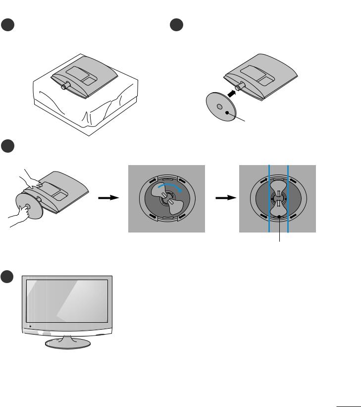
STAND INSTALLATION
■ The image shown may be somewhat different from your set.
1 Carefully place the product screen side down on a |
2 Insert the Stand Base into the product. |
cushioned surface that will protect product and |
|
screen from damage. |
|
Stand Base
3 Turn the Stand Base Lock through 90° to fix the stand base to the stand body.
N
E
P O
O
P
E
N
N
E
P O
O
P E N
Stand Base Lock
4 |
3
PREPARATION |
<M2762D/M2762DP> |
|
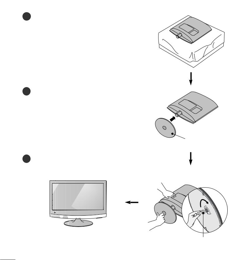
STAND INSTALLATION
■The image shown may be somewhat different from your set.
1 Carefully place the product screen side down on a cushioned surface that will protect product and screen from damage.
2 Insert the Stand Base into the product.
Stand Base
3Use a Coin on the bottom of the stand base and turn the screw clockwise to tighten.
C n
4

PREPARATION |
<M2262D/M2362D/M2262DP/M2362DP> |
|
DETACHING STAND
■ The image shown may be somewhat different from your set.
1Place the set screen side down on a cushion or soft cloth.
2Detach the monitor to the Stand Base by turning the screw to the left.
 Stand Base
3Turn the Stand Base Lock through 90° to separate the stand base from the stand body.
N
E
P O
O
P
E
N
N
E
P O
O
P
E
N
4Pushing Latch inside, Take the stand base from stand body.
N
E
P
O
O
P
E
N
Latch
5
PREPARATION |
<M2762D/M2762DP> |
|
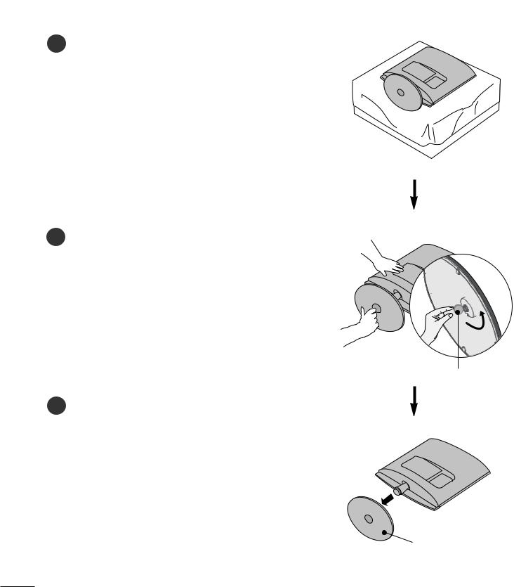
DETACHING STAND
■ The image shown may be somewhat different from your set.
1Place the set screen side down on a cushion or soft cloth.
2Detach the stand base from the set by turning the screw to the left with a coin.
C n
3Pull the stand base.
Stand Base
6
PREPARATION
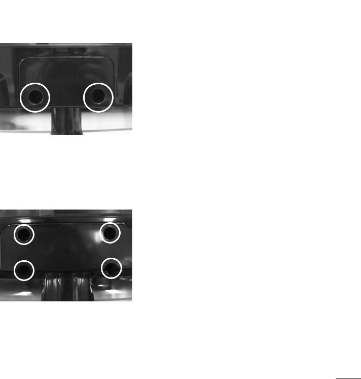
DETACHING STAND BODY
■The image shown may be somewhat different from your set.
■Remove the Stand Body in the same way as the following when using it as a Wall Hook.
<M2262D/M2362D/M2262DP/M2362DP>
1.Remove the screw 2 point.
2.Pull the stand body.
<M2762D/M2762DP>
1.Remove the screw 4 point.
2.Pull the stand body.
7
PREPARATION
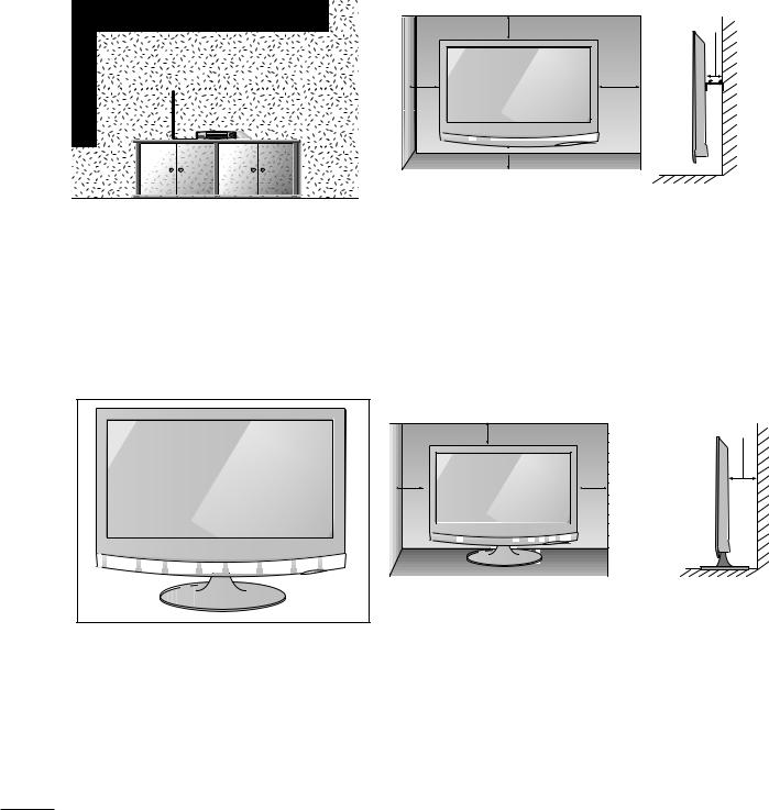
WALL MOUNT: HORIZONTAL INSTALLATION
For proper ventilation, allow a clearance of 10 cm on each side and from the wall. Follow the instructions included with the wall mount.
10 cm
10 cm
10 cm |
10 cm |
10 cm
DESKTOP PEDESTAL INSTALLATION
For proper ventilation, allow a clearance of 10 cm on each side and from the wall.
10 cm
10 cm |
10 cm |
|
10 cm
8
PREPARATION
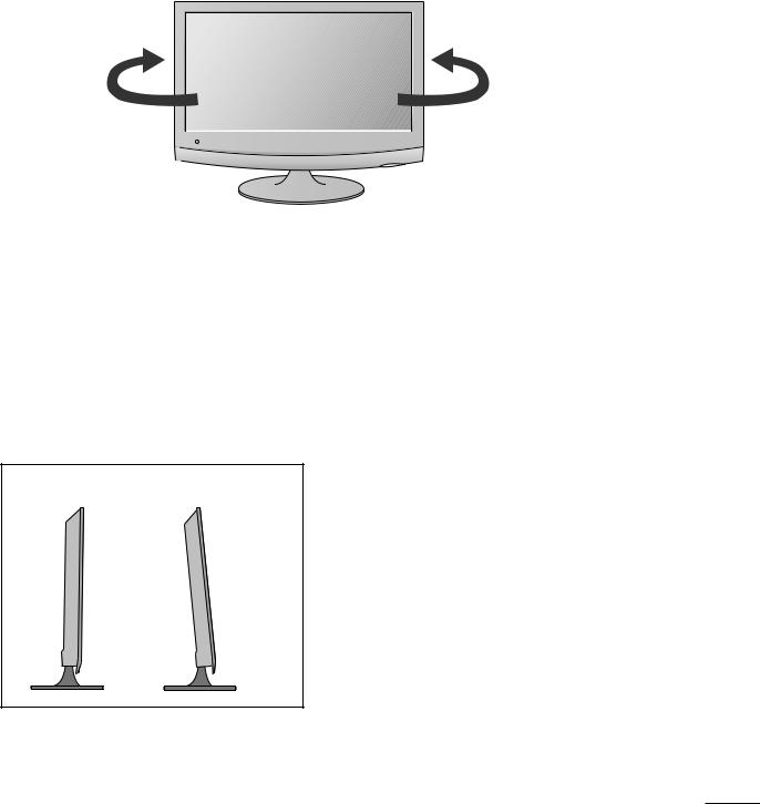
SWIVEL STAND(Only M2762D/M2762DP)
■ The image shown may be somewhat different from your set.
After installing the set, you can adjust the set manually to the left or right direction by 179 degrees to suit your viewing position.
179° |
179° |
POSITIONING YOUR DISPLAY
■ The image shown may be somewhat different from your set.
Adjust the position of the panel in various ways for maximum comfort.
• Tilt range
-5° |
15° |
9
PREPARATION
LOCATION
Position your set so that no bright light or sunlight falls directly onto the screen. Care should be taken not to expose the set to any unnecessary vibration, moisture, dust or heat. Also, ensure that the set is placed in a position to allow a free flow of air. Do not cover the ventilation openings on the back cover.
If you intend to mount the set to a wall, attach the wall mounting interface (optional parts) to the back of the set. When you install the set using the wall mounting interface (optional parts), attach it carefully so it will not drop.
-Be sure to use screws and a wall mount that meet VESA standards.
-Using screws longer than those recommended might damage the product.
-Using screws that do not meet VESA standards might either damage the product or result in it coming away from the wall. We will not be held responsible for any damage resulting from failure to follow these instructions.
<Screw Mounting Interface Dimension > M2262D/M2362D/M2262DP/M2362DP : 100 mm x 100 mm hole spacing M2762D/M2762DP : 200 mm x 100 mm hole spacing
* Wall mount interface(LG) : RW120 <M2262D/M2362D/M2262DP/M2362DP>
RW240 <M2762D/M2762DP>
Warning:
When adjusting the angle of the screen, do not put your finger(s)in between the head of the monitor and the stand body. You can hurt your finger(s).
RW120 |
RW240 |
10
PREPARATION
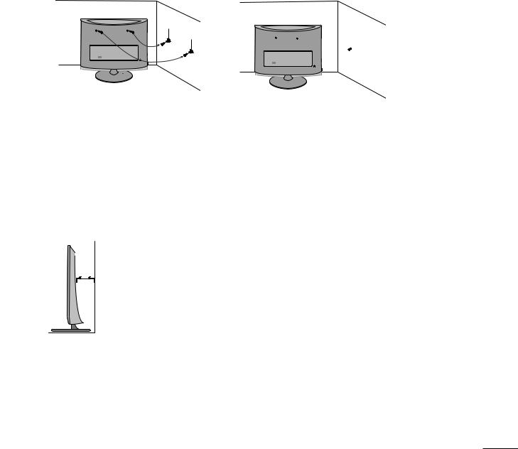
SECURING THE SET TO THE WALL TO PREVENT FALLING WHEN THE SET IS USED ON A STAND(Only M2762D/M2762DP)
■ Image shown may differ from your set.
We recommend that you set up the set close to a wall so it cannot fall over if pushed backwards. Additionally, we recommend that the set be attached to a wall so it cannot be pulled in a forward direction, potentially causing injury or damaging the product.
Caution: Please make sure that children don’t climb on or hang from the set.
■Insert the eye-bolts (or set brackets and bolts) to tighten the product to the wall as shown in the picture. *If your product has the bolts in the eye-bolts position before inserting the eye-bolts, loosen the bolts. * Insert the eye-bolts or set brackets/bolts and tighten them securely in the upper holes.
Secure the wall brackets with the bolts (sold separately) to the wall. Match the height of the bracket that is mounted on the wall to the holes in the product.
Ensure the eye-bolts or brackets are tightened securely.
■ Use a sturdy rope or cord (sold separately) to tie the product. It is safer to tie the rope so it becomes horizontal between the wall and the product.
! NOTE
G When moving the set, undo the cords first.
G Use a platform or cabinet strong enough and large enough to support the size and weight of the set.
G To use the set safely make sure that the height of the bracket on the wall and the one on the set are the same.
11
PREPARATION
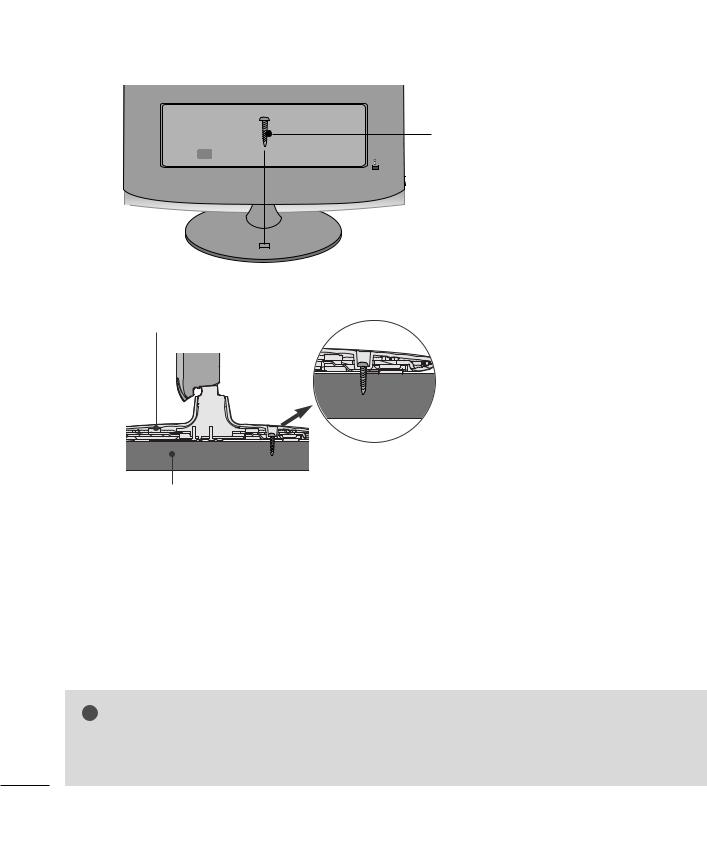
ATTACHING THE TV TO A DESK (Only M2762D/M2762DP)
■ The image shown may be somewhat different from your set.
The TV |
forward/backward direction,potentially causing |
injury or |
|
1-Screw
(provided as parts of the product)
Stand |
Desk
! WARNING
G To prevent TV from falling over,the TV should be securely attached to the floor/wall per installation instructions. Tipping,shaking, or rocking the machine may cause injury.
12
PREPARATION
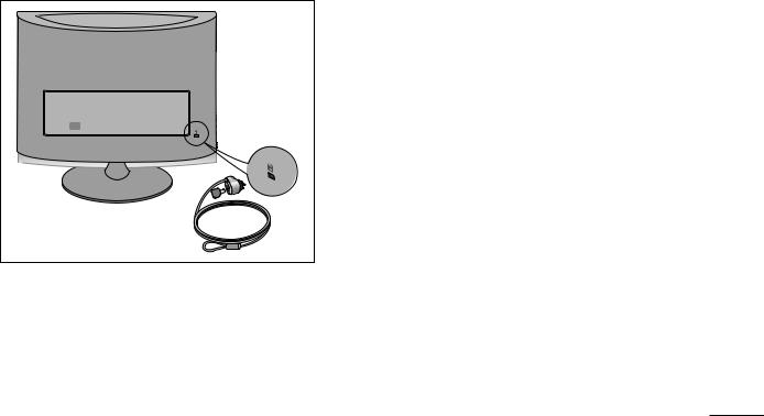
KENSINGTON SECURITY SYSTEM
-The product is equipped with a Kensington Security System connector on the back panel. Connect the Kensington Security System cable as shown below.
-For detailed installation and use of the Kensington Security System, refer to the user’s guide provided with the Kensington Security System.
For further information, contact http://www.kensington.com, the internet homepage of the Kensington company. Kensington sells security systems for expensive electronic equipment such as notebook PCs and LCD projectors.
NOTE
- The Kensington Security System is an optional accessory available at most electronics stores.
NOTES
a.If the product feels cold to the touch, there may be a small “flicker” when it is turned on. This is normal, there is nothing wrong with product.
b.Some minute dot defects may be visible on the screen, appearing as tiny red, green, or blue spots. However, they have no adverse effect on the monitor's performance.
c.Avoid touching the LCD screen or holding your finger(s) against it for long periods of time.
13
EXTERNAL EQUIPMENT SETUP
■ To prevent equipment damage, never plug in any power cords until you have finished connecting all equipment.
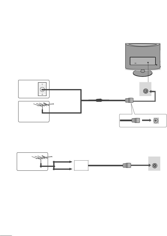
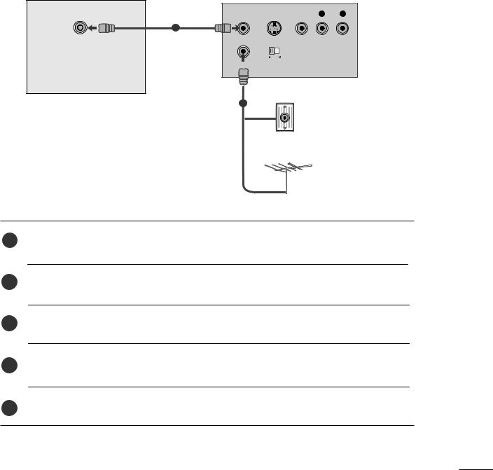
ANTENNA CONNECTION
■For optimum picture quality, adjust antenna direction.
■An antenna cable and converter are not supplied.
Wall |
Multi-family Dwellings/Apartments |
|
(Connect to wall antenna socket) |
||
Antenna AC |
||
|
||
Socket |
|
RF Coaxial Wire (75  )
)
Outdoor
Antenna
(VHF, UHF) Single-family Dwellings /Houses
(Connect to wall jack for outdoor antenna)
UHF
Antenna |
Signal |
|
|
|
Amplifier |
|
VHF |
ANTENNA/
CABLE IN
ANTENNA/
CABLE IN
■In poor signal areas, to get better picture quality, install a signal amplifier to the antenna as shown above.
■If signal needs to be split for two TVs, use an antenna signal splitter for connection.
14
EXTERNAL EQUIPMENT SETUP
■To prevent the equipment damage, never plug in any power cords until you have finished connecting all equipment.
■The image shown may be somewhat different from your set.
HD RECEIVER SETUP
When connecting with a component cable
1Connect the SET-TOP outputs to the COMPONENT IN VIDEO sockets (Y PB PR) on the set.
COMPONENT IN AUDIO sockets of the set.
Press the INPUT button to select Component.
Signal
480i
480p
576p
720p/1080i
1080p
COMPONENT
IN
Y
PB
PR |
VIDEO |
|
|
L |
|
R |
AUDIO |
|
Component |
HDMI |
Yes |
No |
Yes |
Yes |
No |
Yes |
Yes |
Yes |
Yes |
Yes |
1
2
15
EXTERNAL EQUIPMENT SETUP
When connecting with a HDMI
1
1 |
of the digital set-top box to the |
|
HDMI IN |
||
|
2
1
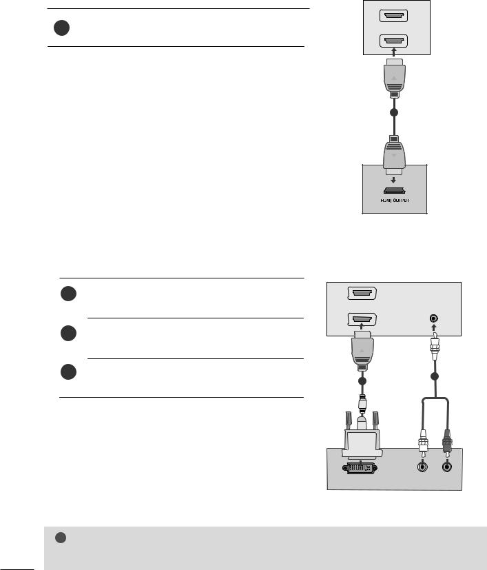
When connecting with a HDMI to DVI cable
1Connect the digital set-top box to HDMI IN jack on the set.
digital set-top box to on the set.
Turn on the digital set-top box. (Refer to the owner’s manual for the digital set-top box.)
1
AUDIO IN (RGB/DVI)
2
2
1
L |
AUDIO |
R |
DVI OUTPUT
! NOTE
G HDMI Input does not support PC mode. If it is connected PC, the screen may not display properly.
16
EXTERNAL EQUIPMENT SETUP
DVD SETUP
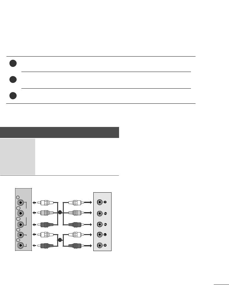
When connecting with a component cable
1Connect the video output sockets (Y PB PR) of the DVD to the COMPONENT IN VIDEO sockets (Y PB PR) of the set.
ONENT IN AUDIO sockets of the set.
Press the INPUT button to select Component.
Press the PLAY button on the DVD.
The DVD playback picture appears on the screen.
Component Input ports
To get better picture quality, connect a DVD player to the component input ports as shown below.
Component ports on the set |
Y |
PB |
PR |
|
|
|
Y |
PB |
PR |
Video output ports |
Y |
B-Y |
R-Y |
|
on DVD player |
Y |
Cb |
Cr |
|
|
|
Y |
Pb |
Pr |
COMPONENT |
|
|
|
|
|
IN |
|
|
|
Y |
|
|
|
|
PB |
VIDEO |
|
|
|
PR |
|
|
|
|
|
|
|
|
|
L |
|
|
|
|
R |
AUDIO |
2 |
|
|
|
|
|
||
17
EXTERNAL EQUIPMENT SETUP
When connecting S-Video
1 |
set. |
2Connect the audio output of the DVD to the AUDIO in put on the set.
AV-IN
S-VIDEO |
|
-S |
|
1 |
VIDEO |
|
|
VIDEO |
VIDEO |
(MONO) |
L |
L |
2 |
|
|
AUDIO |
R |
R |
|
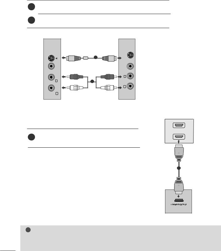
When connecting HDMI cable
1
HDMI IN
1 |
HDMI output of the DVD to the HDMI IN |
|
2 |
||
|
1
! NOTE
G HDMI supports video and audio. You do not need to connect a sperate audio cable.
G If the DVD player does not support Auto HDMI, you need to set the DVD output resolution appropriately.
18
EXTERNAL EQUIPMENT SETUP
VCR SETUP
■To avoid picture noise (interference), leave an adequate distance between the VCR and the set.
■If a user uses 4:3 picture format for a long time, an afterimage may remain on the sides of the screen for a short time.
When connecting with an antenna
ANTENNA/ |
ANT OUT S-VIDEO VIDEO |
|
|
CABLE IN |
L |
R |
1
OUTPUT
IN SWITCH
2 |
Wall Jack |
Antenna
1 |
to the antenna socket of the set. |
2Connect the antenna cable to the RF aerial in socket of the VCR.
3Store the VCR channel on a desired channel number using the ‘Manual channel tuning’ section.
4Select the Channel number where the VCR channel is stored.
5 Press the PLAY button on the VCR.
19
EXTERNAL EQUIPMENT SETUP
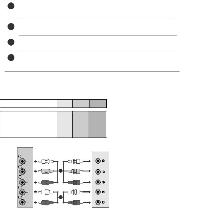
When connecting with a RCA cable
1Connect the audio/video out sockets of the VCR to AUDIO/VIDEO in sockets of the set.
Press the PLAY button on the VCR.
The VCR playback picture appears on the screen.
AV-IN
S-VIDEO
R AUDIO L (MONO) VIDEO
1
R L VIDEO VIDEO-S
! NOTE
G If you have a mono VCR, connect the audio cable from the VCR to the AUDIO L/MONO jack of the set.
When connecting with an S-Video cable
1Connect the S-Video socket of the VCR to the S- VIDEO socket of the set.
VCR
Press the INPUT button to select AV.
Press the PLAY button on the VCR.
The VCR playback picture appears on the screen.
AV-IN
S-VIDEO |
|
-S |
|
1 |
VIDEO |
|
|
VIDEO |
VIDEO |
(MONO) |
L |
L |
|
AUDIO |
R |
R |
|
20
EXTERNAL EQUIPMENT SETUP
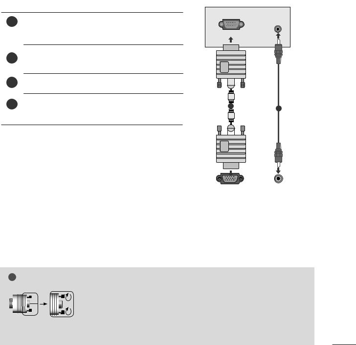
PC SETUP
This product provides Plug and Play capability, meaning that the PC adjusts automatically to the set's settings.
When connecting with a D-sub 15 pin cable
1Connect the signal cable from the monitor output socket of the PERSONAL COMPUTER to the PC input socket of the set.
the AUDIO IN
Press the INPUT button to select RGB.
The set can be operated as a PC monitor.
AUDIO IN
(RGB/DVI)
(PC)
1 |
2 |
|
|
|
|
|
|
|
|
|
|
|
|
|
|
|
|
|
|
|
|
|
|
|
|
|
|
|
|
|
|
|
|
|
|
|
|
|
|
|
|
|
|
|
|
|
|
RGB OUTPUT |
AUDIO |
|||||||
|
|
|
|
|
|
|
|
|
! NOTE
G Connect the signal input cabel and tighten the screws by turning them clockwise.
G User must use shielded signal interface cables (D sub 15 pin cable, DVI cable) with ferrite cores to maintain standard compliance for the product.
21
EXTERNAL EQUIPMENT SETUP
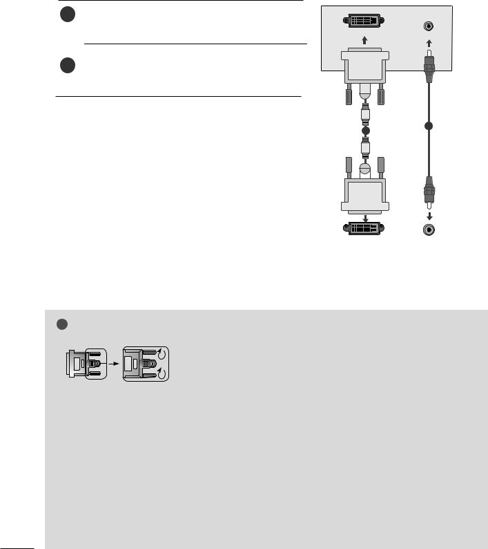
When connecting with a DVI cable
1Connect the DVI output of the PC to the DVI-D IN jack on the set.
DVI-D IN (PC)
AUDIO IN (RGB/DVI)
PC to the AUDIO
2
1
|
|
|
|
|
|
|
|
|
|
|
|
|
|
|
|
|
|
|
|
|
|
|
|
|
|
|
|
|
|
|
|
|
|
|
|
|
|
|
|
|
|
|
|
AUDIO |
|
DVI OUTPUT |
|
||||||
|
|
|
|
|
|
|
|
|
! NOTE
G Connect the signal input cabel and tighten the screws by turning them clockwise.
G If the set is cold, there may be a small “flicker” when the set is switched on. This is normal, there is nothing wrong with the set.
G If possible, use the 1920 x 1080 @ 60 Hz video mode to obtain the best image quality for your LCD monitor. If used with other resolutions, some scaled or processed pictures may appear on the screen. The set has been preadjusted to the mode 1920 x 1080 @ 60 Hz.
G Some dot defects may appear on the screen, like Red, Green or Blue spots. However, this will have no impact or effect on the monitor performance.
G Do not press the LCD screen with your finger for a long time as this may some temporary distortion effects on the screen.
G Avoid keeping a fixed image on the set’s screen for pro-
longed periods of |
The fixed image may become |
permanently imprinted |
the screen; use a screen |
saver when possible. |
|
22
EXTERNAL EQUIPMENT SETUP
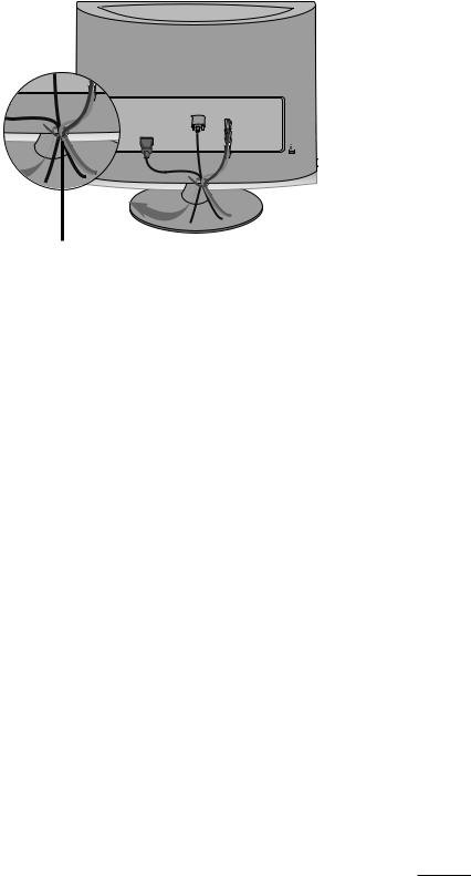
BACK COVER FOR WIRE ARRANGEMENT
Tie cables together with a cable tie as shown in the illustration.
R
R
23
EXTERNAL EQUIPMENT SETUP
SUPPORTED DISPLAY RESOLUTION
RGB/DVI[PC]
Resolution |
Horizontal |
Vertical |
|
Frequency(kHz) |
Frequency(Hz) |
||
|
|||
|
|
|
|
720x400 |
31.468 |
70 |
|
640x480 |
31.469 |
60 |
|
37.500 |
75 |
||
|
|||
800x600 |
37.879 |
60 |
|
46.875 |
75 |
||
|
|||
1024x768 |
48.363 |
60 |
|
60.123 |
75 |
||
|
|||
1152x864 |
67.500 |
75 |
|
1280x1024 |
63.981 |
60 |
|
79.976 |
75 |
||
|
|||
1680x1050 |
64.674 |
60 |
|
65.290 |
60 |
||
|
|||
1600x1200 |
75.000 |
60 |
|
1920x1080 |
66.587 |
60 |
HDMI[DTV] supported mode
Resolution |
Horizontal |
Vertical |
|
Frequency(kHz) |
Frequency(Hz) |
||
|
|||
|
31.469 |
60 |
|
720x480/60p |
|||
31.5 |
60 |
||
|
|||
720x576/50p |
31.25 |
50 |
|
1280x720/50p |
37.5 |
50 |
|
1280x720/60p |
44.96 |
60 |
|
45 |
60 |
||
|
|||
1920x1080/60i |
33.72 |
60 |
|
33.75 |
60 |
||
|
|||
1920x1080/50i |
28.125 |
50 |
|
1920x1080/24p |
27 |
24 |
|
1920x1080/30p |
33.75 |
30 |
|
1920x1080/50p |
56.25 |
50 |
|
1920x1080/60p |
67.43 |
60 |
|
67.5 |
60 |
||
|
|||
|
|
|
24
EXTERNAL EQUIPMENT SETUP
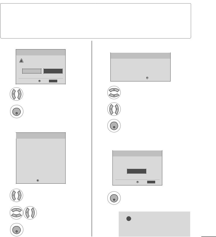
INITIAL SETTING
This Function guides the user to easily set the essential items for viewing the TV for the first time when purchasing the TV. If will be displayed on the screen when turning the TV on for the first time. It can also be activated from the user menus.
■Default selection is “Home”. We recommend setting the TV to “Home” mode for the best picture in your home environment.
■“In-store” Mode is only intended for use in retail environments. Customers can adjust the “Picture menu - Picture mode” manually while inspecting the TV, but the TV will automatically return to preset in-store mode after 5 minutes.
Step1. Mode setting |
Step3. Option setting |
Step1. Mode Setting |
|
|
! |
. |
|
you want. |
|
|
|
|
|
In Store |
Home |
|
Enter |
RETURN |
Exit |
Option Setting
Language Setting |
F |
English |
G |
|
|
|
|
||||||
|
|
|
|
|
|
|
Language Setting |
|
English |
|
|
|
|
|
|
|
|
|
|
|
|
Enter |
|
|
Exit |
||
|
|
RETURN |
||||
1 |
anguage Setting or |
Select Home Mode. |
age Setting. |
2
ENTER
Step2. Time setting
. Time Setting
Time Setting |
F |
Auto |
G |
||
Year |
|
|
|
|
|
|
---- |
|
|||
|
|
|
|
|
|
Month |
|
-- |
|
||
|
|
|
|
|
|
Date |
|
-- |
|
||
|
|
|
|
|
|
Hour |
|
-- |
|
||
|
|
|
|
|
|
Minute |
|
-- |
|
||
|
|
|
|
|
|
Time Zone |
|
Eastern |
|
||
|
|
|
|
|
|
Daylight Saving |
|
Auto |
|
||
|
|
|
|
|
|
Enter |
|
|
|
||
|
RETURN |
Exit |
|
||
2
Select your desired language.
3
ENTER
Step4. Auto Tuning
Step4. Auto Tuning
Auto Tuning can change channel map.
Do you want to start Auto Tuning?
Enter
Enter |
RETURN Exit |
3
Select Auto or Manual. |
ENTER |
Start Auto |
Tuning. |
|
|||
|
|
|
lect desired time option.
! NOTE
G You can also adjust Initial Setting
ENTER
in the OPTION menu.
25
WATCHING TV / CHANNEL CONTROL
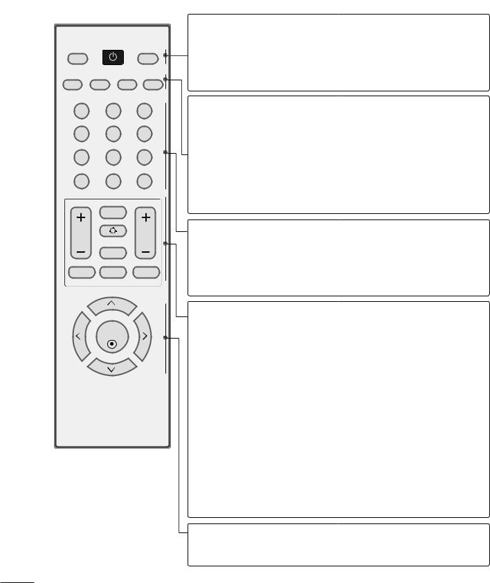
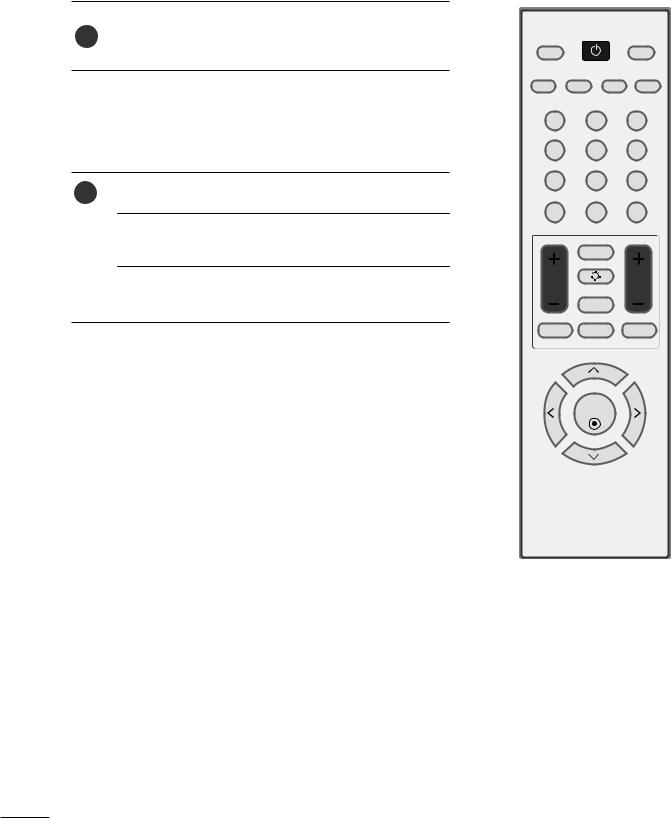
REMOTE CONTROL KEY FUNCTIONS
When using the remote control, aim it at the remote control sensor on the set.
POWER
TV/PC |
INPUT |
PICTURE SOUND SAP RATIO
1 |
2 |
3 |
4 |
5 |
6 |
7 |
8 |
9 |
- |
0 |
FLASHBK |
|
FAV |
|
|
LIGHTING |
|
VOL |
|
CH |
|
MUTE |
|
Q.MENU |
MENU |
RETURN |
ENTER
POWER Turns your set on or off.
TV/PC Selects TV or PC mode.
Switches the set on.
INPUT External input modes rotate in regular sequence
PICTURE Toggles through the factory preset picture settings depending on the viewing environment.
SOUND Toggles through preset sound settings.
*Toggles through Mono, Stereo, or SAP when using analog audio.
*DTV mode: Changes the audio language.
RATIO Change the spect ratio.
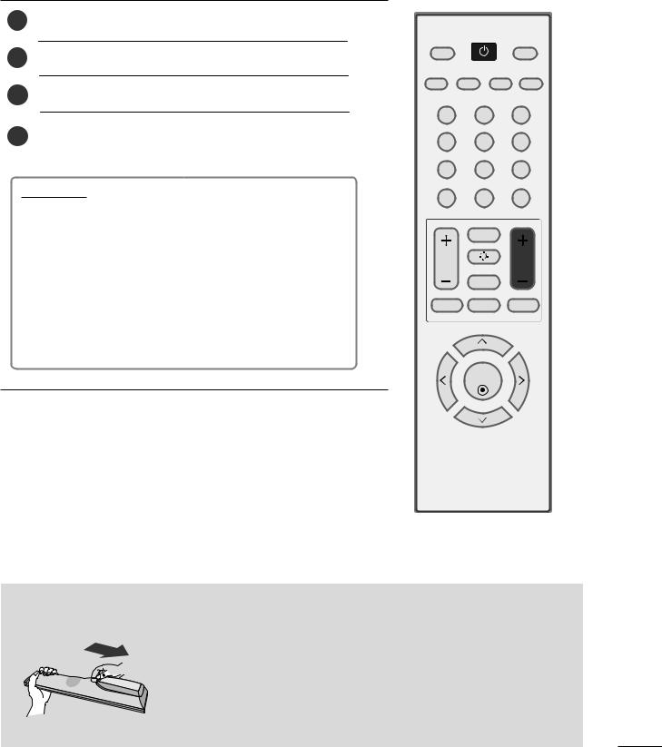
NUMBER button
_(DASH) Used to enter a program number for multiple program channels such s 2-1,2-2,etc.
FLASHBK Tunes to the last channel viewed.
VOLUME UP Increase/decrease the sound level. /DOWN
FAV Scroll through the programmed Favorite channels.
LIGHTING Press the Lighting button to turn the decoration lighting on/off.
MUTE Switch the sound on or off.
CHANNEL Select available channels.
UP/DOWN
Q.MENU Select the desired quick menu source.
MENU Displays the main menu.
RETURN Allows the user to move return one step in an interactive application or other user interaction function.
THUMBSTICK Navigate the on-screen menus and adjust the system set-
(Up/Down/LeftRight/ENTER) tings to your preference.
26
WATCHING TV / CHANNEL CONTROL
TURNING ON THE TV
1First, connect the power cord correctly.
the power button on the product.
3Press the TV/PC button on the remote control.
number but-
tup Menu
If the OSD (On Screen Display) is displayed on the screen as figure after turning on the set, you can adjust the Language, Country, Time Zone, Auto channel tuning.
Note:
a.It will automatically disappear after approx. 40 seconds unless a button is pressed.
b.Press the RETURN button to change current OSD into regular OSD.
POWER
TV/PC |
INPUT |
PICTURE SOUND SAP RATIO
1 |
2 |
3 |
4 |
5 |
6 |
7 |
8 |
9 |
- |
0 |
FLASHBK |
|
FAV |
|
|
LIGHTING |
|
VOL |
|
CH |
|
MUTE |
|
Q.MENU |
MENU |
RETURN |
ENTER
Installing Batteries
■ Open the battery compartment cover on the back and install the batteries matching correct polarity (+ with +, - with -).
■ Install two 1.5 V AAA batteries. Don’t mix old or used batteries with new ones.
■ Close cover.
■ To remove the batteries, perform the installation actions in reverse.
27
WATCHING TV / CHANNEL CONTROL
CHANNEL SELECTION
or - or NUMBER buttons to select a
1
VOLUME ADJUSTMENT
1 |
+ or - button to adjust the volume. |
If you want to switch the sound off, press the MUTE button.
You can cancel this function by pressing the MUTE,
VOL + or -.
POWER
TV/PC |
INPUT |
PICTURE SOUND SAP RATIO
1 |
2 |
3 |
4 |
5 |
6 |
7 |
8 |
9 |
- |
0 |
FLASHBK |
|
FAV |
|
|
LIGHTING |
|
VOL |
|
CH |
|
MUTE |
|
Q.MENU |
MENU |
RETURN |
ENTER
28
Loading...