


LDG3015ST
LG Electronics LDG3015ST, LDG3036ST, LDG3035ST, LDG3031ST, LDG3037ST User Manual
...
INSTALLATION MANUAL
GAS DOUBLE OVEN
RANGE
LDG3017ST
LDG3016ST
LDG3015ST/SB/SW
LDG3011ST
LDG3037ST
LDG3036ST
LDG3035ST/SB/SW
LDG3031ST
Please read this guide thoroughly before installation.
www.lge.com
ENGLISH
ESPAÑOL
MFL62177703
2
INSTA L L ATION INSTRU C T I O N S
INSTALLATION SAFETY INSTRUCTIONS
READ ALL INSTRUCTIONS BEFORE INSTALLATION
BEFORE YOU BEGIN
Read these instructions completely
and carefully.
Installation of this range must conform with local
codes, or in the absence of local codes, with the
National Fuel Gas Code, ANSI Z223.1/NFPA.54,
latest edition. In Canada, installation must
conform with the current Natural Gas Installation
Code, CAN/CGAB149.1 or the current Propane
Installation Code, CAN/CGA-B149.2, and with
local codes where applicable. This range has been
design-certified by CSA International according
to ANSI Z21.1, latest edition and Canadian Gas
Association according to CAN/CGA-1.1 latest
edition.
As with any appliance using gas and generating
heat, there are certain safety precautions you
should follow. You will find these precautions in the
lmportant Safety Information section in your User’s
Guide. Read them carefully.
• IMPORTANT – Save these instructions
for local electrical inspector’s use.
• IMPORTANT– Observe all governing
codes and ordinances.
Note to Installer: Leave these instructions with
the appliance after installation is completed.
Note to Consumer: Keep the User’s Guide and
Installation Instructions for future reference.
NOTE: This appliance must be properly
grounded.
• The electrical diagram is in an envelop attached
to the back of the range.
• Skill level – Installation of this appliance requires
basic mechanical skills.
• Proper installation is the responsibility of
theinstaller.
• Product failure due to improper installation is not
covered under the Warranty.
• Remove all tape and packaging.
• Make sure the burners are properly seated and
level.
• Take the accessory pack out of the oven and/or
drawer.
• Check to be sure that no range parts have come
loose during shipping.
3
ENGLISH
INSTA L L ATION INSTRU C T I O N S
BEFORE YOU BEGIN
Remove all tape and packing materials before using the range. Dispose of all plastic bags after
unpacking the range. Never allow children to play with packing materials.
IMPORTANT SAFETY INSTRUCTIONS
Read these instructions completely and carefully. Improper installation, adjustment, alteration,
service or maintenance can cause injury or property damage. Refer to this manual. For assistance or
additional information, consult a qualified installer, service agency, manufacturer (dealer) or the gas
supplier.
INSTALLATION SAFETY INSTRUCTIONS (continued)
This symbol will alert you to hazards or unsafe practices which could
cause serious bodily harm or death.
This is the safety alert symbol. This symbol alerts you to potential hazards that can kill or
hurt you and others. All safety messages will follow the safety alert symbol and either the
word “WARNING” or “CAUTION”.
This symbol will alert you to hazards or unsafe practices which could
cause bodily injury or property damage.
WARNING
CAUTION
READ ALL INSTRUCTIONS BEFORE INSTALLATION
WHAT TO DO IF YOU SMELL GAS
• DO NOT try to light any appliance.
• DO NOT touch any electrical switch.
• DO NOT use any phone in your building.
• Immediately call your gas supplier from a
neighbor’s phone. Follow the gas supplier’s
instructions.
• If you cannot reach your gas supplier, call
the fire department.
– DO NOT store or use combustible materials,
gasoline or other flammable vapors and liquids
in the vicinity of this or any other appliance.
Installation and service must be performed
by a qualified installer, service agency or
the gas supplier.
WARNING: If the information in
this manual is not followed exactly, a fire or
explosion may result causing property damage,
personal injury or death.
4
INSTA L L ATION INSTRU C T I O N S
INSTALLATION SAFETY INSTRUCTIONS (continued)
READ ALL INSTRUCTIONS BEFORE INSTALLATION
• NEVER reuse old flexible connectors. The use of
old flexible connectors can cause gas leaks and
personal injury. Always use NEW flexible connectors
when installing a gas appliance.
• Your range must be installed by a qualified installer.
• Your range should be electrically grounded in
accordance with local codes or, in the absence
of local codes, in accordance with the National
Electrical Code (ANSI/NFPA 70, latest edition). In
Canada, electrical grounding must comply with
the current CSA C22.1 Canadian Electrical Code
Part 1 and/or local codes. See “ELECTRICAL
CONNECTIONS” in this manual.
• Before installing your range on linoleum or any
other synthetic floor covering, make sure the floor
covering can resist 180°F(82°C) without shrinking,
warping or discoloring. Do not install the range over
carpeting unless a sheet of 1/4” thick plywood or
similar insulator is placed between the range and
carpeting.
• Make sure the wall coverings around the range can
resist heat generated by the range up to 200°F
(93°C).
• Leak testing of the appliance shall be conducted
according to the manufacturer’s instructions.
• Avoid placing cabinets above the range. To minimize
the hazard caused by reaching over the open flames
of operating burners, install a ventilation hood over
the range that projects forward at least 5” beyond
the front of the cabinets.
• The ventilation hood must be constructed of sheet
metal not less than 0.0122” thick. Install above
the cooktop with a clearance of not less than
1/4” between the hood and the underside of the
combustible material or metal cabinet.
The hood must be at least as wide as the appliance
and centered over the appliance.
Clearance between the cooking surface and the
ventilation hood surface MUST NEVER BE LESS
THAN 24 INCHES.
EXCEPTION: Installation of a listed microwave oven
or cooking appliance over the cooktop shall conform
to the installation instructions packed with that
appliance.
• If cabinets are placed above the range, allow a
minimum clearance of 30” between the cooking
surface and the bottom of unprotected cabinets.
desprotegidos.
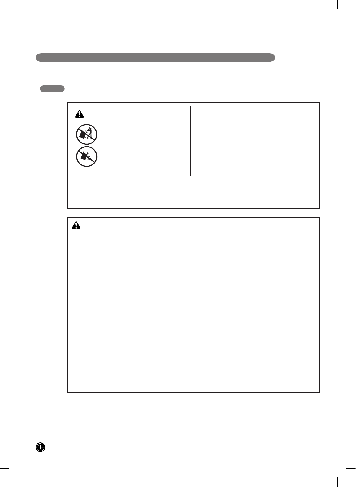
WARNING!
• DO NOT step or sit on the door. Install the Anti-
Tip Bracket packed with range.
- The range could be tipped and injury might result
from spilled hot liquid, food, or the range itself.
- If the range is pulled away from the wall for
cleaning, service, or any other reason, ensure that
the Anti-Tip Device is properly reengaged when the
range is pushed back against the wall.
All ranges can tip and injury could result. To prevent
accidental tipping of the range, attach an approved
Anti-Tip device to the wall. (See “INSTALLING THE
ANTI-TIP DEVICE” in this manual.) To check if the
device is installed and engaged properly, carefully tip
the range forward. The Anti-Tip device should engage
and prevent the range from tipping over.
If you pull the range out from the wall for any reason,
make sure the Anti-Tip device is engaged when you
push the range back against the wall.
WARNING!
• ALL RANGES CAN TIP
• INJURY TO PERSONS COULD
RESULT
• INSTALL ANTI-TIP DEVICES
PACKED WITH RANGE
• SEE INSTALLATION
INSTRUCTIONS
5
ENGLISH
INSTA L L ATION INSTRU C T I O N S
READ ALL INSTRUCTIONS BEFORE INSTALLATION
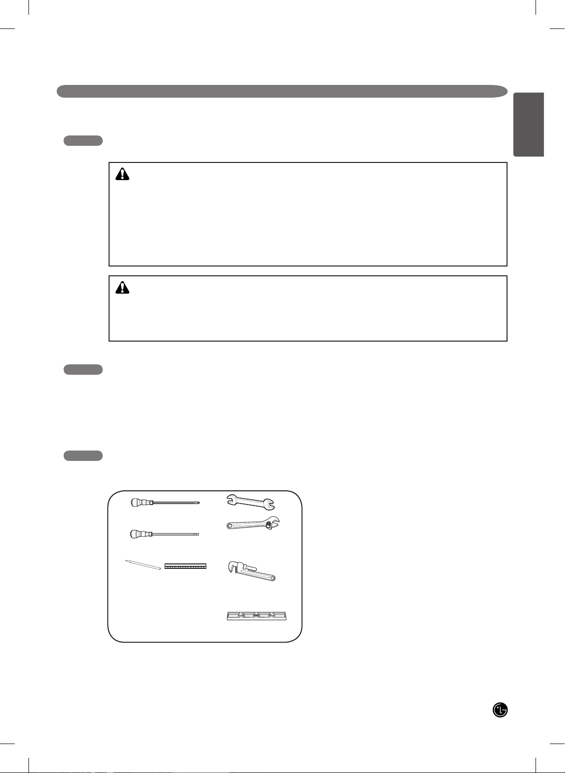
TOOLS YOU WILL NEED MATERIALS YOU MAY NEED
• Gas line shut-off valve
• Pipe joint sealant that resists action of natural and LP gases.
• Flexible metal appliance connector (3/4” or 1/2” NPT x 1/2”
I.D.)
Never use an old connector when installing a new range.
• Flare union adapter for connection to gas supply line (3/4” or
1/2” NPT x 1/2” I.D.)
• Flare union adapter for connection to pressure regulator on
range (1/2” NPT x 1/2” I.D.)
• Liquid leak detector or soapy water.
• Lag bolt or 1/2” O.D. sleeve anchor (for concrete floors only).
PREPARING FOR INSTALLATION
• This product must be installed by a licensed plumber or
gas fitter.
• When using ball type gas shut-off valves, they shall be
the T-handle type.
• When using a flexible gas connector, it must not exceed
3 feet in length.
IN THE COMMONWEALTH OF MASSACHUSETTS
Phillips screwdriver
Flat-blade screwdriver
Pencil and ruler
Pipe wrench(2)
(one for support)
Open-end or
adjustable wrench
Level
• If a 30” clearance between cooking surface and
overhead combustible material or metal cabinets
cannot be maintained, protect the underside of
the cabinets above the cooktop with not less than
1/4” insulating millboard covered with sheet metal
not less than 0.0122” thick. Clearance between
the cooking surface and protected cabinets MUST
NEVER BE LESS THAN 24 INCHES.
• The vertical distance from the plane of the cooking
surface to the bottom of adjacent overhead
cabinets extending closer than 1” to the plane of
the range sides must not be less than 18”. (See
the Dimensions and Clearances illustration in this
manual.)
• Items of interest to children should not be stored
in cabinets above a range or on the backsplash of
a range—children climbing on the range to reach
items could be seriously injured.
• DO NOT attempt to operate the oven of this range
during a power failure.
WARNING!
INSTALLATION SAFETY INSTRUCTIONS (continued)
CAUTION
6
INSTA L L ATION INSTRU C T I O N S
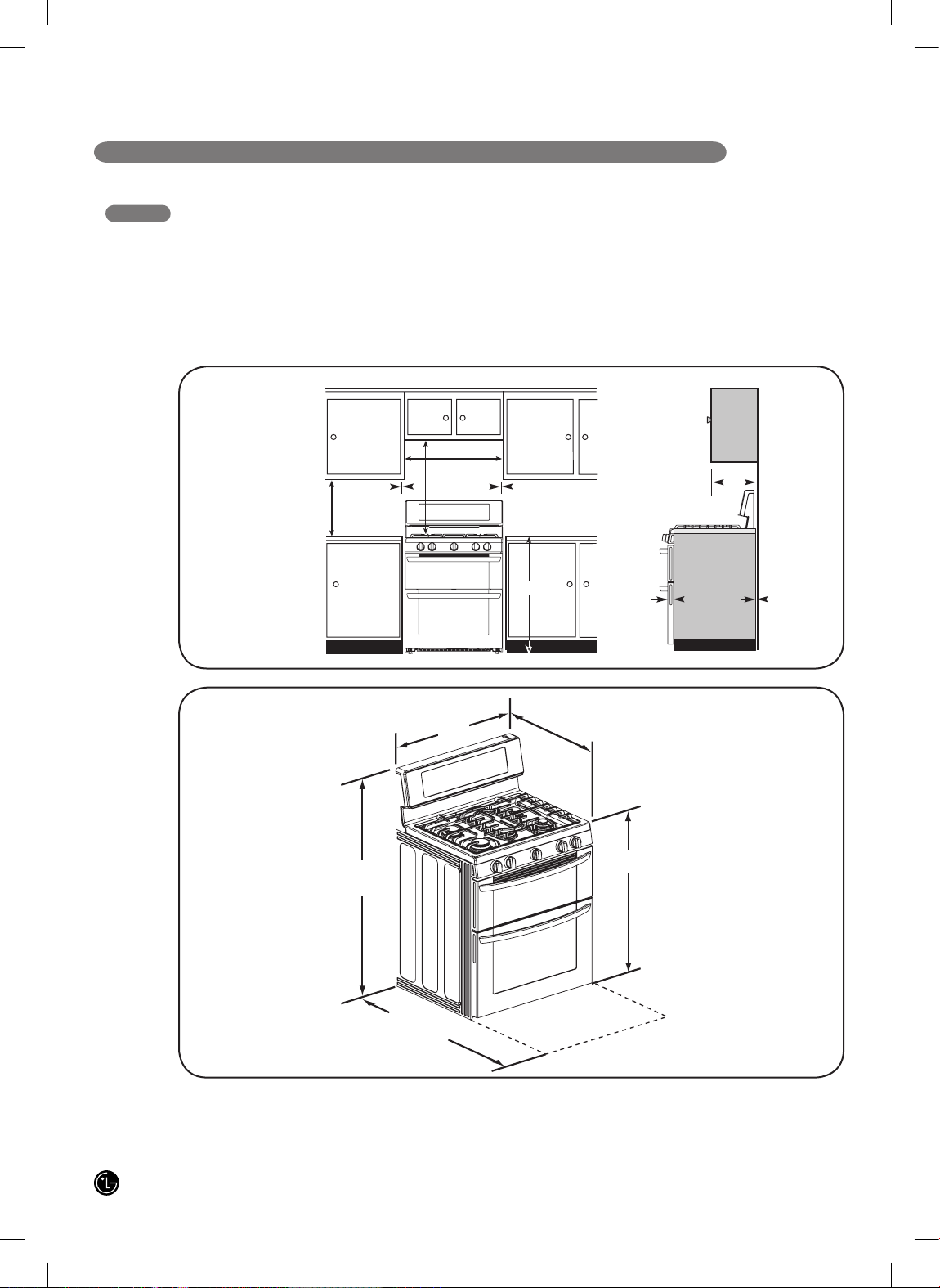
Provide proper clearances between the range and
adjacent combustible surfaces. These dimensions must
be met for safe use of your range. The location of the
electrical outlet and pipe opening (see “GAS PIPE AND
ELECTRICAL OUTLET LOCATIONS”) may be adjusted to
meet specific requirements.
The range may be placed with 0” clearance (flush) at the
back wall.
DIMENSIONS AND CLEARANCES
DIMENSIONS
Height
Depth with door open.
Depth with door closed (includes door handle)
INSTALLATION
CLEARANCES
Minimum to
cabinets on
either side
of the range
18”
5”
30”
30”
5”
36”
1/4”
13”
0”
Minimum
clearance to
left wall
Minimum clearance to
right wall
Front edge of
the range side
panel forward
from cabinet
To cabinets
below cooktop
and at the
range back
Maximum
depth for
cabinets above
coutertops
Minimum
30”
28
3
/
4”
47
7
/
16”
47
1
/
4”
36” ± 1/4”

7
ENGLISH
INSTA L L ATION INSTRU C T I O N S
Do not locate your range where it may be subject to
strong drafts. Any openings in the floor or wall behind
the range should be sealed. Make sure the openings
around the base of the range that supply fresh air
for combustion and ventilation are not blocked by
carpeting or woodwork.
Your range, like many other household units, is heavy and
can be installed on soft floor coverings such as cushioned
vinyl or carpeting. Use care when moving the range on
this type of flooring.
It is recommended that the following simple and
inexpensive instructions be followed to protect your floor.
This appliance must not be installed with a ventilation
system that blows air downward toward the range.
This type of ventilation system may cause ignition and
combustion problems with the gas cooking appliance
resulting in personal injury or unintended operation.
When the floor covering ends at the front of the range,
the area that the range will be installed on should be
built up with plywood to the same level or higher than the
floor covering. This will allow the range to be moved for
cleaning and servicing, as well as proper air flow to the
range.
Also, make sure the floor covering can resist 180°F (82°
C). See the "INSTALLATION SAFETY INSTRUCTIONS"
(included in this manual).
Make sure the wall coverings around your range can
resist the heat generated (up to 200°F/93°C) by the range.
See the "INSTALLATION SAFETY INSTRUCTIONS"
(included in this manual).
LOCATION
8
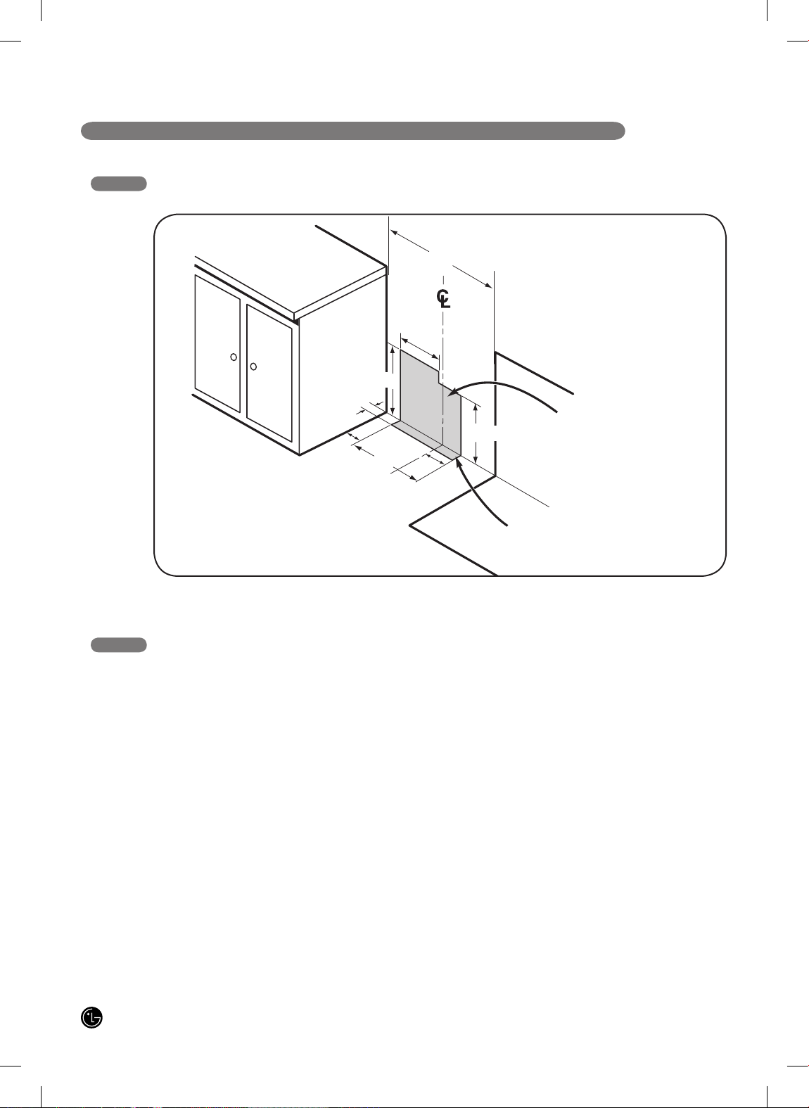
INSTA L L ATION INSTRU C T I O N S
GAS PIPE AND ELECTRICAL OUTLET LOCATIONS
Your range is designed to operate at a pressure of
5” of water column on natural gas or 10” of water
column on LP.
Make sure you are supplying your range with the type of
gas for which it is configured.
This range is convertible for use on natural or LP gas.
When using this range on LP gas, conversion must be
made by a qualified LP installer before attempting to
operate the range.
For proper operation, the pressure of natural gas supplied
to the regulator must be between 5” and 13” of water
column.
For LP gas, the pressure supplied to the regulator must be
between 10” and 13” of water column. When checking for
correct operation of the regulator, the inlet pressure must
be at least 1” more than the operating (manifold) pressure
as given above.
The pressure regulator located at the inlet of the range
must remain in the supply line regardless of which type of
gas is being used.
A flexible metal appliance connector used to connect the
range to the gas supply line should have an I.D. of 5/8”
and a max of 5ft. In Canada, flexible connectors must be
single wall metal connectors less than 6 feet in length.
1. PROVIDE ADEQUATE GAS SUPPLY
14
5
/
16
”
2”
3”
30”
9
1
/
16
”
11
”
8
19
/
32
3
/
32
”
2
3
/
8
”
Recommended area for 120V outlet
on rear wall and area for through-
the wall connection of pipe stub and
shut-off valve.
Recommended area for through-
the floor connection of pipe stub
and shut-off valve.
30”
9
ENGLISH
INSTA L L ATION INSTRU C T I O N S
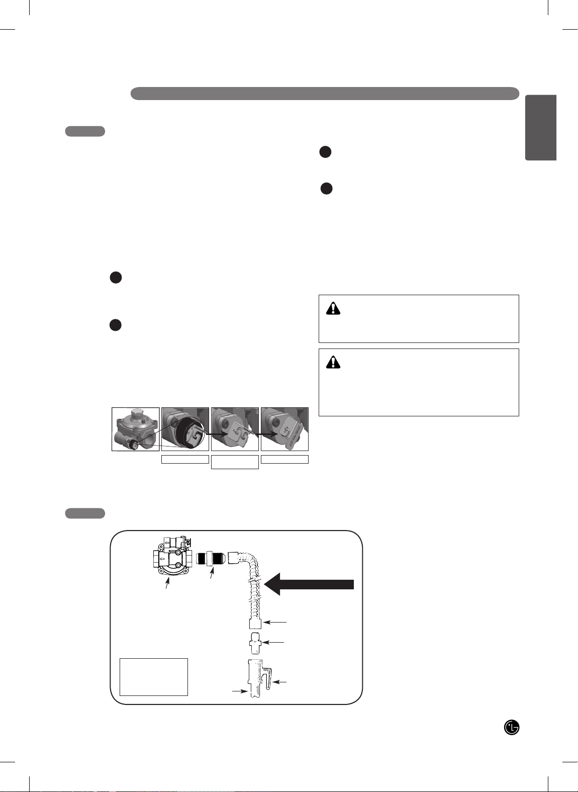
FLEXIBLE CONNECTOR HOOKUP
Pressure regulator
Installer: Inform the
consumer of the
location of the gas
shut-off valve
Adapter
Adapter
Gas shut-off valve
1/2” or 3/4”
Gas pipe
Flex connector
(6 ft. max.)
Gas Flow into Range
Shut off the range gas supply valve before removing
the old range and leave it off until the new hook-up
has been completed.
Because hard piping restricts movement of the range,
the use of a CSA International-certified flexible metal
appliance connector should be used unless local codes
require a hard-piped connection.
NEVER reuse an old connector when installing a new
range.
To protect against gas leaks, use a qualified pipe joint
sealant on all external threads.
Install male 1/2” or 3/4” flare union adapter to the NPT
internal thread of the manual shut-off valve, taking
care to back-up the shut-off valve to keep it from
turning.
Install male 1/2” flare union adapter to the 1/2” NPT
internal thread at inlet of pressure regulator. Use a
backup wrench on the pressure regulator fitting to
prevent damage.
Connect a flexible metal appliance connector to
the adapter on the range. Position range to permit
connection at the shut-off valve.
When all connections have been made, be sure all
range controls are in the off position and turn on the
main gas supply valve. Gas leaks may occur in your
system and result in a dangerous situation. Gas leaks
may not be detected by smell alone.
Check all gas connection joints and fittings for leaks
with a non-corrosive leak detection fluid, then wipe off.
Gas suppliers recommend you purchase and install
an UL approved gas detector. Install and use in
accordance with Installation instructions.
2. CONNECT THE RANGE TO GAS
A
C
B
D
DO NOT USE A FLAME TO CHECK FOR GAS
LEAKS.
WARNING!
Isolate the range from the gas supply system by
closing its individual shut-off valve during any pressure
testing of the gas supply system at test pressures
equal to or less than 1/2” psig(3.5kPa).
WARNING!
In a emergency situation or if you want to shut off
the gas suppluy, remove the packing rubber from the
regulator in the backside, and then close the regulator's
valve by positioning the lever as shown in the figure.
Lever’s open position Lever’s open position
(without rubber O-ring)
Lever’s close position
10
INSTA L L ATION INSTRU C T I O N S
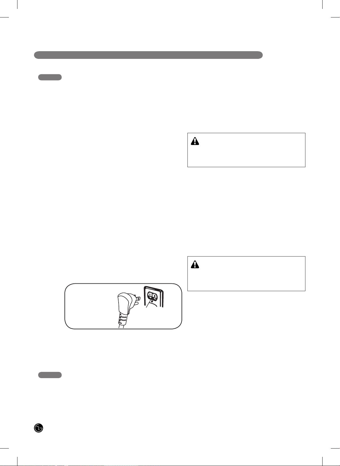
GROUNDING
IMPORTANT: FOR PERSONAL SAFETY, THIS APPLIANCE MUST BE PROPERLY GROUNDED.
ELECTRICAL REQUIREMENTS
120 Volt, 60 Hertz, properly grounded dedicated circuit protected by a 15 or 20 Amp circuit breaker, or slow blow fuse.
3. ELECTRICAL CONNECTIONS
The power cord of this appliance is equipped with a 3-prong
(grounding) plug which mates with a standard 3-prong
grounding wall receptacle to minimize the possibility of electric
shock hazard from this appliance.
The customer should have the wall receptacle and circuit
checked by a qualified electrician to make sure the receptacle
is properly grounded.
Where a standard two-prong wall receptacle is encountered,
it is the personal responsibility and obligation of the customer
to have it replaced with a properly grounded three-prong wall
receptacle.
DO NOT, UNDER ANY CIRCUMSTANCES, CUT OR
REMOVE THE THIRD (GROUND) PRONG FROM THE
POWER CORD.
A word about GFCI’s – GFCI’s are not required or
recommended for gas range receptacles.
Ground Fault Circuit Interrupters (GFCI’s) are devices that
sense leakage of current in a circuit and automatically switch
off power when a threshold leakage level is detected. These
devices must be manually reset by the consumer. The
National Electrical Code requires the use of GFCI’s in kitchen
receptacles installed to serve countertop surfaces.
Performance of the range will not be affected if operated on a
GFCI-protected circuit but occasional nuisance can occur.
DO NOT use an adapter plug because disconnecting of the
power cord places undue strain on the adapter and leads to
eventual failure of the adapter ground terminal.
The installation of appliances designed for mobile home
installation must conform with the Manufactured Home
Construction and Safety Standard, Title 24 CFR, Part 3280
(formerly the Federal Standard for Mobile Home Construction
and Safety, Title 24, HUD, Part 280) or, when such standard
is not applicable, the Standard for Manufactured Home
Installations, latest edition (Manufactured Home Sites,
Communities and Set-Ups), ANSI A225.1, latest edition, or
with local codes. In Canada, mobile home installation must
be in accordance with the current CAN/CSA Z240/MH Mobile
Home Installation Code.
Ensure proper ground
exists before use
PREFERRED
METHOD
Seal any openings in the wall and floor after electrical and gas supplies are completed.
4. SEAL THE OPENINGS
CAUTION:
The customer should have the circuit checked by a
qualified electrician to make sure the receptacle is
properly grounded.
WARNING!
POWER MUST BE DISCONNECTED BEFORE
SERVICING THE APPLIANCE. FAILURE TO DO SO
CAN RESULT IN DEATH OR ELECTRICAL SHOCK.
 Loading...