


 Loading...
ENGLISH
OWNER’S MANUAL
LED LCD MONITOR
Please read this manual carefully before operating your set and retain it for future reference.
LED LCD MONITOR MODELS
E1951S E1951T E1951C E2251VR E2251VQ
E2051S E2051T E2051C E2351VR E2351VQ
E2251S E2251T E2251C
E2351T
E2351TC
www.lg.com

ENGLISH
2 TABLE OF CONTENTS
CONTENTS
3 |
ASSEMBLING AND |
|
21 |
SPECIFICATIONS |
|
|
PREPARING |
26 |
Preset Modes (Resolution) |
||
3 |
Unpacking |
||||
27 |
- HDMI Video Timing |
||||
4 |
Parts and buttons |
27 |
Indicator |
||
6 |
Setting up the Monitor |
|
|
|
|
6 |
- Assembling the Stand Body and Base |
|
28 |
PROPER POSTURE |
|
7 |
- Mounting on a table |
||||
28 |
Proper posture for using the Monitor. |
||||
8 |
- Detaching the Stand Base and the |
||||
|
Stand Body |
|
29 |
|
|
9 |
- Mounting on a wall |
LICENSES |
|||
11 USING THE MONITOR
11Connecting to a PC
11- D-SUB connection
12- DVI-D connection
13- HDMI connection
14CUSTOMIZING SETTINGS
14Accessing The Main Menus
15Customizing Settings
15- MENU Settings
16- SUPER ENERGY SAVING Settings
17- SUPER+ RESOLUTION Settings
17- VOLUME Settings (Only supported in HDMI)
18- DUAL MONITOR Settings
18- DUAL WEB Settings
19TROUBLESHOOTING
ASSEMBLING AND PREPARING 3
ASSEMBLING AND PREPARING
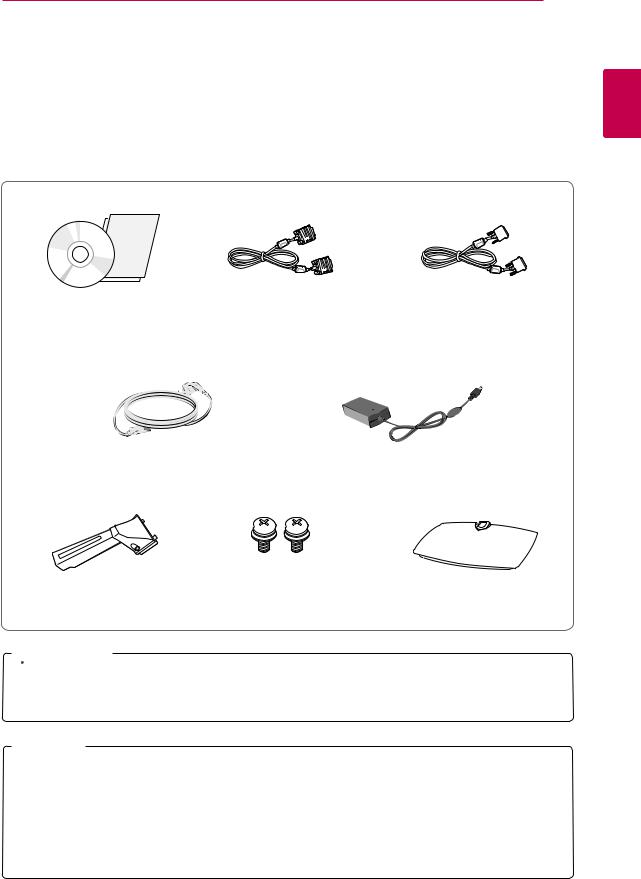
Unpacking
Check your product box for the following items. If there are any missing accessories, contact the local dealer where you purchased your product. The illustrations in this manual may differ from the actual product and accessories.
ENGLISH
CD(Owner's Manual) / |
D-SUB Cable |
DVI-D Cable |
Card |
(This signal cable may be attached |
(In some countries, this |
|
to this product before shipping out.) |
accessory may not be provided.) |
Power Cord |
AC-DC Adapter |
Stand Body |
Screws for Assembly |
|
2 EA |
Stand Base |
 CAUTION
yyDo not use any unapproved accessories to ensure the safety and product life span.
yyAny damages or injuries by using unapproved accessories are not covered by the warranty.
 NOTE
NOTE
yyThe accessories supplied with your product may vary depending on the model.
yyProduct specifications or contents in this manual may be changed without prior notice due to upgrade of product functions.
yyUser should use shielded signal interface cables (RGB cable/ DVI-D cable) with ferrite cores to maintain standard compliance for the product.
4 ASSEMBLING AND PREPARING
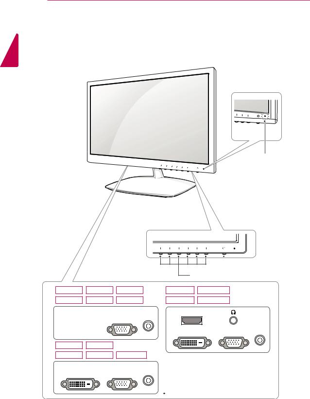
Parts and buttons
ENGLISH
Power Indicator yyLighting On: Turned on yyLighting Off: Turned off


 (Power Button)
Button ("CUSTOMIZING SETTINGS" on page 14)
E1951S |
E2051S |
E2251S |
E2251VR |
E2251VQ |
E1951C |
E2051C |
E2251C |
E2351VR |
E2351VQ |
DC-IN /
D-SUB
HDMI
DC-IN /
DVI-D D-SUB
E1951T |
E2051T |
|
E2251T |
E2351T |
E2351TC |
DC-IN /
DVI-D D-SUB
 Connection panel (See p.11)
|
|
ASSEMBLING AND PREPARING 5 |
|
|
|
|
|
Button |
|
Description |
|
MENU |
Accesses the main menus.(See p.15) |
||
|
|
|
|
Left First Button |
OSD LOCKED/ |
This function allows you to lock the current control settings, so |
|
|
UNLOCKED |
that they cannot be inadvertently changed. |
|
|
|
Press and hold the Left First Button for several seconds. |
|
|
|
The message "OSD LOCKED" should appear. |
|
|
|
You can unlock the OSD controls at any time by pushing the |
|
|
|
Left First Button for several seconds. The message "OSD |
|
|
|
UNLOCKED" should appear. |
|
SUPER+ RESOLUTION |
Use this button to enter the SUPER+ RESOLUTION menu. For more information.(See p.17) |
||
DUAL |
Use this button to enter the DUAL menu. |
||
|
For more information.(See p.18) |
||
AUTO |
Press the AUTO button on the MONITOR SETUP OSD menu to automatically adjust the |
||
|
screen. |
|
|
|
(Only supported in Analog Mode) |
||
|
The best display mode |
|
|
|
E1951S/ E1951T/ |
1366 x 768 |
|
|
E1951C |
|
|
|
E2051S/ E2051T/ |
1600 x 900 |
|
|
E2051C |
|
|
|
E2251S/ E2251T/ |
1920 x 1080 |
|
|
E2251C/ E2251VR/ |
|
|
|
E2251VQ/ E2351TC |
|
|
|
E2351T/ E2351VR |
|
|
|
E2351VQ |
|
|
VOLUME (Only HDMI mode) E2251VR/ E2351VR/ E2251VQ/ E2351VQ
|
Adjust the volume of the Monitor.(See p.17) |
|
|
|
|
INPUT |
You can choose the input signal. |
|
|
yy When two input signals are at least are connected, you can select the input signal |
|
|
(D-SUB/ DVI-D/ HDMI) you want. |
|
|
yy When only one signal is connected, it is automatically detected. The default setting is |
|
|
D-SUB. |
|
EXIT |
Exit the OSD(On Screen Display). |
|
(Power Button) |
Turns the power on or off. |
|
|
Power Indicator |
The power indicator stays blue if the display is running |
|
|
properly (On Mode). If the display is in Sleep Mode, the power |
|
|
indicator blinks blue. |
ENGLISH

ENGLISH
6 ASSEMBLING AND PREPARING
Setting up the Monitor
Assembling the Stand Body and Base
1Place the Monitor with the screen side down on a flat and cushioned surface.
 WARNING
yyIf you do not fasten the screws, the monitor may fall, which may result in damage to the product.
4Check the direction of the Stand Base and assemble it with the Stand Body. Using a coin, turn the screw clockwise to secure the
Stand Base.
2Attach the Stand Body from the Monitor.
Insert the two Lockers of the Stand Body right into the groove of the Monitor head and secure
them by pressing the left and right bottom sides.
Locker
3Secure the Stand Body the monitor using 2 screws.
Stand Body
Stand Base
Coin
 CAUTION
yyThis illustration depicts the general type of connection. Your monitor may differ from the items shown in the picture.
yyDo not carry the product upside down holding only the stand base. The product may fall and get damaged or injure your foot.
yyApplying excessive force when fastening screws may cause damage to the monitor. Damage caused in this way will not be covered by the product warranty.
ASSEMBLING AND PREPARING 7
Mounting on a table |
WARNING |
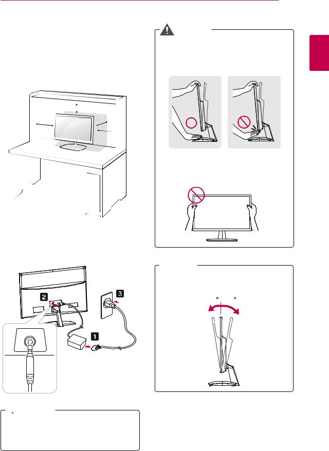
1Lift and tilt the Monitor into its upright position on a table.
Leave a 10 cm (minimum) space from the wall for proper ventilation.
10 cm 
10 cm
10 cm
10 cm 
When you adjust the angle, do not hold the bottom of the Monitor frame as shown on the following illustration, as it may injure your fingers.
Do not touch or press the screen when adjusting the angle of the monitor.
ENGLISH
2 Connect the AC-DC Adapter and Power Cord to a wall outlet.
 NOTE
NOTE
Tilt from +15 to -5 degrees up or down to adjust the angle of the Monitor to suit your view.
- 5 15
DC-IN /
Front |
Rear |
 CAUTION
Disconnect the power cord first, and then move or install the Monitor. Otherwise electric
shock may occur.
ENGLISH
8 ASSEMBLING AND PREPARING
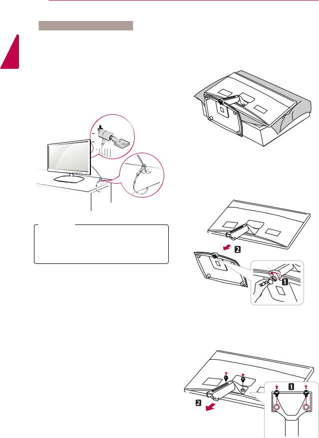
Using the Kensington security system
The Kensington security system connector is located at the back of the Monitor. For more information of installation and using, refer to the manual supplied with the Kensington security system or visit http://www.kensington.com.
Connect the Kensington security system cable between the Monitor and a table.
 NOTE
NOTE
The Kensington security system is optional. You can obtain it from most electronics stores.
Detaching the Stand Base and the
Stand Body
1Place the Monitor with the screen side down on a flat and cushioned surface.
2Using a coin, turn the screw in the Stand Base counterclockwise. Detach the Stand Base from the Stand Body.
3Remove the 2 screws and detach the Stand Body from the monitor.
|
ASSEMBLING AND PREPARING 9 |
|||
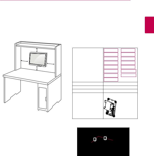
Mounting on a wall |
5 Please use a VESA standard as below. |
|||
For proper ventilation, allow a clearance of 10 cm |
yy784.8 mm (30.9 inch) and under |
|
||
* Wall Mount Pad Thickness : 2.6 mm |
||||
on each side and from the wall. Detailed |
||||
* Screw : Φ 4.0 mm x Pitch 0.7 mm x |
||||
instructions are available from your dealer, see the |
Length 10 mm |
|
||
optional Tilt Wall Mounting Bracket Installation and |
|
|||
yy787.4 mm (31.0 inch) and above |
|
|||
Setup Guide. |
|
|||
* Please use VESA standard wall mount pad |
||||
|
||||
|
and screws. |
|
|
|
10 cm |
Model |
E1951S |
E1951C |
|
|
|
E2051S |
E2051C |
|
10 cm |
|
E2251S |
E2251C |
|
10 cm |
|
E1951T |
E2251VR |
|
|
|
|||
10 cm |
|
E2051T |
E2351VR |
|
|
E2251T |
E2251VQ |
||
|
|
|||
|
|
E2351T |
E2351VQ |
|
|
|
E2351TC |
|
|
|
VESA (A x B) |
75 x 75 |
|
|
|
Screw Size |
M4 |
|
|
|
Number of screws |
4 |
|
|
|
Wall mount bracket |
RW120 |
|
|
|
(optional) |
|
|
|
ENGLISH
If intend to mount the Monitor to a wall, an optional third-party wall mount must be purchased.
When you install the Monitor using the wall mounting interface (optional parts), attach it carefully so it will not fall.
1Please use screws and a wall mount interface in accordance with VESA Standards.
2If you use screws longer than standard, the monitor might be damaged internally.
3If you use improper screws, the product might be damaged and drop from mounted position. In this case, LG Electronics is not responsible for it.
4VESA compatible only with respect to screw mounting interface dimensions and mounting screw specifications.
yyVESA (A x B)
B A
Loading...