


 Loading...
ThinkServer
User Guide
Machine Types: 1098, 1100, 1105, and 1106
Note:
Before using this information and the product it supports, be sure to read and understand the following:
•The Important Notices that came with your product
•The Safety Information and the Warranty and Support Information at http://www.lenovo.com/support
•Appendix A “Notices” on page 83
First Edition (May 2011)
© Copyright Lenovo 2011.
LENOVO products, data, computer software, and services have been developed exclusively at private expense and are sold to governmental entities as commercial items as defined by 48 C.F.R. 2.101 with limited and restricted rights to use, reproduction and disclosure.
LIMITED AND RESTRICTED RIGHTS NOTICE: If products, data, computer software, or services are delivered pursuant a General Services Administration “GSA” contract, use, reproduction, or disclosure is subject to restrictions set forth in Contract No. GS-35F-05925.

Contents
Safety information . . . . . . . . . . |
iii |
Chapter 1. General information. . . . . |
1 |
Introduction . . . . . . . . . . . . . . . . . |
1 |
Notices and statements in the document . . . . . |
1 |
Related documentation . . . . . . . . . . . . |
2 |
Chapter 2. Server setup road map . . . 3
Chapter 3. Product overview . . . . . . |
5 |
What is included with your server . . . . . . . . |
5 |
Features and specifications. . . . . . . . . . . |
5 |
Software programs . . . . . . . . . . . . . . |
7 |
EasyStartup . . . . . . . . . . . . . . . |
7 |
Reliability, availability, and serviceability . . . . |
7 |
Chapter 4. Locating parts, controls, |
|
and connectors . . . . . . . . . . . . . |
9 |
Front view . . . . . . . . . . . . . . . . . |
9 |
Rear view. . . . . . . . . . . . . . . . . . |
9 |
Locating parts on the system board . . . . . . |
11 |
Internal components . . . . . . . . . . . . |
12 |
Internal drives . . . . . . . . . . . . . . . |
13 |
Machine type and model label . . . . . . . . |
13 |
Chapter 5. Installing, removing, or |
|
replacing hardware . . . . . . . . . . |
15 |
Guidelines . . . . . . . . . . . . . . . . |
15 |
Basic guidelines . . . . . . . . . . . . |
15 |
System reliability guidelines . . . . . . . . |
16 |
Handling static-sensitive devices . . . . . |
16 |
Removing the server cover . . . . . . . . . . |
17 |
Removing and reinstalling the front bezel . . . . |
18 |
Installing, removing, or replacing optional hardware |
|
devices . . . . . . . . . . . . . . . . . |
20 |
Installing or replacing a PCI card . . . . . . |
20 |
Installing or removing the Ethernet card . . . |
23 |
Installing or removing a memory module. . . |
24 |
Installing or replacing the optical drive . . . |
26 |
Replacing the primary hard disk drive . . . . |
28 |
Installing or replacing the secondary hard disk |
|
drive . . . . . . . . . . . . . . . . . |
31 |
Installing, removing, or replacing hardware |
|
devices . . . . . . . . . . . . . . . . . |
34 |
Replacing the power supply assembly . . . |
35 |
Replacing the heat sink and fan assembly . . |
37 |
Replacing the front audio and USB |
|
assembly . . . . . . . . . . . . . . . |
39 |
Replacing the front fan assembly . . . . . |
40 |
Replacing the rear fan assembly . . . . . . |
42 |
Replacing the microprocessor . . . . . . . |
44 |
Replacing the system board battery . . . . |
47 |
Completing the parts replacement . . . . . . . |
48 |
Connecting the cables . . . . . . . . . . |
49 |
Turning on the server . . . . . . . . . . |
49 |
Turning off the server . . . . . . . . . . |
50 |
Connecting external devices . . . . . . . |
50 |
Updating the server configuration . . . . . |
51 |
Installing security features . . . . . . . . . . |
51 |
Integrated cable lock . . . . . . . . . . |
51 |
Padlock . . . . . . . . . . . . . . . |
51 |
Password protection . . . . . . . . . . |
51 |
Chapter 6. Configuring the server . . |
53 |
Using the Setup Utility program . . . . . . . . |
53 |
Starting the Setup Utility program . . . . . |
53 |
Introduction of the BIOS items. . . . . . . |
53 |
Viewing and changing settings . . . . . . |
66 |
Using passwords . . . . . . . . . . . . |
66 |
Enabling or disabling a device . . . . . . . |
68 |
Selecting a startup device . . . . . . . . |
69 |
Exiting from the Setup Utility program. . . . |
69 |
Configuring RAID. . . . . . . . . . . . . . |
69 |
RAID level. . . . . . . . . . . . . . . |
69 |
Configuring the system BIOS to enable SATA |
|
RAID functionality. . . . . . . . . . . . |
70 |
Creating RAID volumes . . . . . . . . . |
70 |
Deleting RAID volumes . . . . . . . . . |
70 |
Resetting disks to non-RAID . . . . . . . |
71 |
Updating the firmware. . . . . . . . . . . . |
71 |
Using the EasyUpdate Firmware Updater |
|
program . . . . . . . . . . . . . . . |
71 |
Using the ThinkServer EasyStartup program . . . |
72 |
Updating system programs. . . . . . . . . . |
72 |
Using system programs . . . . . . . . . |
72 |
Updating (flashing) the BIOS from a disc. . . |
73 |
Updating (flashing) the BIOS from your |
|
operating system . . . . . . . . . . . . |
73 |
Recovering from a POST/BIOS update |
|
failure . . . . . . . . . . . . . . . . |
74 |
Chapter 7. Troubleshooting and |
|
diagnostics . . . . . . . . . . . . . . |
75 |
Basic troubleshooting . . . . . . . . . . . . |
75 |
General problems. . . . . . . . . . . . |
75 |
© Copyright Lenovo 2011 |
i |
EasyStartup problems . . . . . . . . . . |
76 |
PC-Doctor for DOS . . . . . . . . . . . . . |
76 |
Creating a diagnostic disc . . . . . . . . |
76 |
Running the diagnostic program from a |
|
diagnostic disc . . . . . . . . . . . . . |
76 |
Chapter 8. Information resources . . |
79 |
Safety and Warranty . . . . . . . . . . . . |
79 |
Lenovo Web site (http://www.lenovo.com) . . . . |
79 |
Lenovo Support Web site . . . . . . . . . . |
79 |
Chapter 9. Help and service . . . . . |
81 |
Using the documentation . . . . . . . . . . |
81 |
Calling for service . . . . . . . . . . . . . |
81 |
Using other services . . . . . . . . . . . . |
82 |
Purchasing additional services . . . . . . . . |
82 |
Appendix A. Notices . . . . . . . . . |
83 |
Trademarks . . . . . . . . . . . . . . . . |
84 |
Polyvinyl Chloride (PVC) cable and cord notice . . |
84 |
Recycling information . . . . . . . . . . . . |
84 |
Battery return program. . . . . . . . . . |
85 |
Requirements for Batteries Containing |
|
Perchlorate . . . . . . . . . . . . . . |
85 |
Important information for the European Directive |
|
2002/96/EC . . . . . . . . . . . . . . . . |
86 |
Particulate contamination . . . . . . . . . . |
89 |
Restriction of Hazardous Substances Directive |
|
(RoHS) . . . . . . . . . . . . . . . . . . |
90 |
China RoHS . . . . . . . . . . . . . . |
91 |
Turkish statement of compliance . . . . . . |
91 |
German Ordinance for Work gloss statement. . . |
92 |
Electronic emission notices. . . . . . . . . . |
92 |
Federal Communications Commission (FCC) |
|
Statement. . . . . . . . . . . . . . . |
92 |
Index. . . . . . . . . . . . . . . . . . |
95 |
ii ThinkServer User Guide

Safety information
Before installing this product, read the Safety Information.
© Copyright Lenovo 2011 |
iii |
Important: Each caution and danger statement in this document is labeled with a number. This number is used to cross reference an English-language caution or danger statement with translated versions of the caution or danger statement in the Safety Information manual. For example, if a caution statement is labeled “Statement 1,” translations for this caution statement are in the Safety Information manual under “Statement 1.”
Be sure to read and understand all caution and danger statements in this document before you perform the procedures. Read and understand any additional safety information that comes with the server or an optional device before you install, remove, or replace the device.
Statement 1
DANGER
Electrical current from power, telephone, and communication cables is hazardous.
To avoid a shock hazard:
•Do not connect or disconnect any cables or perform installation, maintenance, or reconfiguration of this product during an electrical storm.
•Connect all power cords to a properly wired and grounded electrical outlet.
•Connect to properly wired outlets any equipment that will be attached to this product.
•When possible, use one hand only to connect or disconnect signal cables.
•Never turn on any equipment when there is evidence of fire, water, or structural damage.
•Disconnect the attached power cords, telecommunications systems, networks, and modems before you open the device covers, unless instructed otherwise in the installation and configuration procedures.
•Connect and disconnect cables as described in the following table when installing, moving, or opening covers on this product or attached devices.
To Connect: |
To Disconnect: |
||
1. |
Turn everything OFF. |
1. |
Turn everything OFF. |
2. |
First, attach all cables to devices. |
2. |
First, remove power cords from outlet. |
3. |
Attach signal cables to connectors. |
3. |
Remove signal cables from connectors. |
4. |
Attach power cords to outlet. |
4. |
Remove all cables from devices. |
5. |
Turn device ON. |
|
|
|
|
|
|
iv ThinkServer User Guide

Statement 2
CAUTION:
When replacing the lithium battery, use only the battery recommended by the manufacturer. If your system has a module containing a lithium battery, replace it only with the same module type made by the same manufacturer. The battery contains lithium and can explode if not properly used, handled, or disposed of.
Do not:
•Throw or immerse into water
•Heat to more than 100°C (212°F)
•Repair or disassemble
Dispose of the battery as required by local ordinances or regulations.
Statement 3
CAUTION:
When laser products (such as CD-ROMs, DVD drives, fiber optic devices, or transmitters) are installed, note the following:
•Do not remove the covers. Removing the covers of the laser product could result in exposure to hazardous laser radiation. There are no serviceable parts inside the device.
•Use of controls or adjustments or performance of procedures other than those specified herein might result in hazardous radiation exposure.
 DANGER
Some laser products contain an embedded Class 3A or Class 3B laser diode. Note the following.
Laser radiation when open. Do not stare into the beam, do not view directly with optical instruments, and avoid direct exposure to the beam.
© Copyright Lenovo 2011 |
v |
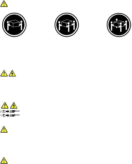
Statement 4
≥ 18 kg (39.7 lb) |
≥ 32 kg (70.5 lb) |
≥ 55 kg (121.2 lb) |
< 32 kg (70.5 lb) |
< 55 kg (121.2 lb) |
< 100 kg (220.5 lb) |
CAUTION:
Use safe practices when lifting.
Statement 5
CAUTION:
The power control button on the device and the power switch on the power supply do not turn off the electrical current supplied to the device. The device also might have more than one power cord. To remove all electrical current from the device, ensure that all power cords are disconnected from the power source.
Statement 6
CAUTION:
If you install a strain-relief bracket option over the end of the power cord that is connected to the device, you must connect the other end of the power cord to an easily accessible power source.
Statement 7
CAUTION:
If the device has doors, be sure to remove or secure the doors before moving or lifting the device to avoid personal injury. The doors will not support the weight of the device.
vi ThinkServer User Guide
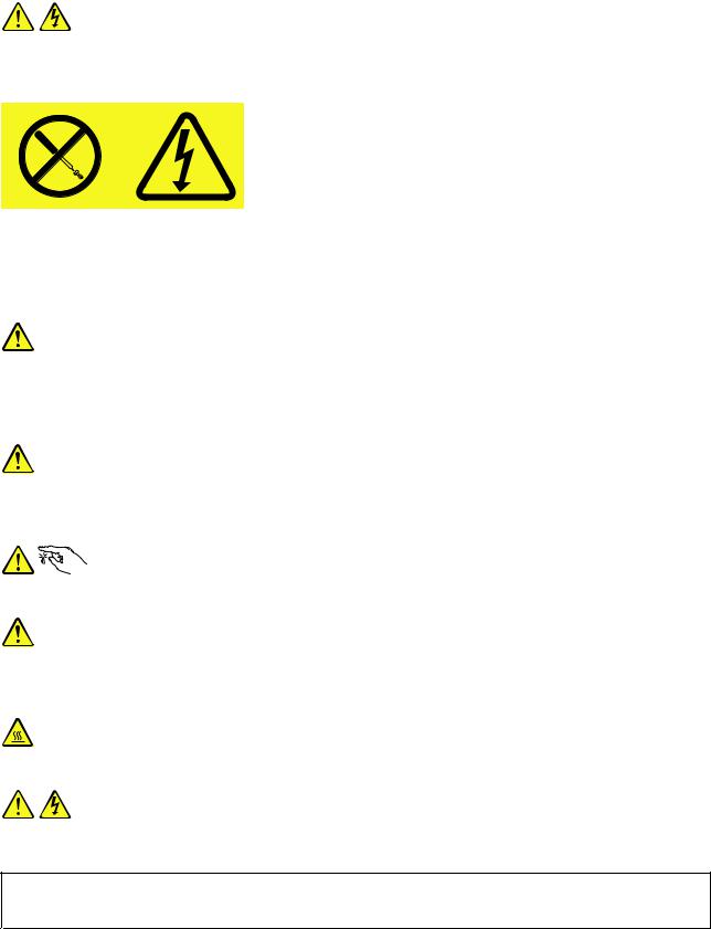
Statement 8
CAUTION:
Never remove the cover on a power supply or any part that has the following label attached.
Hazardous voltage, current, and energy levels are present inside any component that has this label attached. There are no serviceable parts inside these components. If you suspect a problem with one of these parts, contact a service technician.
Statement 9
CAUTION:
To avoid personal injury, disconnect the hot-swap fan cables before removing the fan from the device.
Statement 10
CAUTION:
The following label indicates sharp edges, corners, or joints nearby.
Statement 11
CAUTION:
The following label indicates a hot surface nearby.
Statement 12
DANGER
Overloading a branch circuit is potentially a fire hazard and a shock hazard under certain conditions. To avoid these hazards, ensure that your system electrical requirements do not exceed branch circuit protection requirements. Refer to the information that is provided with your device for electrical specifications.
© Copyright Lenovo 2011 |
vii |
Statement 13
CAUTION:
Make sure that the rack is secured properly to avoid tipping when the server unit is extended.
Statement 14
CAUTION:
Some accessory or option board outputs exceed Class 2 or limited power source limits and must be installed with appropriate interconnecting cabling in accordance with the national electric code.
Statement 15
CAUTION:
The power-control button on the device does not turn off the electrical current supplied to the device. The device also might have more than one connection to dc power. To remove all electrical current from the device, ensure that all connections to dc power are disconnected at the dc power input terminals.
Statement 16
CAUTION:
To reduce the risk of electric shock or energy hazards:
•This equipment must be installed by trained service personnel in a restricted-access location, as defined by the NEC and the latest edition of IEC 60950, The Standard for Safety of Information
Technology Equipment.
•Connect the equipment to a reliably grounded safety extra low voltage (SELV) source. An SELV source is a secondary circuit that is designed so that normal and single fault conditions do not cause the voltages to exceed a safe level (60 V direct current).
•The branch circuit overcurrent protection must be rated in accordance with local building codes.
•Use 16 American Wire Gauge (AWG) or 1.3 mm2 copper conductor only, not exceeding 3 meters in length.
•Torque the wiring-terminal screws to 12 inch-pounds (1.4 newton-meters).
•Incorporate a readily available approved and rated disconnect device in the field wiring.
Statement 17
CAUTION:
This product contains a Class 1M laser. Do not view directly with optical instruments.
viii ThinkServer User Guide
Statement 18
CAUTION:
Do not place any object on top of rack-mounted devices.
Statement 19
CAUTION:
Hazardous moving parts are nearby.
Statement 20
CAUTION:
The battery is a lithium ion battery. To avoid possible explosion, do not burn the battery. Exchange it only with the Lenovo-approved part. Recycle or discard the battery as instructed by local regulations.
© Copyright Lenovo 2011 |
ix |
x ThinkServer User Guide

Chapter 1. General information
This chapter provides some general information about your server.
This chapter contains the following topics:
•“Introduction” on page 1
•“Notices and statements in the document” on page 1
•“Related documentation” on page 2
Introduction
This user guide is for your Lenovo® ThinkServer® TS130 server (machine types 1098, 1100, 1105, and 1106). This document contains the following information:
•Setting up and cabling the server
•Starting and configuring the server
•Installing options and replacing customer replaceable units (CRUs)
•Solving problems
The server comes with the ThinkServer EasyStartup DVD to help you configure the hardware, install device drivers, and install the operating system.
The server comes with a limited warranty. For information about the terms of the warranty and getting service and assistance, see the Warranty and Support Information at http://www.lenovo.com/support.
To obtain the most up-to-date information about the server and other Lenovo products, go to: http://www.lenovo.com/thinkserver
Record information about the server in the following table. You will need these information when you register the server with Lenovo.
Product name |
ThinkServer TS130 |
Machine type |
1098, 1100, 1105, and 1106 |
Model number |
_____________________________________________ |
Serial number |
_____________________________________________ |
|
|
The model number and serial number are on labels on the top or on the bottom of the server.
Notices and statements in the document
The caution and danger statements that appear in this document are also in the multilingual Safety Information. Each caution and danger statement in this document is labeled with a number. This number is used to cross reference an English-language caution or danger statement with translated versions of the caution or danger statement in the Safety Information. See “Related documentation” on page 2 for detailed information about how to get the various documentation for your server.
The following notices and statements are used in this document:
• Note: These notices provide important tips, guidance, or advice.
© Copyright Lenovo 2011 |
1 |

•Important: These notices provide information or advice that might help you avoid problems or inconvenient situations.
•Attention: These notices indicate potential damage to programs, devices, or data. An attention notice is placed just before the instruction or situation in which damage could occur.
•Caution: These statements indicate situations that can be potentially hazardous to you. A caution statement is placed just before the description of a potentially hazardous procedure step or situation.
•Danger: These statements indicate situations that can be potentially lethal or extremely hazardous to you. A danger statement is placed just before the description of a potentially lethal or extremely hazardous procedure step or situation.
Related documentation
To view the documentation at http://www.lenovo.com/support, you need to have the Adobe Reader 5.0 program or later installed.
The following information provides general descriptions of the various documentation that came with your server and information about how to obtain all these documentation:
•Hardware Maintenance Manual: This document provides diagnostic information, parts listing, replacement procedures for all CRUs, and replacement procedures for other field replaceable units (FRUs) replaced by trained service personnel.
•Getting Started: This document provides general information about installing and configuring the server.
Note: This document is in Serbian Latin only.
•Important Notices: This document includes safety and legal notices that you are expected to read before using the server.
•Read Me First: This document directs you to the http://www.lenovo.com/support for complete warranty and support information.
•Safety Information: This document includes translations of all safety statements used in the ThinkServer documentation.
•Warranty and Support Information: This document includes the warranty statement and information about how to contact Lenovo Support.
You can obtain all the documentation in Portable Document Format (PDF) for your server from the Lenovo Support Web site at http://www.lenovo.com/support.
2 ThinkServer User Guide

Chapter 2. Server setup road map
This chapter provides a general road map to guide you through setting up your server.
The server setup procedure varies depending on the configuration of the server when it was delivered. In some cases, the server is fully configured and you just need to connect the server to the network and an electrical outlet, and then you can turn on the server. In other cases, the server needs to have hardware features installed, requires hardware and firmware configuration, and requires the operating system to be installed.
Table 1. Server setup road map
Task |
Where to find the information |
|
|
Unpack |
“What is included with your server” on page 5 |
|
|
Install hardware |
Chapter 5 “Installing, removing, or replacing hardware” on page 15 |
|
|
Connect the Ethernet cable |
“Rear view” on page 9 |
and power cord |
|
|
|
Turn on the server to verify |
“Turning on the server” on page 49 |
operation |
|
|
|
Review the BIOS settings |
“Starting the Setup Utility program” on page 53 |
and customize as needed |
|
|
|
Configure RAID |
“Configuring RAID” on page 69 |
|
|
Check for firmware updates |
“Updating the firmware” on page 71 |
|
|
Install the operating system |
“EasyStartup” on page 7 |
and basic drivers |
|
|
|
Install any additional drivers |
Refer to the instructions that came with the hardware option. |
needed for added features |
|
|
|
Configure Ethernet settings |
See the operating system help. This step is not required if the operating system was |
in the operating system |
installed using the ThinkServer EasyStartup program. |
|
|
Install applications |
Refer to the documentation that comes with the applications that you want to install. |
|
|
© Copyright Lenovo 2011 |
3 |
4 ThinkServer User Guide
Chapter 3. Product overview
This chapter provides information about the server package, features, specifications, and software programs.
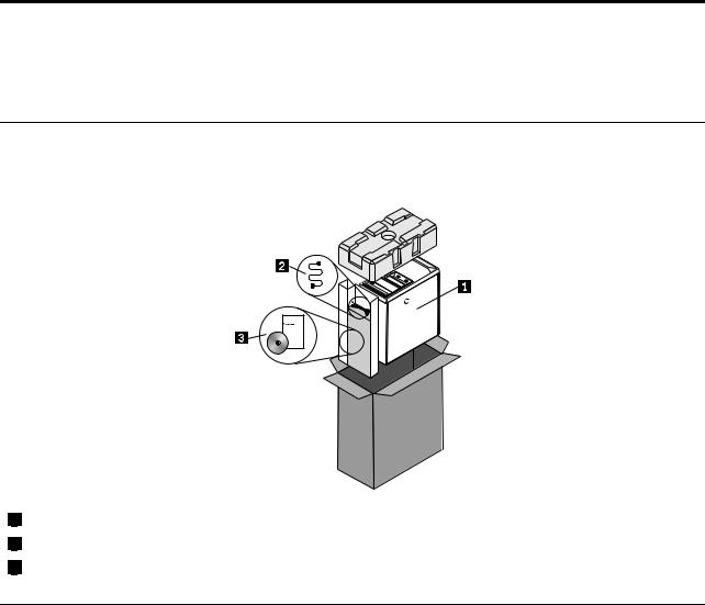
What is included with your server
The ThinkServer TS130 server package includes the server, a power cord, documentation, and software media.
1 |
Server |
2 |
Power cord |
3 |
Documentation and software media |
Features and specifications
The following table provides information about the features and specifications of the server. Depending on the server model, some features might not be available, or some specifications might not apply. For
information about your specific model, use the Setup Utility program. See “Using the Setup Utility program” on page 53.
© Copyright Lenovo 2011 |
5 |
Table 2. Features and specifications
Microprocessor(s): Support up to two Intel® Xeon® |
Expansion |
||
dual-core, quad-core, or hex-core microprocessors |
• Two optical drive bays |
||
(internal cache size varies by model type) |
|||
• Two hard disk drive bays |
|||
|
|||
For the specific type and speed information about the |
• Two PCI card slots |
||
microprocessor, use the Setup Utility program. See |
|||
• One PCI Express x1 card slot |
|||
“Using the Setup Utility program” on page 53. |
|||
|
|
||
For a list of supported microprocessors, go to |
• One PCI Express x16 card slot |
||
|
|
||
http://www.lenovo.com/thinkserver and click Options |
System management features |
||
under the Products tab. |
• Ability to store power-on self-test (POST) hardware |
||
|
|||
Memory |
|
test results |
|
• Automatic power-on startup |
|||
• Supports up to four DDR3 ECC UDIMMs (double data |
|||
• Intel Active Management Technology (AMT) |
|||
rate 3 error correction code unbuffered dual inline |
|||
memory modules) |
• Intel Hyper-Threading technology (some models) |
||
• Types: 1333 MHz, DDR3 registered SDRAM DIMMs |
• Intel Rapid Storage Technology (RST) |
||
Internal drives |
• Preboot Execution Environment (PXE) |
||
|
|
||
• Serial Advanced Technology Attachment (SATA) hard |
• System Management (SM) UEFI and SM software |
||
• |
Wake on LAN |
||
disk drive |
|||
• SATA optical drive |
• Wake on Ring (in the Setup Utility program, this feature |
||
|
|
is called Serial Port Ring Detect for an external modem) |
|
Video subsystem |
Input/Output (I/O) features |
||
• Integrated graphics for a Video Graphics Array (VGA) |
|||
• Eight Universal Serial Bus (USB) connectors (two on |
|||
connector and a DisplayPort connector |
|||
Connectivity |
|
the front panel and six on the rear panel) |
|
• One 9-pin serial port |
|||
• 100/1000 Mbps integrated Ethernet controller |
|||
• |
One Ethernet connector |
||
|
|||
Power supply: Your server comes with one of the |
• |
One DisplayPort connector |
|
following power supplies: |
• One VGA monitor connector |
||
• 280–watt auto-sensing power supply |
|||
• Three audio connectors on the rear panel (audio line-in |
|||
• 320–watt auto-sensing power supply |
|||
|
connector, audio line-out connector, and microphone |
||
|
|
connector) |
|
|
Preinstalled operating system |
||
|
Some models are preinstalled with one of the following |
||
|
operating systems: |
||
|
• Microsoft® Windows Server® 2008 R2 Foundation |
||
|
• Microsoft Windows® Small Business Server (SBS) |
||
|
|
Aurora |
|
|
Operating system(s), supported |
||
|
• Microsoft Windows Server 2008 R2 Foundation |
||
|
• Microsoft Windows Server 2008 R2 (Service Pack 1) |
||
|
• |
Microsoft Windows Small Business Server (SBS) |
|
|
|
Aurora |
|
|
• Microsoft Windows Small Business Server (SBS) 7 |
||
|
• Microsoft Windows Multipoint Server |
||
|
|
|
|
6 ThinkServer User Guide

Table 2. Features and specifications (continued)
Integrated functions: |
Environment |
||||
• |
Ethernet controllers (The server comes with two |
• |
Air temperature: |
||
|
integrated Gigabit Ethernet controllers, which support |
||||
|
|
|
|||
|
connection to 100 Mbps or 1000 Mbps network.) |
|
Operating: 10°C to 35°C (50°F to 95°F) |
||
• |
One serial port |
|
Non-operating: -40°C to 60°C (14°F to 140°F) (with |
||
• One Video Graphics Array (VGA) monitor connector |
|
||||
|
package) |
||||
• Six USB connectors (two front and four rear) |
|
||||
|
Non-operating: -10°C to 60°C (14°F to 140°F) |
||||
• One RJ-45 Ethernet connectors on the rear panel |
|
||||
• |
Eight diagnostic LEDs |
|
(without package) |
||
Size: |
|
• |
Humidity: |
||
|
|
Operating: 10% to 80% (non-condensing) (10% |
|||
• |
Width: 174.8 mm (6.88 inches) |
|
|||
• |
Height: 377.3 mm (14.85 inches) |
|
per hour) |
||
• |
Depth: 406.7 mm (16.01 inches) |
|
Non-operating: 10% to 90% (non-condensing) |
||
Weight: Maximum configuration: 11.2 kg (24.7 lbs) |
|
(10% per hour) |
|||
• |
Altitude: |
||||
|
|
|
|||
Electrical input |
|
Operating: -50 to 10 000 ft (-15.2 to 3 048 m) |
|||
• |
Input voltage: |
|
Non-operating: -50 to 35 000 ft (-15.2 to 10 668 m) |
||
|
– |
Low range: |
Security features |
||
|
|
Minimum: 90 V ac |
• |
Computrace |
|
|
|
Maximum: 137 V ac |
• |
Enabling or disabling a device |
|
|
– |
High range: |
• |
Enabling or disabling USB connectors individually |
|
|
|
Minimum: 180 V ac |
• |
Hard disk drive password |
|
|
|
Maximum: 264 V ac |
• |
Power-On Password (POP) and Administrator |
|
|
|
|
|
Password for UEFI access |
|
|
|
|
• |
Startup sequence control |
|
|
|
|
• Startup without keyboard or mouse |
||
|
|
|
• Support for an integrated cable lock (Kensington lock) |
||
|
|
|
• Support for a padlock |
||
|
|
|
• Trusted Platform Module (TPM) |
||
|
|
|
|
|
|
Software programs
Lenovo provides software to help get your server up and running.
EasyStartup
The ThinkServer EasyStartup program simplifies the process of configuring RAID and installing supported Microsoft Windows operating systems and device drivers on your server. The EasyStartup program is provided with your server on the ThinkServer EasyStartup DVD. The DVD is self-starting (bootable). The user guide for the EasyStartup program is on the DVD and can be accessed directly from the program interface. For additional information, see “Using the ThinkServer EasyStartup program” on page 72.
Reliability, availability, and serviceability
Reliability, availability, and serviceability (hereafter referred to as RAS) are three important server design features. The RAS features help you to ensure the integrity of the data stored on the server, the availability of the server when you need it, and the ease with which you can diagnose and correct problems.
The server has the following RAS features:
Chapter 3. Product overview 7
•Advanced Configuration and Power Interface (ACPI)
•Advanced Desktop Management Interface (DMI)
•Automatic memory downsizing on error detection
•Automatic restart on non-maskable interrupt (NMI)
•Availability of microcode level
•Built-in, menu-driven setup, system configuration, and RAID configuration
•Built-in monitoring for fan, temperature, and voltage
•Cooling fans with speed-sensing capability
•ECC DDR3 SDRAM with Serial Presence Detect (SPD)
•Error codes and messages to help you identify problems
•Generating error logs for the power-on self-test (POST) failures
•Hot-swap SAS hard disk drives
•Integrated Ethernet controllers
•Intelligent Platform Management Interface (IPMI) 2.0
•Power-on self-test (POST)
•Standby voltage for system-management features and monitoring
•System-error light-emitting diode (LED) on the front panel
•Vital product data (VPD), including the serial number information and replacement part numbers, stored in the nonvolatile memory for easier remote maintenance
8 ThinkServer User Guide
Chapter 4. Locating parts, controls, and connectors
This chapter provides information to help you locate your server parts, controls, and connectors.
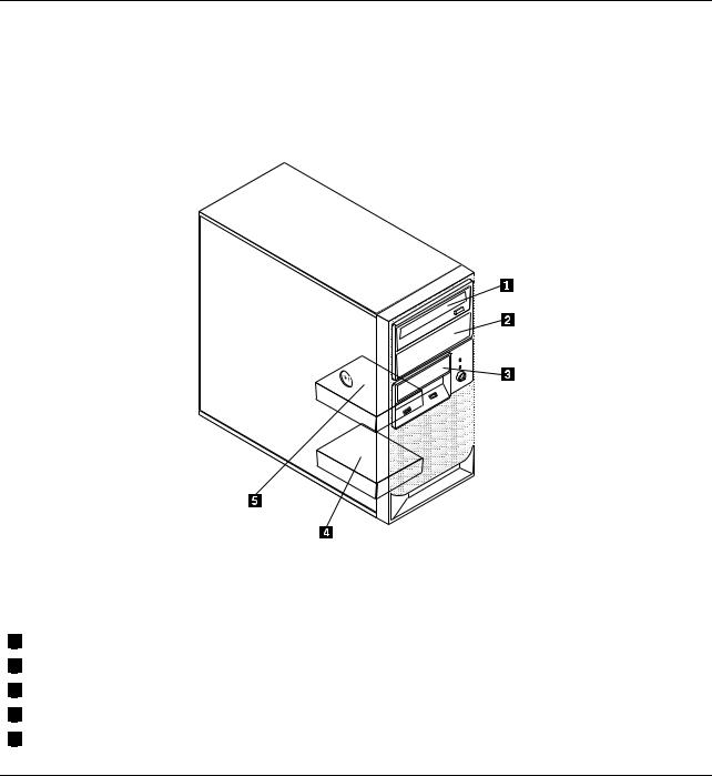
Front view
Figure 1 “Front control and connector locations” on page 9 shows the locations of the controls and connectors on the front of your server.
Figure 1. Front control and connector locations
1 |
Optical drive eject/close button |
2 |
Hard disk drive activity LED |
3 |
Power-on LED |
4 |
Power switch |
5 |
USB connectors (2) |
Rear view
Figure 2 “Rear connector locations” on page 10 shows the locations of the connectors on the rear of your server. Some connectors on the rear of your server are color-coded to help you determine where to connect the cables in your server.
© Copyright Lenovo 2011 |
9 |
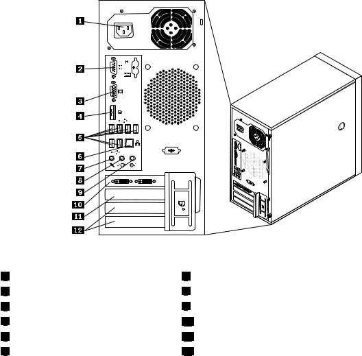
Figure 2. Rear connector locations
1 |
Power cord connector |
2 |
Serial port |
3 |
VGA monitor connector |
4 |
DisplayPort connector |
5 |
USB connectors (6) |
6 |
Ethernet connector |
7 Microphone connector
8 Audio line-out connector
9 Audio line-in connector
10 PCI Express x16 card slot
11 PCI Express x1 card slot
12 PCI card slots (2)
Connector |
Description |
Audio line-in connector |
Used to receive audio signals from an external audio device, such as a stereo |
|
system. When you attach an external audio device, a cable connects the audio |
|
line-out connector of the device to the audio line-in connector of the server. |
Audio line-out connector |
Used to send audio signals from the server to external devices, such as powered |
|
stereo speakers (speakers with built-in amplifiers), headphones, multimedia |
|
keyboards, or the audio line-in connector on a stereo system or other external |
|
recording device. |
DisplayPort connector |
Used to attach a high-performance monitor, a direct-drive monitor, or other devices |
|
that use a DisplayPort connector. |
Ethernet connector |
Used to attach an Ethernet cable for a local area network (LAN). |
|
Note: To operate the server within FCC Class B limits, use a Category 5 Ethernet |
|
cable. |
Microphone connector |
Used to attach a microphone to your server when you want to record sound or if |
|
you use speech-recognition software. |
Serial port |
Used to attach an external modem, a serial printer, or other devices that use a |
|
9-pin serial port. |
10 ThinkServer User Guide
Connector |
Description |
USB connector |
Used to attach a device that requires a USB connector, such as a USB keyboard, a |
|
USB mouse, a USB scanner, or a USB printer. If you have more than eight USB |
|
devices, you can purchase a USB hub, which you can use to connect additional |
|
USB devices. |
VGA monitor connector |
Used to attach a VGA monitor or other devices that use a VGA monitor connector. |
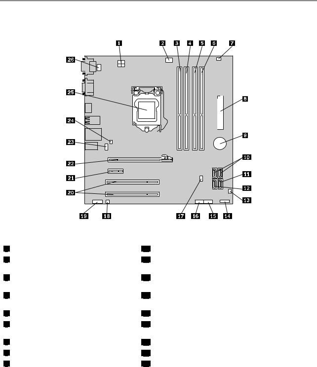
Locating parts on the system board
Figure 3 “System board part locations” on page 11 shows the locations of the parts on the system board.
Figure 3. System board part locations
1 |
4-pin power connector |
2 |
Microprocessor fan connector |
3 |
Memory slot 1 (DIMM1) |
4 |
Memory slot 2 (DIMM2) |
5 |
Memory slot 3 (DIMM3) |
6 |
Memory slot 4 (DIMM4) |
7 |
Thermal sensor connector |
8 |
24-pin power connector |
9 |
Battery |
14 |
Front panel connector for power switch and LED indicators |
15Front USB connector 1 (for connecting USB port 1 and 2 on the front bezel)
16Front USB connector 2 (for connecting additional USB devices)
17Clear CMOS (Complementary Metal Oxide Semiconductor) /Recovery jumper
18 |
Internal speaker connector |
19 Front audio connector (for connecting the microphone and headphone connectors on the front bezel)
20 |
PCI card slots (2) |
21 |
PCI Express x1 card slot |
22 |
PCI Express x16 graphics card slot |
Chapter 4. Locating parts, controls, and connectors 11
10 SATA connectors 1 and 2 (SATA 3.0 |
connectors) |
11 |
SATA connector 3 (SATA 2.0 connector) |
12 |
eSATA connector |
13 |
Front fan connector |
23 |
Rear fan connector |
24 |
Cover presence switch connector (Intrusion switch connector) |
25 |
Microprocessor |
26 |
PS/2 keyboard and mouse connector |
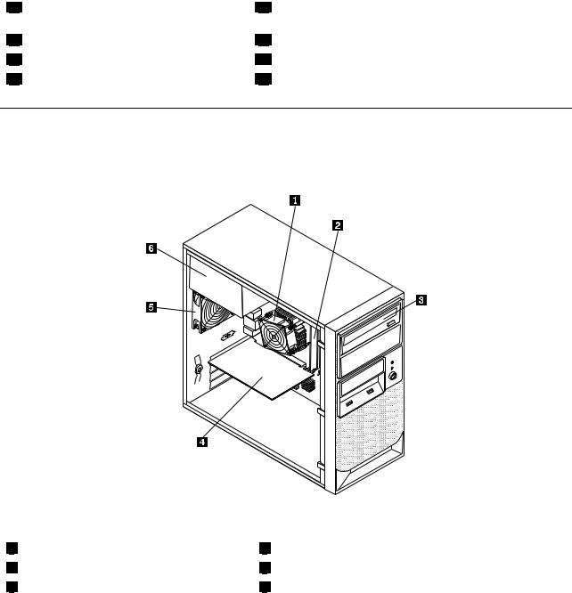
Internal components
Figure 4 “Component locations” on page 12 shows the locations of the various components in your server. To remove the server cover and access the inside of the server, see “Removing the server cover” on page 17.
Figure 4. Component locations
1 |
Heat sink and fan assembly |
2 |
Memory module |
3 |
Optical drive |
4 |
PCI card |
5 |
Rear fan assembly |
6 |
Power supply assembly |
12 ThinkServer User Guide
Internal drives
Internal drives are devices that your server uses to read and store data. You can add drives to your server to increase storage capacity and enable your server to read other types of media. Internal drives are installed in bays. In this manual, the bays are referred to as bay 1, bay 2, and so on.
Figure 5 “Drive bay locations” on page 13 shows the locations of the drive bays.
Figure 5. Drive bay locations
The following list describes the type and size of the drive that you can install in each bay:
1Bay 1 - Optical drive bay (with an optical drive installed on some models)
2Bay 2 - Optical drive bay
3Bay 3 - Card reader drive bay
4Bay 4 - Secondary SATA hard disk drive bay
5Bay 5 - Primary SATA hard disk drive bay (with a 3.5-inch SATA hard disk drive installed)
Machine type and model label
The machine type and model label identifies your computer. When you contact Lenovo for help, the machine type and model information helps support technicians to identify your computer and provide faster service.
Chapter 4. Locating parts, controls, and connectors 13
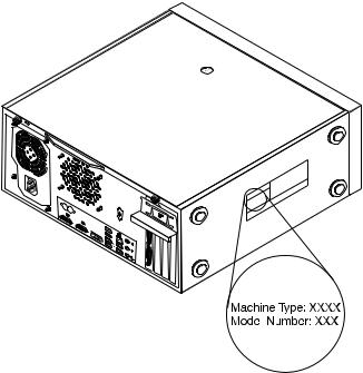
The following is a sample of the machine type and model label.
Figure 6. Machine type and model label
14 ThinkServer User Guide

Chapter 5. Installing, removing, or replacing hardware
This chapter provides instructions on how to install, remove, or replace hardware for your server.
This chapter contains the following topics:
•“Guidelines” on page 15
•“Removing the server cover” on page 17
•“Removing and reinstalling the front bezel” on page 18
•“Installing, removing, or replacing optional hardware devices” on page 20
•“Installing, removing, or replacing hardware devices” on page 34
•“Completing the parts replacement” on page 48
•“Installing security features” on page 51
Guidelines
This section provides some guidelines that you should read and understand before using your server.
Basic guidelines
Before you use the server, be sure to read and understand the following guidelines:
•Be sure to read and understand the Safety Information and the Warranty and Support Information at http://www.lenovo.com/support, and “Guidelines” on page 15. The information will help you work safely.
•When you install your new server, take the opportunity to download and apply the most recent firmware updates. This step will help to ensure that any known issues are addressed and that your server is ready to function at maximum levels of performance. To download firmware updates for your server, do the following:
1.Go to http://www.lenovo.com/support.
2.Click Download & Drivers ThinkServer and then follow the instructions on the Web page to download firmware updates for your server.
•Before you install optional hardware devices, make sure that the server is working correctly. If an
operating system is installed, turn on the server and make sure that the operating system starts. If no operating system is installed, make sure that a message BOOTMGR is missing is displayed, indicating that an operating system was not found but the server is working correctly. If the server is not working correctly, refer to Chapter 7 “Troubleshooting and diagnostics” on page 75 for detailed diagnostic information.
•Observe good housekeeping in the area where you are working. Put removed covers and other parts in a safe place.
•If you must turn on the server while the server cover is removed, make sure that no one is near the server and that no tools or other objects have been left inside the server.
•Do not attempt to lift an object that you think is too heavy for you. If you have to lift a heavy object, observe the following precautions:
–Make sure that you can stand safely without slipping.
–Distribute the weight of the object equally between your feet.
–Use a slow lifting force. Never move suddenly or twist when you lift a heavy object.
–To avoid straining the muscles in your back, lift by standing or by pushing up with your leg muscles.
© Copyright Lenovo 2011 |
15 |
•Make sure that you have an adequate number of properly grounded electrical outlets for the server, monitor, and other devices.
•Back up all important data before you make changes to drives.
•Have a small flat-blade screwdriver available.
•To view the error LEDs on the system board and internal components, leave the server connected to power.
•You do not have to turn off the server to install or replace hot-swap fans, redundant hot-swap ac power supplies, or hot-plug USB devices. However, you must turn off the server before performing any steps that involve installing, removing, or replacing adapter cables or non-hot-swap optional devices or components.
•After completing any installation, removal, or replacement procedure, reinstall all safety shields, guards, labels, and ground wires.
•For a list of supported optional devices for the server, go to http://www.lenovo.com/thinkserver.
•When working inside the server, you might find some tasks easier if you lay the server on its side. You might need to first pivot the foot stands inward and then lay the computer on its side.
System reliability guidelines
To help ensure proper cooling and system reliability, make sure that you follow these guidelines:
•Every drive bay has an internal drive installed or an Electro Magnetic Compatibility (EMC) shield installed.
•If the server has redundant power, every power supply bay has a power supply assembly installed.
•Leave adequate space around the server to make sure that the server cooling system works well.
•Properly route the cables. For some options, such as PCI cards, follow the cabling instructions that come with the options.
•Make sure that you replace a failing fan within 48 hours.
•When replacing a hot-swap drive, install the new hot-swap drive within two minutes of removal.
•Do not remove any air duct or air baffles while the server is running. Operating the server without the air duct or air baffles might cause the microprocessor to overheat.
•The second microprocessor socket always contains either a microprocessor socket cover or a microprocessor and heat sink assembly.
Handling static-sensitive devices
Attention:
Do not open the static-protective package containing the new part until the defective part has been removed from the server and you are ready to install the new part. Static electricity, although harmless to you, can seriously damage server components and parts.
When you handle server parts and components, take these precautions to avoid static-electricity damage:
•Limit your movement. Movement can cause static electricity to build up around you.
•Wear an electrostatic-discharge wrist strap, if one is available.
•Always carefully handle the parts and other components (such as PCI cards, memory modules, system boards, and microprocessors) by its edges or its frame. Do not touch solder joints, pins, or exposed circuitry.
•Prevent others from touching the parts and other computer components.
•Before you replace a new part, touch the static-protective package containing the new part to a metal expansion-slot cover or other unpainted metal surface on the server for at least two seconds. This reduces static electricity from the package and your body.
16 ThinkServer User Guide
•Remove the new part from the static-protective package and directly install it in the server without placing it on any other surface. If it is hard for you to do this in your specific situation, place the static-protective package of the new part on a smooth, level surface, and then place the new part on the static-protective package.
•Do not place the part on the server cover or other metal surface.
•Take additional care when handling devices during cold weather. Heating reduces indoor humidity and increases static electricity.
Removing the server cover
Attention:
Do not open your server or attempt any repair before reading and understanding the Safety Information and the
Warranty and Support Information on the ThinkServer Documentation DVD that came with your product, and “Guidelines” on page 15. To obtain a copy of the publications, go to:
http://www.lenovo.com/support
This section provides instructions on how to remove the server cover.
CAUTION:
Turn off the server and wait three to five minutes to let the server cool before removing the server cover.
To remove the server cover, do the following:
1.Remove any media from the drives and turn off all attached devices and the server.
2.Disconnect all power cords from electrical outlets.
3.Disconnect the power cords, Input/Output (I/O) cables, and any other cables that are connected to the server. See “Front view” on page 9 and “Rear view” on page 9.
4.Remove any locking device that secures the server cover, such as a padlock or an integrated cable lock. See “Integrated cable lock” on page 51and “Padlock” on page 51.
5.Remove the two thumbscrews that secure the server cover.
Chapter 5. Installing, removing, or replacing hardware 17
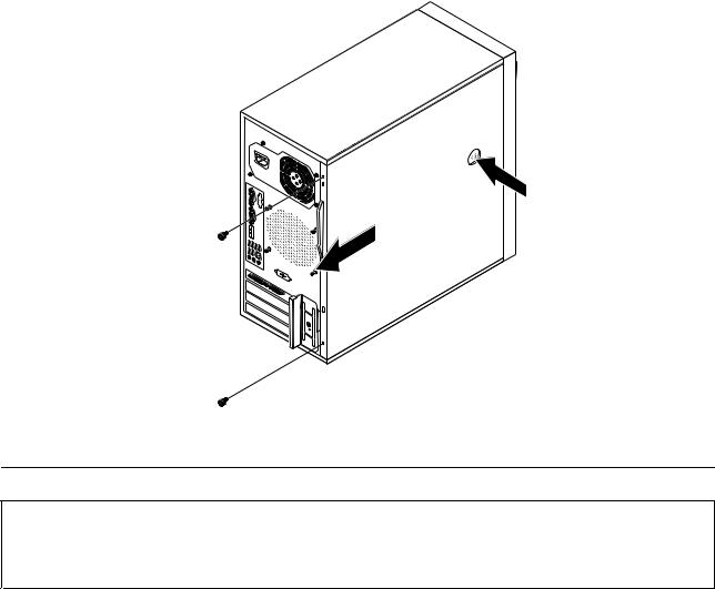
6.Press the cover-release button on the side of the server and slide the cover to the rear of the server to remove the cover.
Figure 7. Removing the server cover
Removing and reinstalling the front bezel
Attention:
Do not open your server or attempt any repair before reading and understanding the Safety Information and the
Warranty and Support Information on the ThinkServer Documentation DVD that came with your product, and “Guidelines” on page 15. To obtain a copy of the publications, go to:
http://www.lenovo.com/support
This section provides instructions on how to remove and reinstall the front bezel.
To remove and reinstall the front bezel, do the following:
1.Remove all media from the drives and turn off all attached devices and the server. Then, disconnect all power cords from electrical outlets and disconnect all cables that are connected to the server.
2.Remove the server cover. See “Removing the server cover” on page 17.
18 ThinkServer User Guide
Loading...