


P/N 875034M Rev. C 07/2010
This manual is one of a set of two supporting this product. Refer to P/N 850040M for Installation Instructions.
This manual is available in French. Order P/N 506223-26.
Ce manuel est disponible en francais. Simplement en faire la demande numéro de la pièce 506223-26.
WH Report No. 3106807
CARE AND OPERATION INSTRUCTIONS
B-Vent Gas Fireplaces
42" LMBV Models
MODELS
Millivolt Models |
Electronic Models |
lmbv-42rmn |
lmbv-42ren |
lmbv-42rmp |
|
|
|
WARNING |
AVERTISSEMENT |
HOT GLASS WILL |
UNE SURFACE VITRÉE CHAUDE PEUT |
CAUSE BURNS. |
CAUSER DES BRÛLURES. |
DO NOT TOUCH GLASS |
LAISSER REFROIDIR LA SURFACE |
UNTIL COOLED. |
VITRÉE AVANT D'Y TOUCHER. |
NEVER ALLOW CHILDREN TO |
NE PERMETTEZ JAMAIS À UN ENFANT |
TOUCH GLASS. |
DE TOUCHER LA SURFACE VITRÉE. |
This appliance may be installed in an aftermarket permanently located, manufactured home (USA only) or mobile home, where not prohibited by local codes. This appliance is only for use with the type of gas indicated on the rating
WARNING: If the information in these instructions is
causing property damage, personal injury or death.
-
and liquids in the vicinity of this or any other appliance.
-WHAT TO DO IF YOU SMELL GAS
•Do not try to light any appliance.
•Do not touch any electrical switch; do not use any phone in your building.
•Immediately call your gas supplier from a neighbor’s phone. Follow the gas supplier’s instructions.
•
department.
-
installer, service agency or the gas supplier.
INSTALLER: Leave this manual with the appliance. CONSUMER: Retain this manual for future reference.
INSTALLATEUR: Laissez cette notice avec l'appareil. CONSOMMATEUR: Conservez cette notice pour consultation ultérieure.
AVERTISSEMENT: Assurez-vous de bien suivre les instructions données dans cette notice pour réduire au minimum le risque d’incindie ou d’explosion ou pour éviter tout dommage matériel, toute blessure ou la mort.
-Ne pas entreposer ni utilizer d’essence ni d’autres de cet appareil ou de tout autre appareil.
-QUE FAIRE SI VOUS SENTEZ UNE ODEUR DE GAZ:
•Ne pas tenter d’allumer d’appareil.
•Ne touchez à aucan interrupteur. Ne pas vous servir des téléphones se trouvant dans le bâtiment où vous trouvez.
•Appelez immédiatement votre fournisseur de gaz depuis un voisin. Suivez les instructions du fournisseur.
•Si vous ne pouvez rejoindre le fournisseur de gaz, appelez le service des incindies.
-L’installation et l’entretien doivent être assurés par un le fournisseur de gaz.
LENNOX MERIT® SERIES B-VENT GAS FIREPLACES • 42" LMBV MODELS • CARE AND OPERATION INSTRUCTIONS
Congratulations!
In selecting this LENNOX B-vented gas appliance, you have chosen one of the finest and most dependable fireplaces available. This gas fireplaces is a beautiful, prestigious alternative to a wood burning fireplace. Welcome to a family of tens of thousands of satisfied LENNOX fireplace owners.
Please read and carefully follow all of the instructions found in this manual. Please pay special attention to the safety instructions provided in this manual. The Care and Operation Instructions included herein will help to ensure many years of dependable and enjoyable service from your LENNOX product.
TABLE OF CONTENTS |
|
|
Introduction....................................... |
page |
2 |
General Information........................... |
page |
2 |
Operation/Care of Your Appliance...... |
page |
3 |
Damper & Outside Air Controls......... |
page |
4 |
Manual Limit Switch.......................... |
page |
5 |
Attaching "Safety-in-Operation" |
|
|
Warnings............................. |
page |
6 |
Maintenance...................................... |
page |
7 |
Millivolt Appliance Checkout.............. |
page |
7 |
Electronic Appliance Checkout........... |
page |
7 |
Maintenance Schedule....................... |
page |
8 |
Log and Rockwool Placement........... |
page |
9 |
Wiring Diagrams................................ |
page |
10 |
Lighting Instructions – Millivolt......... |
page |
11 |
Lighting Instructions – Electronic...... |
page |
13 |
Troubleshooting Guide – Millivolt...... |
page |
15 |
Troubleshooting Guide – Electronic... |
page |
16 |
Warranty............................................ |
page |
17 |
Product Reference Information.......... |
page |
17 |
Replacement Parts............................. |
page |
17 |
Accessory Components..................... |
page |
18 |
Replacement Parts List...................... |
page |
19 |
Introduction
The millivolt appliances are designed to operate on either natural or propane gas. A millivolt gas control valve with piezo ignition system provides safe, efficient operation.
The electronic appliances are designed to operate on either natural or propane gas. An electronic intermittent ignition system provides safe, efficient operation. External electrical power is required to operate these units.
These appliances comply with National Safety Standards and are tested and listed by Warnock Hersey (Report No. 3106807) to ANSI Z21.50, latest edition (in Canada, CSA 2.22, latest edition), andCAN/CGA-2.17-M91inbothUSAand
Canada, as vented gas fireplaces.
Installation must conform to local codes. In the absence of local codes, installation must comply with the current National Fuel Gas Code,
ANSIZ223.1(NFPA54).(InCanada,thecurrent CAN/CGA B149 installation code.) Electrical wiring must comply with local codes. In the absence of local codes, installation must be in accordance with the National Electrical Code, NFPA70 - (latestedition). (InCanada, thecurrent
CSA C22.1 Canadian Electric Code.)
Do not attempt to alter or modify the construction of the appliance or its components. Any modification or alteration may void the warranty, certification and Listings of this unit.
Warning: Improper installation, adjustment, alteration, service or maintenance can cause injury or property damage. Refer to this manual. For assistance or additional information consult a qualified installer, service agency or the gas supplier.
Warning: Electronic models of these appliances are equipped with a three-prong (grounding) plug utilized in connecting the electronic components to the junction box in the lower compartment. This grounding plug provides protection against shock hazard and should be plugged directly into the prop- erlygroundedthree-prongrecep- tacle. DO NOT cut or remove the grounding prong from the plug.
General Information
Note: Installation and repair should be performed by a qualified service person. The appliance should be inspected annually by a qualified professional service technician. More frequent inspections and cleanings may be required due to excessive lint from carpeting, bedding material, etc. It is imperative that the controlcompartment,burnersandcirculatingair passage ways of the appliance be kept clean.
S'assurer que le brùleur et le compartiment des commandes sont propres. Voir les instructions d'installation et d'utilisation qui accompagnent l'apareil.
Provide adequate clearances around air openings and adequate accessibility clearance for service and proper operation. Never obstruct the front openings of the appliance.
Due to high temperatures the appliance should be located out of traffic and away from furniture and draperies. Locate furniture and window coverings accordingly.
Warning: THEse FIREPLACES ARE VENTED DECORATIVE GAS APPLIANCES. DO NOT BURN WOOD OR OTHER MATERIAL IN THESE APPLIANCES.
These appliances are designed to operate on natural or propane gas only. The use of other fuels or combination of fuels will degrade the performance of this system and may be dangerous.
Input of appliance is 30,000 BTU/HR.
Gas |
Orifice |
|
|
Type |
Size |
Elevation |
|
Natural |
#37 |
0 - 4500' |
|
(0.104) |
(0 - 1370 m) |
||
|
|
|
|
Propane |
(0.065) |
0 - 4500' |
|
(0 - 1370 m) |
|||
|
|
||
|
|
|
Nominal operating pressures for the manifold side of the gas control system are; 3.5 inches water column (0.87 kPa) for natural gas models and 10 inches water column (2.49 kPa) for propane gas models.
2
NOTE: DIAGRAMS & ILLUSTRATIONS ARE NOT TO SCALE.
LENNOX MERIT® SERIES B-VENT GAS FIREPLACES • 42" LMBV MODELS • CARE AND OPERATION INSTRUCTIONS
Do not use these appliances if any part has been under water. Immediately call a qualified, professional service technician to inspect the appliance and to replace any parts of the control system and any gas control which have been under water.
Ne pas se servir de cet appareil s'il a été plongédansl'eau,complètementouenpartie. Appeler un technicien qualifié pour inspecter l'appareiletremplacertoutepartiedusystème de contrôle et toute commande qui ont été plongés dans l'leau.
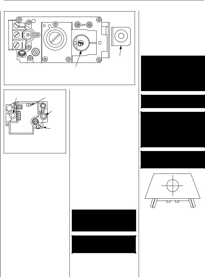
Test gage connections are provided on the front of the millivolt gas control valve (identified E for the inlet and A for the manifold side. (See
Figure 2 ). A 1/8" NPT test gage connection is provided at the inlet and manifold side of the electronic gas control valve (See Figure 3 ).
Minimum inlet gas pressure to the appliance is
4.5 inches water column (1.24 kPa) for natural gas and 11 inches water column (2.74 kPa) for propane for the purpose of input adjustment.
Maximum inlet gas supply pressure to the appliance is 10.5 inches water column (2.62 kPa) for natural gas and 13.0 inches water column
(3.23 kPa) for propane.
The appliance must be isolated from the gas supply piping system (by closing its individual manual shut-off valve) during any pressure testing of the gas supply piping system at test pressures equal to or less than 1/2 psig (3.5 kPa).
The appliance and its individual shut-off valve must be disconnected from the gas supply piping system during any pressure testing of that system at pressures in excess of 1/2 psig (3.5 kPa).
These appliances must not be connected to a chimney or flue serving a separate solid fuel burning appliance.
Warning: Failure to comply with the installation and operating instructions provided in this document will result in an improperlyinstalledandoperating appliance, voiding its warranty. Any change to this appliance and/or its operating controls is dangerous. Improper installation or use of this appliance cancause serious injuryordeath form fire, burns, explosion or carbon monoxide poisoning.
Carbon Monoxide Poisoning: Early signs of carbon monoxide poisoning are similar to the flu with headaches, dizziness and/or nausea. If you have these signs, obtain fresh air immediately. Turn off the gas supply to the appliance and have it serviced by a qualified professional, as it may not be operating correctly.
Warning: B-Vent appliances are not designed to operate in negatively pressured environments (pressure within the home is less than pressures outside). Significant negatively pressured environmentscausedbyweather, home design, or other devices may impact the operation of these appliances. Negative pressures may result in poor flame appearance, sooting, damage to propertyand/orseverepersonal injury. Do not operate these appliances in negatively pressured environments.
Warning: children and adults should be alerted to the hazards of high surface temperatures. Use caution around the appliance to avoid burns or clothing ignition. Young children should be carefully supervised when they are in the same room as the appliance.
Warning: Do not place clothing or other flammable materials on or near this appliance.
AvertisSement: SURVEILLER LES ENFANTS. GARDER LES VêTEMENTS, LES MEUBLES, L'ESSENCE OU AUTRES LIQUIDES à VAPEUR INFLAMMABLES LoIN DE L'APPAREIL.
Operation and care of your appliance
1. Appliance operation may be controlled through a remotely located optional wall switch. Separate switches may provide independent control for the remote controlled fireplace operation (optional equipment).
In lieu of remote or remote wall switch operation, the appliance must be operated directly through the controls located on the front of the valve located within the control compartment under the removable refractory access panel,
Figure 1.
Gas Controls on Valve
Piezo
 Ignitor
Access Panel
SIT Valve Shown
Figure 1
Operation of millivolt and electronic gas control systems are different. Before lighting and operating your appliance determine if you have a millivolt or electronic appliance. Refer to Figure 1 to access the gas control compartment below the lower refractory panel. Millivolt appliances will be fitted with one of the two gas control valves shown in Figure 2. Appliances with electronic systems will be fitted with the electronic valve shown in Figure 3. Familiarize yourself with the differing controls for the valve your appliance uses.
To light millivolt appliances refer to the detailed lighting instructions found in both English and French on pages 10 and 11 of these instructions respectively. Millivolt and electronic appliance lighting instructions may also be found on the pull out labels attached to the gas control valve located within the gas control compartment. Refer to Figure 2 to locate the appropriate location for the spark ignitor used with your appliance.
If your appliance is equipped with an optional remote wall switch or remote control kit the appliance main burner may be turned on and off with the wall switch or remote control. If the appliance is not equipped with a wall or remote control, the main burner must be turned off and on with the gas control knob. Turn the knob counter-clockwise from the PILOT position to ON to light the main burner, and clockwise from ON to PILOT to turn off the main burner.
3
NOTE: DIAGRAMS & ILLUSTRATIONS ARE NOT TO SCALE.
LENNOX MERIT® SERIES B-VENT GAS FIREPLACES • 42" LMBV MODELS • CARE AND OPERATION INSTRUCTIONS
|
|
|
A |
E |
TPTH |
|
|
|
|
TP |
|
|
F |
|
|
|
|
F |
|
|
|
|
O |
|
|
|
|
|
P |
|
|
|
|
I |
|
|
|
|
L |
TH |
|
|
|
O |
|
|
|
T |
|
|
|
|
|
|
|
|
|
NO |
|
|
|
P |
|
|
|
I |
|
Piezo |
|
L |
|
|
||
TO |
|
|
|
|
|
|
|
|
Ignitor |
SIT Millivolt Valve |
|
|
Gas Control |
|
|
|
|
Knob |
|
Figure 2 |
|
|
|
|
Manifold Presssure Port |
ON/OFF Switch |
||
CONTROL |
OFF ON |
|
Inlet |
|
|
I |
Pressure |
ITEIGN |
|
|
Port |
|
|
|
|
|
|
SIP |
|
|
|
|
Electronic |
|
|
|
Gas Control |
|
|
|
Valve |
|
Honeywell Electronic |
Figure 3 |
Gas Valve |
To light electronic appliances refer to the detailed lighting instructions found in both English and French on pages 12 and 13 of these instructions respectively. Millivolt and electronic appliance lighting instructions may also be found on the pull out labels attached to the gas control valve located within the gas control compartment.
If your appliance is equipped with an optional remote wall switch or remote control kit the appliance main burner may be turner on and off with the wall switch or remote control. If the appliance is not equipped with a wall switch or remote control, the main burner must be turned off and on with the gas control switch. Toggle the switch from ON to OFF to operate the main burner from ON to OFF.
2. When lit for the first time, this appliance will emit a slight odor for an hour or two. This is due to the “burn-in” of internal paints and lubricants used in the manufacturing process.
3.Keep lower control compartment clean by vacuuming or brushing at least twice a year. More frequent cleaning may be required due to excessivelintfromcarpeting,beddingmaterials, etc. It is important that control compartments, burners and circulating air passageways of the appliance be kept clean and clear of obstruction of ventilating and combustion air.
4.Always turn off gas to the pilot (millivolt appliances) before cleaning. Before re-lighting, refer to the lighting instructions in this manual. Instructions are also found on a pull-out panel located on the floor of the appliance.
5.Always keep the appliance area clear and free from combustible materials, gasoline and other flammable liquids.
6.Remember, Millivolt appliances have a continuous burning pilot flame. Exercise caution when using products with combustible vapors.
7.Clean the optional glass doors only when necessary. Wipe surface with clean, dampened, soft cloth. Follow with dry, soft towel as desired. Take care not to scratch the glass surface.
Warning: Replace any safety screen or guard removed for servicing an appliance prior to operating the appliance.
Warning: Do not use abrasive cleaners. Never clean the glass when it is hot.
Caution: Do not attempt to touch the doors with your hands while the fireplace is in use. Always use door handles. Doors will become very hot when fireplace is in use.
Caution: Never operate this appliance with a broken or damaged glass door. Remove or replace any broken glass door before operating.
Warning: Do not attempt to repair broken glass components. Replace any broken doors only withcompletedoorkits,obtained from Lennox. Remove any broken glass pieces by vacuuming them out completely.
Warning: Do not strike or slam shut optional glass doors.
Warning: Fireplaces equipped with optional accessory doors should be operated only with the doors fully open or fully closed (Figure 4 ). Thisappliancemayonly be fitted with doors certified for use with the appliance.
AvertisSement: Pour utilisation uniquement avec les portes en verre certifiêes avec l'appareil.
Fully Open or
Fully Closed
Figure 4
Damper and Combustion Air Controls
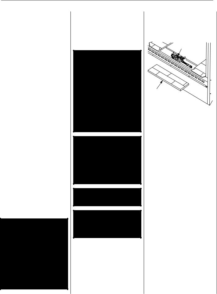
Thisapplianceisfittedwithamanuallycontrolled vent damper. The vent damper should be closed when the appliance is not in use to prevent cold air from entering the home through the venting system. The damper is controlled through the use of a control lever located within the appliance opening at the top center in front of the firebox lintel (see Figure 5 ).
4
NOTE: DIAGRAMS & ILLUSTRATIONS ARE NOT TO SCALE.
LENNOX MERIT® SERIES B-VENT GAS FIREPLACES • 42" LMBV MODELS • CARE AND OPERATION INSTRUCTIONS
The control lever snaps into place at either extreme of its range of motion. When locked in position all the way to the right, the damper is open. When locked in position all the way to the left, the damper is closed.
The damper lever actuates a switch, (see wiring diagram) which will prevent the appliance main burner from lighting unless the damper is locked open. The appliance flue damper must always remain open when operating.
Warning: Damper must be in open position when appliance main burner is operating.
Avertissement: Le registre doit être en position ouverte lorsque le ou les bruleurs principaux de l'appereil fonctionnment.
Back Wall of Chase/Enclosure |
Optional FOAK |
|
Including Finishing Materials |
||
Combustion Air Kit |
||
if any |
||
|
||
C |
|
|
|
G |
H  A
A 
 H
H
Rough Framing Face (Unfinished Shown)
Inside Chase
Figure 5
Many appliances are equipped when installed with an outside (make-up) air vent system that is designed to provide the appliance with outside make-up air for combustion when in operation. The actuator for the outside air system is standard on all appliances but must not be operated if the complete system is not installed. Refer to Figure 6. When the complete outside air vent system is installed, the installer will remove the actuator locking screw.
If your screw is not removed and you have reason to believe that you have a complete outside air system, contact your distributor to have your appliance inspected for the presence of the complete system.
DO NOT assume that you have this system in place because you have an actuating lever present on your appliance front face.
|
|
|
|
|
|
|
|
Pulltheactuatorforwardtoopenthecombustion |
|
|
Warning: Do not operate the |
|
|||||||
|
|
airdoor,andpushitbacktoclose. To"lock"the |
|||||||
|
combustion air actuator unless |
|
|||||||
|
|
combustion air door closed, ensure the actuator |
|||||||
|
a complete outside air vent sys- |
|
|||||||
|
|
is pushed all the way back, then push the end |
|||||||
|
tem has been installed with your |
|
of the actuators to the right until the step in the |
||||||
|
appliance. |
|
actuator moves behind the appliance front face |
||||||
|
|
|
|
|
|
|
|
within the slotted opening. |
|
|
|
|
Combustion Air |
||||||
|
|
|
Manually-reset blocked flue safety |
||||||
|
|
|
Actuator |
||||||
|
|
|
|
|
|
|
|
switch |
|
|
|
|
|
|
|
|
|
This appliance is equipped with a manually-reset |
|
|
|
|
|
|
|
|
|
||
|
|
|
|
|
|
|
|
blocked flue safety switch. Refer to Figure 7 |
|
|
|
|
|
|
|
|
|
||
|
|
|
|
|
|
|
|
for its location. If during appliance operation, |
|
|
|
|
|
|
|
|
|
the flame goes out (independently of the burner |
|
|
|
|
|
|
|
|
|
||
|
Remove Locking Screw |
on/off wall switch), it may be due to the opera- |
|||||||
|
tion of this safety limit switch. First allow the |
||||||||
|
and “Pop” Actuator to the |
||||||||
|
Left Before Initial Use |
appliance to cool, then reset the safety switch |
|||||||
|
|
|
|
|
|
|
|
by pushing the red reset button on the back |
|
|
|
|
|
|
|
|
|
||
|
|
|
|
|
|
|
|
of the switch. |
|
|
|
|
|
|
|
|
|
Caution: The Electronic appliance |
|
|
|
|
|
|
|
|
|
||
|
|
|
|
|
|
|
|
should be turned off before removing |
|
|
|
|
|
|
|
|
|
||
|
|
|
|
|
|
|
|
||
|
|
|
|
|
|
|
|
the limit switch. |
|
|
|
|
|
|
|
|
|
To access the safety limit switch reset button, |
|
|
|
|
|
|
|
|
|
||
|
Pull Forward to Open, |
||||||||
|
remove the screen rod and screen from the |
||||||||
|
Push Back to Close |
right side of the fireplace. Unscrew two screws |
|||||||
|
|
|
|
|
|
|
|
||
|
Figure 6 |
and remove the limit switch with low voltage |
|||||||
|
wires attached. Push the reset button, then |
||||||||
|
|
|
|
|
|
|
|
||
|
To provide outside combustion air to your |
reinstall the limit switch. Reinstall the screen |
|||||||
|
and rod. At this time turn the electronic appli- |
||||||||
|
appliance while it is in operation, locate the |
||||||||
|
ance back on. |
||||||||
|
combustion air actuator along the right side |
||||||||
|
|
|
|||||||
|
of the appliance opening (Figure 5 ). |
The appliance should then relight and remain |
|||||||
|
|
|
|
|
|
|
|
||
|
To operate, push the end of the actuator to the |
lit. If this does not occur, turn off the appliance |
|||||||
|
left as shown in Figure 6, until it "pops" free of |
and call a qualified service technician. |
|||||||
|
its "locked" position. |
|
|
||||||
|
|
|
|
|
|
|
|
|
|
|
|
|
|
|
|
|
|
Limit Switch Screws |
|
Screen
 Rod
Rod
Manual |
Screen |
Reset |
|
Limit |
|
Switch |
|
Figure 7 |
Lintel Extension |
Right Side Refractory Panel |
|
|
5
NOTE: DIAGRAMS & ILLUSTRATIONS ARE NOT TO SCALE.
LENNOX MERIT® SERIES B-VENT GAS FIREPLACES • 42" LMBV MODELS • CARE AND OPERATION INSTRUCTIONS
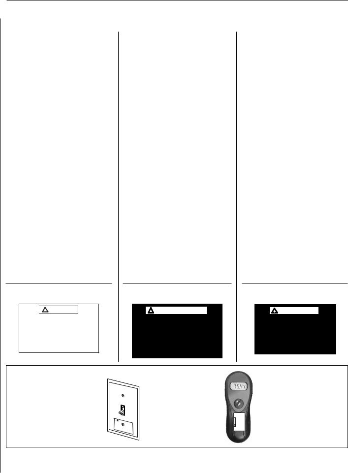
HOMEOWNER’S INSTRUCTIONS - ATTACHING "SAFETY-IN-OPERATION" WARNINGS
Attaching Safety in Operation Warnings
Yourfireplacehas beenfurnishedwithsafetyinstruction labels that are to be affixed to the operation and control point of the fireplace. A safety instruction label should be affixed to the wall switch plate where the fireplace is turned on and off (See Figure A) and if used on the remote control handheld transmitter (Figure B). The warnings should already have been put in place when the fireplace initial set-up was completed. If they are not affixed at these spots, locate the multi-lingual adhesive labels provided with these instructions and proceed as follows:
1.Locate the wall switch that controls the fireplace (verify the switch operates the fireplace by turning it on and off). Clean the wall switch plate thoroughly to remove any dust and oils. Affix the label to the surface of the plate of the wall switch that controls the fireplace (Figure A). Choose the language primarily spoken in the home.
2.Ifaremotecontrolisusedtocontrolthefireplace, locate the transmitter and clean it thoroughly to remove any dust and oils. Affix the label to the surface of handheld transmitter (Figure B). Choose the language primarily spoken in the home.
3.If you are unable to locate the labels, please call Lennox Hearth Products or your nearest Lennox Hearth Products dealer to receive additional safety instruction labels free of charge.
Cat. No. H8024 Replacement Label Kit
LENNOX HEARTH PRODUCTS 1-800-9-LENNOX
Note: English is red text on clear label. French and Spanish are white text on black label.
SAFETY LABEL DIAGRAMS

 WARNING
Hot Fireplace Will Cause Severe Burns
Never Allow Children to Touch Glass or other Fireplace Parts
Apposition des mises en garde relatives à la sécurité d’utilisation
Votrefoyeraétélivréavecdesétiquettesdesécuritéqui doivent être collées à côté des dispositifs de contrôle du foyer. Une étiquette de sécurité devrait être collée sur la plaque de l’interrupteur contrôlant l’allumage du foyer (voir Figure A) et, le cas échéant, sur le boîtier de la télécommande (Figure B). Les mises en garde auraient dû être collées au moment de l’installation initiale du foyer. Si ce n’est pas le cas, prenez les
étiquettes adhésives multilingues fournies avec ces instructions et procédez comme suit:
1.Repérezl’interrupteurquicontrôlelefoyer(vérifiez que l’interrupteur contrôle le fonctionnement du foyer en le faisant basculer de Marche à Arrêt, et vice-versa). Nettoyez soigneusement la plaque murale de l’interrupteur pour éliminer la poussière et les traces de graisse ou d’huile. Collez l’étiquette sur la surface de la plaque de l’interrupteur mural quicontrôlelefoyer(FigureA). Choisissezlalangue qui est principalement parlée dans la résidence du propriétaire.
2.Si une télécommande est utilisée pour contrôler le foyer, nettoyez la soigneusement pour éliminer la poussière et les traces de graisse ou d’huile. Collez l’étiquette sur le boîtier de la télécommande
(Figure B). Choisissez la langue qui est principale ment parlée dans la résidence du propriétaire.
3.Si vous ne trouvez pas les étiquettes, veuillez appeler Lennox Hearth Products ou votre distribu teur Lennox Hearth Products local pour recevoir gratuitement des étiquettes supplémentaires.
Étiquettes de remplacement, n° cat. H8024
LENNOX HEARTH PRODUCTS 1-800-9-LENNOX
Remarque : Le texte anglais est rouge sur un support transparent. Le texte français et espagnol est blanc sur un support noir.
DIAGRAMMES DES ÉTIQUETTES DE SÉCURITÉ

 AVERTISSEMENT
Un foyer chaud peut causer de graves brûlures
Ne laissez jamais un enfant toucher à la vitre ou à toutes autres parties du foyer
Colocacióndeadvertenciasdeseguridad
en operación
Su chimenea incluye etiquetas de instrucciones de seguridadquedebencolocarseenelpuntodeoperación y control de la chimenea. Se debe colocar una etiqueta deinstruccionesdeseguridadenlaplacadelinterruptor de pared desde el cual se enciende y se apaga la chimenea (ver la FiguraA) y en el transmisor de control remoto (Figura B) si se usa. Las advertencias ya deben haberse colocado cuando se completó la instalación inicial de la chimenea. Si no están colocadas en estos lugares,encuentrelasetiquetasadhesivasmultilingües proporcionadas con estas instrucciones y prosiga de la siguiente manera:
1.Identifique el interruptor de pared que controla la chimenea (verifique que el interruptor opera la chimenea encendiéndola y apagándola). Limpie bien la placa del interruptor de pared para quitar el polvo y aceite. Pegue la etiqueta en la superficie de la placa del interruptor que controla la chimenea (Figura A). Seleccione el idioma que más se habla en la casa.
2.Si se usa un control remoto para controlar la chimenea, encuentre el transmisor y límpielo bien para quitar el polvo y aceite. Pegue la etiqueta en la superficie del transmisor (Figura B). Seleccione el idioma que más se habla en la casa.
3.Sinopuedeencontrarlas etiquetas, sírvasellamara Lennox Hearth Products o al distribuidor de Lennox Hearth Products más cercano para recibir etiquetas deinstruccionesdeseguridadadicionalesgratuitas.
Juego de etiquetas de repuesto - Nº de cat. H8024
LENNOX HEARTH PRODUCTS 1-800-9-LENNOX
Nota: La etiqueta en inglés es transparente con texto rojo. Las etiquetas en francés y español son negras con texto blanco.
DIAGRAMAS DE ETIQUETAS DE SEGURIDAD
 ADVERTENCIA
La chimenea caliente causará quemaduras graves
Nunca permita que los niños toquen el vidrio ni otras partes de la chimenea
Figure A
Un |
|
A |
R |
|
|
|
|
|
VE |
|
|
||
de foyer chaudTISSEMENT |
||||||
Ne |
graves |
|
peut |
|||
laissez |
brûlures causer |
|||||
|
jamais |
|
||||
toucher |
|
un |
||||
autres |
|
à la |
|
|||
|
|
|
vitre ou àenfant |
|||
|
|
parties du |
|
|||
|
|
|
|
|
foyertoutes |
|
Figure B
WARNING Hot Fireplace Will Cause Severe Burns |
Never Allow Children to Touch Glass or other Fireplace Parts |
6
NOTE: DIAGRAMS & ILLUSTRATIONS ARE NOT TO SCALE.
 Loading...