


G61MP
Service Literature
Corp. 0308−L6
Revised 10−2004
G61MP SERIES UNITS
G61MP series units are high−efficiency multi−position (upflow, downflow, horizontal right and left) gas furnaces manufactured with Lennox Duralok Plust heat exchangers formed of aluminized steel. G61MP units are available in heating capacities of 44,000 to 132,000 Btuh (13.0.0 to 38.6 kW) and cooling applications from 2 to 5 tons (7.0 kW to 17.5 kW)) up to 5 tons. Refer to Engineering Handbook for proper sizing.
Units are factory equipped for use with natural gas. Kits are available for conversion to LPG operation. G61MP model units are equipped with the Two−Stage Integrated SureLight control. All G61MP units meet the California Nitrogen Oxides (NOx) Standards and California Seasonal Efficiency requirements. All units use a redundant gas valve to assure safety shut−off as required by C.S.A.
All specifications in this manual are subject to change. Procedures outlined in this manual are presented as a recommendation only and do not supersede or replace local or state codes. In the absence of local or state codes, the guidelines and procedures outlined in this manual (except where noted) are recommendations only and do not constitute code.
TABLE OF CONTENTS
Introduction . . . . . . . . . . . . . . . . . . . . . . . . . . . . . . . . . . . . 1
Specifications . . . . . . . . . . . . . . . . . . . . . . . . . . . . . . . . . . 2
Blower Data . . . . . . . . . . . . . . . . . . . . . . . . . . . . . . . . . . . 4
Parts Identification . . . . . . . . . . . . . . . . . . . . . . . . . . . . . . 7
I Unit Components . . . . . . . . . . . . . . . . . . . . . . . . . . . . . . 8
II Installation . . . . . . . . . . . . . . . . . . . . . . . . . . . . . . . . . 16
III Start Up . . . . . . . . . . . . . . . . . . . . . . . . . . . . . . . . . . . . 30
IV Heating System Service Checks . . . . . . . . . . . . . . 31
V Typical Operating Characteristics . . . . . . . . . . . . . . 34
VI Maintenance . . . . . . . . . . . . . . . . . . . . . . . . . . . . . . . 35
VII Wiring and Sequence of Operation . . . . . . . . . . . . 38
VIII Field Wiring and Jumper Setting . . . . . . . . . . . . . 46
IX Control Board Troubleshooting . . . . . . . . . . . . . . . . 48
 IMPORTANT
Improper installation, adjustment, alteration, service or maintenance can cause property damage, personal injury or loss of life. Installation and service must be performed by a qualified installer, service agency or the gas supplier.
 WARNING
Electric shock hazard. Can cause injury or death. Before attempting to perform any service or maintenance, turn the electrical power to unit OFF at disconnect switch(es). Unit may have multiple power supplies.
WARNING
Sharp edges.
Be careful when servicing unit to avoid sharp edges which may result in personal injury.
Page 1
♥ 2003 Lennox Industries Inc.

SPECIFICATIONS
Gas |
|
Model No. |
G61MP−36B−045 |
G61MP−36B−070 |
G61MP−48C−090 |
G61MP−60C−090 |
|
Heating |
High |
Input − Btuh (kW) |
44,000 (12.9) |
66,000 (19.3) |
88,000 (25.8) |
88,000 (25.8) |
|
Performance |
|||||||
Fire |
Output − Btuh (kW) |
41,000 (12.0) |
62,000 (18.2) |
83,000 (24.3) |
84,000 (24.6) |
||
|
|||||||
|
|
||||||
|
Temperature rise range − _F (_C) |
25 − 55 (14 − 31) |
35 − 65 (21 − 39) |
35 − 65 (21 − 39) |
25 − 55 (14 − 31) |
||
|
|
|
|
|
|
|
|
|
Low |
Input − Btuh (kW) |
30,000 (8.8) |
45,000 (13.2) |
60,000 (17.6) |
60,000 (17.6) |
|
|
Fire |
Output − Btuh (kW) |
28,000 (8.2) |
43,000 (12.6) |
57,000 (16.7) |
58,000 (17.0) |
|
|
|
||||||
|
Temperature rise range − _F (_C) |
10 − 40 (6 − 24) |
20 − 50 (12 − 30) |
25 − 55 (14 − 31) |
15 − 45 (9 − 27) |
||
|
|
|
|
|
|
|
|
|
|
1 AFUE |
94.1% |
94.1% |
94.1% |
94.1% |
|
|
|
California Seasonal Efficiency |
83.5% |
86.0% |
87.3% |
84.4% |
|
|
High static (CSA) − in. w.g. (Pa) |
0.5 |
0.5 |
0.5 |
0.5 |
||
|
|
|
|
|
|
|
|
Connections |
|
2 Intake Pipe (PVC) |
2 |
2 |
2 |
2 |
|
in. |
|
2 Exhaust Pipe (PVC) |
2 |
2 |
2 |
2 |
|
|
Condensate Drain Trap (PVC pipe) − |
1/2 |
1/2 |
1/2 |
1/2 |
||
|
|
i.d. |
|
|
|
|
|
|
with field supplied (PVC coupling) − o.d. |
3/4 |
3/4 |
3/4 |
3/4 |
||
|
hose with hose clamp − i.d. x o.d. |
1−1/4 x 1 |
1−1/4 x 1 |
1−1/4 x 1 |
1−1/4 x 1 |
||
|
|
Gas pipe size IPS |
1/2 |
1/2 |
1/2 |
1/2 |
|
|
|
|
|
|
|
||
Indoor |
Wheel nominal diameter x width − in. |
10 x 8 (254 x 203) |
10 x 8 (254 x 203) |
10 x 10 (254 x 254) |
11−1/2 x 10 (292 x 229) |
||
Blower |
|
(mm) |
|
|
|
|
|
|
|
Motor output − hp (W) |
1/3 (249) |
1/3 (249) |
1/2 (373) |
1 (746) |
|
|
|
Tons (kW) of add-on cooling |
2.5 − 3 (8.8 − 10.5) |
2.5 − 3.5 (8.8 − 12.3) |
3 − 4 (10.5 − 14.0) |
4 − 5 (14.0 − 17.5) |
|
|
|
|
|
|
|
|
|
Shipping Data |
|
lbs. (kg) − 1 package |
136 (62) |
146 (66) |
168 (76) |
176 (80) |
|
|
|
|
|
|
|
||
Electrical characteristics |
|
120 volts − 60 hertz − 1 phase (less than 12 amps) |
|||||
|
|
|
|
|
|
|
|
OPTIONAL ACCESSORIES − MUST BE ORDERED EXTRA
|
3 Air Filter and Rack Kit |
Horizontal (end) |
87L96 − 18 x 25 x 1 in. |
87L97 − 20 x 25 x 1 in. |
||||
|
Size of filter |
|
|
(457 x 635 x 25 mm) |
(508 x 635 x 25 mm) |
|||
|
|
|
Side Return |
Single 44J22 or Ten Pack 66K63 − (1) 16 x 25 x 1 in. (406 x 635 x 25 mm) |
||||
|
|
|
|
|
|
|
|
|
|
Condensate Drain Heat |
6 ft. (1.8 m) |
26K68 |
26K68 |
26K68 |
26K68 |
||
|
Cable |
|
24 ft. (7.3 m) |
26K69 |
26K69 |
26K69 |
26K69 |
|
|
|
|
||||||
|
|
|
50 ft. (15.2 m) |
26K70 |
26K70 |
26K70 |
26K70 |
|
|
|
|
|
|
|
|
||
|
Heat Cable Tape Fiberglass − 1/2 in. (38 mm) x 66 ft. (20 m) |
39G04 |
39G04 |
39G04 |
39G04 |
|||
|
|
Aluminum foil − 2 in. (25 mm) x 60 ft. (18 |
39G03 |
39G03 |
39G03 |
39G03 |
||
|
|
|
m) |
|
|
|
|
|
|
|
|
|
|
|
|
|
|
|
EZ Filter Base |
Catalog Number − Ship. Weight − lbs. |
73P56 − 7 (3) |
73P56 − 7 (3) |
73P57 − 8 (4) |
73P57 − 8 (4) |
||
|
|
|
(kg) |
|
|
|
|
|
|
|
Dimensions − H x W x D − in. (mm) |
4 x 17−5/8 x 28−5/8 |
4 x 17−5/8 x 28−5/8 |
4 x 21−5/8 x 28−5/8 |
4 x 21−5/8 x 28−5/8 |
||
|
|
|
|
(102 x 448 x 727) |
(102 x 448 x 727) |
(102 x 549 x 727) |
(102 x 549 x 727) |
|
|
|
Size of field provided filter − in. (mm) |
16 x 25 x 1 |
|
16 x 25 x 1 |
20 x 25 x 1 |
20 x 25 x 1 |
|
|
|
|
||||||
|
|
|
|
(406 x 635 x 25) |
|
(406 x 635 x 25) |
(508 x 635 x 25) |
(508 x 635 x 25) |
|
|
|
|
|
|
|
|
|
|
Down−Flow Additive Base |
|
11M60 |
|
11M60 |
11M61 |
11M61 |
|
|
|
|
|
|
|
|
||
|
4 High Altitude Orifice Kit − Natural Gas |
59M16 |
59M16 |
59M16 |
59M16 |
|||
|
4 High Altitude Pressure Switch Kit − Order two each |
− − − |
56M06 |
− − − |
− − − |
|||
|
|
|
7501−10,000ft. (2286−3048m |
|
|
|
|
|
|
|
|
|
|
|
|||
|
Horizontal Support Frame Kit − Ship. Weight − lbs. (kg) |
56J18 − 18 (8) |
56J18 − 18 (8) |
56J18 − 18 (8) |
56J18 − 18 (8) |
|||
|
|
|
|
|
|
|
|
|
|
LPG/Propane Kit |
|
0−7500 ft. (0−2286 m) |
59M13 |
59M13 |
59M13 |
59M13 |
|
|
|
|
7501−10,000 ft. (2286−3048 m) |
59M14 |
59M14 |
59M14 |
59M14 |
|
|
|
|
|
|
|
|
||
|
Natural to LPG/Propane Kit |
|
59M87 |
59M87 |
59M87 |
59M87 |
||
|
|
|
|
|
|
|
||
|
RAB Return Air Base |
|
− − − |
− − − |
− − − |
RAB60C (12M71) |
||
|
|
|
|
|
|
|
||
|
5 Termination Kits Concen- |
1−1/2 inch (38 mm) |
60G77 |
60G77 |
− − − |
− − − |
||
|
Direct Vent |
tric |
2 inch (51 mm) |
− − − |
− − − |
33K97 |
33K97 |
|
|
||||||||
|
Applications Only |
|
||||||
|
|
3 inch (76 mm) |
− − − |
− − − |
60L46 |
60L46 |
||
|
|
|
||||||
|
|
|
|
|
|
|
|
|
|
|
Wall |
Close Couple − 2 inch (51 mm) |
22G44 |
22G44 |
− − − |
− − − |
|
|
|
|
3 inch (76 mm) |
44J40 |
44J40 |
44J40 |
44J40 |
|
|
|
|
||||||
|
|
Close Couple WTK − 2 inch (51 mm) |
30G28 |
30G28 |
− − − |
− − − |
||
|
|
|||||||
|
|
|
|
|
|
|
|
|
|
5,6 Termination Kits |
Roof |
2 inch (51 mm) |
15F75 |
15F75 |
15F75 |
15F75 |
|
|
Direct Vent or |
|
3 inch (76 mm) |
44J41 |
44J41 |
44J41 |
44J41 |
|
|
Non−Direct Vent |
|
||||||
|
|
|
|
|
|
|
|
|
|
Wall |
Wall Ring Kit 2 inch (51 mm) |
15F74 |
15F74 |
15F74 |
15F74 |
||
|
|
|||||||
|
|
|
|
|
||||
NOTE − Filters and provisions for mounting are not furnished and must be field provided. |
|
|
|
|||||
1 |
Annual Fuel Utilization Efficiency based on DOE test procedures and according to FTC labeling regulations. Isolated combustion system rating for non-weatherized furnaces. |
|||||||
2 |
Determine from venting tables proper exhaust pipe size and termination kit required. |
|
|
|
||||
3 |
Cleanable polyurethane frame type filter. |
|
|
|
|
|
||
4 |
Required for proper operation at altitudes from 7501 to 10,000 ft. (2286 to 3048 m). |
|
|
|
||||
5 |
See Installation Instructions for specific venting information. |
|
|
|
|
|
||
6 |
Kits contain enough parts for two, non−direct vent installations. |
|
|
|
|
|
||
Page 2

SPECIFICATIONS
Gas |
|
Model No. |
G61MP−48C−110 |
G61MP−60C−110 |
G61MP−60D−135 |
|
Heating |
High Fire |
Input − Btuh (kW) |
110,000 (32.2) |
110,000 (32.2) |
132,000 (38.7) |
|
Performance |
||||||
|
Output − Btuh (kW) |
104,000 (30.5) |
104,000 (30.5) |
124,000 (36.3) |
||
|
|
|||||
|
Temperature rise range − _F (_C) |
45 − 75 (25 − 42) |
35 − 65 (21 − 39) |
40 − 70 (24 − 42) |
||
|
|
|
|
|
|
|
|
Low Fire |
Input − Btuh (kW) |
75,000 (22.0) |
75,000 (22.0) |
90,000 (26.4) |
|
|
|
Output − Btuh (kW) |
72,000 (21.1) |
72,000 (21.1) |
86,000 (25.2) |
|
|
Temperature rise range − _F (_C) |
30 − 60 (18 − 36) |
25 − 55 (14 − 31) |
30 − 60 (18 − 36) |
||
|
|
|
|
|
|
|
|
|
1 AFUE |
94.1% |
94.1% |
94.1% |
|
|
|
California Seasonal Efficiency |
88.4% |
87.0% |
87.7% |
|
|
High static (CSA) − in. w.g. (Pa) |
0.5 |
0.5 |
0.5 |
||
|
|
|
|
|
|
|
Connections |
|
2 Intake Pipe (PVC) |
2 |
2 |
3 |
|
in. |
|
2 Exhaust Pipe (PVC) |
2 |
2 |
3 |
|
|
|
|||||
|
Condensate Drain Trap (PVC pipe) − i.d. |
1/2 |
1/2 |
1/2 |
||
|
with field supplied (PVC coupling) − o.d. |
3/4 |
3/4 |
3/4 |
||
|
hose with hose clamp − i.d. x o.d. |
1−1/4 x 1 |
1−1/4 x 1 |
1−1/4 x 1 |
||
|
|
Gas pipe size IPS |
1/2 |
1/2 |
1/2 |
|
|
|
|
|
|
||
Indoor |
Wheel nominal diameter x width − in. (mm) |
10 x 10 (254 x 254) |
11−1/2 x 10 (292 x 229) |
11−1/2 x 10 (292 x 229) |
||
Blower |
|
Motor output − hp (W) |
1/2 (373) |
1 (746) |
1 (746) |
|
|
|
|||||
|
|
Tons (kW) of add-on cooling |
3 − 4 (10.5 − 14.0) |
4 − 5 (14.0 − 17.5) |
4 − 5 (14.0 − 17.5) |
|
|
|
|
|
|
|
|
Shipping Data |
|
lbs. (kg) − 1 package |
178 (81) |
186 (84) |
206 (93) |
|
|
|
|
|
|
||
Electrical characteristics |
|
120 volts − 60 hertz − 1 phase (less than 12 amps) |
||||
|
|
|
|
|
|
|
OPTIONAL ACCESSORIES − MUST BE ORDERED EXTRA
|
3, 4 Air Filter and Rack Kit − |
Horizontal (end) |
87L97 − 20 x 25 x 1 in. (508 x 635 x 25 mm) |
87L98 − 25 x 25 x 1 in. |
|||
|
Size of filter |
|
|
|
|
(635 x 635 x 25 mm) |
|
|
|
|
Side Return |
5 Single 44J22 or Ten Pack (66K63) − (1) 16 x 25 x 1 in. (406 x 635 x 25 mm) |
|||
|
Condensate Drain Heat |
6 ft. (1.8 m) |
26K68 |
26K68 |
26K68 |
||
|
Cable |
|
24 ft. (7.3 m) |
26K69 |
26K69 |
26K69 |
|
|
|
|
|||||
|
|
|
50 ft. (15.2 m) |
26K70 |
26K70 |
26K70 |
|
|
|
|
|
|
|
||
|
Heat Cable Tape |
Fiberglass − 1/2 in. (38 mm) x 66 ft. (20 m) |
39G04 |
39G04 |
39G04 |
||
|
|
Aluminum foil − 2 in. (25 mm) x 60 ft. (18 m) |
39G03 |
39G03 |
39G03 |
||
|
|
||||||
|
|
|
|
|
|
||
|
4 EZ Filter Base |
Catalog Number − Shipping Weight |
73P57 − 8 lbs. (4 kg) |
73P58 − 10 lbs. (5 kg) |
73P58 − 10 lbs. (5 kg) |
||
|
|
Dimensions − H x W x D − in. (mm) |
4 x 21−5/8 x 28−5/8 |
4 x 24−5/8 x 28−5/8 |
4 x 24−5/8 x 28−5/8 |
||
|
|
|
|
(102 x 549 x 727) |
(102 x 625 x 727) |
(102 x 625 x 727) |
|
|
|
Size of field provided filter − in. (mm) |
20 x 25 x 1 |
24 x 24 x 1 |
24 x 24 x 1 |
||
|
|
||||||
|
|
|
|
(508 x 635 x 25) |
(610 x 610 x 25) |
(610 x 610 x 25) |
|
|
|
|
|
|
|
||
|
Down−Flow Additive Base |
|
11M61 |
11M61 |
11M62 |
||
|
|
|
|
|
|||
|
5 High Altitude Orifice Kit − Natural Gas Only |
59M16 |
59M16 |
59M16 |
|||
|
6 High Altitude Pressure Switch Kit − Order two each |
− − − |
− − − |
56M93 |
|||
|
|
|
4501−10,000 ft. (1372−3048 m) |
||||
|
|
|
|
|
|
||
|
|
|
|
|
|||
|
Horizontal Support Frame Kit − Ship. Weight − lbs. (kg) |
56J18 − 18 (8) |
56J18 − 18 (8) |
56J18 − 18 (8) |
|||
|
|
|
|
|
|
|
|
|
LPG/Propane Kit |
|
0−7500 ft. (0−2286 m) |
59M13 |
59M13 |
59M13 |
|
|
|
|
7501−10,000ft. (2286−3048m) |
59M14 |
59M14 |
59M14 |
|
|
|
|
|
|
|
||
|
Natural to LPG/Propane Kit |
|
59M87 |
59M87 |
59M87 |
||
|
|
|
|
|
|
||
|
RAB Return Air Base |
|
− − − − |
RAB60C (12M71) |
RAB60D (12M72) |
||
|
|
|
|
|
|
||
7 Termination Kits − |
Concentric |
2 inch (51 mm) |
33K97 |
33K97 |
− − − |
||
Direct Vent |
Roof/Wall |
3 inch (76 mm) |
60L46 |
60L46 |
60L46 |
||
Applications |
|
||||||
|
|
|
|
|
|||
Wall Close−Coupled 3 inch (76 mm) |
44J40 |
44J40 |
44J40 |
||||
|
|
||||||
|
|
|
|
|
|
||
7,8 Termination Kits |
Roof |
2 inch (51 mm) |
15F75 |
15F75 |
− − − |
||
Direct Vent or Non− |
|
3 inch (76 mm) |
44J41 |
44J41 |
44J41 |
||
Direct Vent |
|
||||||
|
|
|
|
|
|||
|
|
Wall |
Ring Kit 2 inch (51 mm) |
15F74 |
15F74 |
9 15F74 |
|
NOTE − Filters and provisions for mounting are not furnished and must be field provided. |
|
|
|||||
1 |
Annual Fuel Utilization Efficiency based on DOE test procedures and according to FTC labeling regulations. Isolated combustion system rating for non-weatherized furnaces. |
||||||
2 |
Determine from venting tables proper exhaust pipe size and termination kit required. |
|
|
||||
3 |
Cleanable polyurethane frame type filter. |
|
|
|
|||
4Not for use with RAB Return Air Base or with 60C and 60D size units with air flow requirements of 1800 cfm (850 L/s) or greater. See Blower Performance tables for additional information.
5 |
Required for proper operation at altitudes from 7501 to 10,000 ft. (2286 to 3048 m). |
6 |
Required for proper operation at altitudes over 4500 ft. (1370 m). |
7 |
See Installation Instructions for specific venting information. |
8 |
Kits contain enough parts for two, non−direct vent installations. |
9 |
Non−direct vent applications only. |
Page 3
BLOWER DATA
G61MP−36B−045 PERFORMANCE (Less Filter)
External Static |
|
|
|
Air Volume / Watts at Different Blower Speeds |
|
|
|
||||||
|
|
|
|
|
|
|
|
|
|
|
|
||
Pressure |
|
High |
|
|
Medium−High |
|
|
Medium−Low |
|
|
Low |
|
|
in. w.g. |
Pa |
cfm |
L/s |
Watts |
cfm |
L/s |
Watts |
cfm |
L/s |
Watts |
cfm |
L/s |
Watts |
|
|
|
|
|
|
|
|
|
|
|
|
|
|
0.00 |
25 |
1555 |
735 |
630 |
1410 |
665 |
585 |
1190 |
560 |
520 |
1030 |
485 |
435 |
0.10 |
25 |
1515 |
715 |
605 |
1385 |
655 |
555 |
1190 |
560 |
485 |
1020 |
480 |
415 |
0.20 |
50 |
1470 |
695 |
580 |
1345 |
635 |
520 |
1170 |
550 |
455 |
1010 |
475 |
400 |
|
|
|
|
|
|
|
|
|
|
|
|
|
|
0.30 |
75 |
1410 |
665 |
555 |
1310 |
620 |
495 |
1155 |
545 |
440 |
1000 |
470 |
385 |
0.40 |
100 |
1350 |
640 |
535 |
1250 |
590 |
465 |
1120 |
530 |
410 |
980 |
465 |
360 |
0.50 |
125 |
1290 |
610 |
505 |
1205 |
570 |
450 |
1080 |
510 |
390 |
950 |
450 |
345 |
|
|
|
|
|
|
|
|
|
|
|
|
|
|
0.60 |
150 |
1220 |
575 |
485 |
1145 |
540 |
420 |
1020 |
480 |
365 |
905 |
430 |
320 |
0.70 |
175 |
1145 |
540 |
460 |
1080 |
510 |
400 |
975 |
460 |
345 |
860 |
405 |
300 |
0.80 |
200 |
1050 |
495 |
425 |
985 |
465 |
365 |
870 |
410 |
320 |
785 |
370 |
285 |
0.90 |
225 |
945 |
445 |
410 |
900 |
425 |
345 |
825 |
390 |
305 |
730 |
345 |
270 |
|
|
|
|
|
|
|
|
|
|
||||
NOTES − |
All air data is measured external to unit without filter (not furnished − field provided). |
|
|
|
|
|
|
||||||
|
Air volume based on bottom air return air. Actual air volume may vary on side return air applications. |
|
|
|
|
|
|||||||
G61MP−36B−070 PERFORMANCE (Less Filter)
External Static |
|
|
|
Air Volume / Watts at Different Blower Speeds |
|
|
|
||||||
|
|
|
|
|
|
|
|
|
|
|
|
||
Pressure |
|
High |
|
|
Medium−High |
|
|
Medium−Low |
|
|
Low |
|
|
in. w.g. |
Pa |
cfm |
L/s |
Watts |
cfm |
L/s |
Watts |
cfm |
L/s |
Watts |
cfm |
L/s |
Watts |
|
|
|
|
|
|
|
|
|
|
|
|
|
|
0.00 |
0 |
1640 |
775 |
660 |
1415 |
665 |
575 |
1160 |
545 |
485 |
1005 |
475 |
410 |
0.10 |
25 |
1600 |
755 |
635 |
1395 |
660 |
550 |
1160 |
545 |
460 |
1000 |
470 |
385 |
0.20 |
50 |
1540 |
725 |
605 |
1370 |
650 |
525 |
1160 |
545 |
445 |
995 |
470 |
375 |
|
|
|
|
|
|
|
|
|
|
|
|
|
|
0.30 |
75 |
1495 |
705 |
580 |
1345 |
635 |
505 |
1145 |
540 |
425 |
990 |
465 |
365 |
0.40 |
100 |
1420 |
670 |
545 |
1275 |
605 |
480 |
1125 |
530 |
395 |
965 |
455 |
345 |
0.50 |
125 |
1360 |
640 |
525 |
1245 |
590 |
450 |
1080 |
510 |
375 |
945 |
445 |
325 |
|
|
|
|
|
|
|
|
|
|
|
|
|
|
0.60 |
150 |
1275 |
600 |
490 |
1165 |
550 |
410 |
1025 |
485 |
350 |
900 |
425 |
305 |
0.70 |
175 |
1170 |
555 |
465 |
1085 |
515 |
385 |
965 |
430 |
335 |
860 |
405 |
295 |
0.80 |
200 |
1080 |
510 |
440 |
1010 |
475 |
360 |
865 |
410 |
310 |
775 |
365 |
270 |
0.90 |
225 |
945 |
445 |
400 |
840 |
395 |
320 |
765 |
360 |
275 |
710 |
335 |
245 |
|
|
|
|
|
|
|
|
|
|
||||
NOTES − |
All air data is measured external to unit without filter (not furnished − field provided). |
|
|
|
|
|
|
||||||
|
Air volume based on bottom air return air. Actual air volume may vary on side return air applications. |
|
|
|
|
|
|||||||
G61MP−48C−090 PERFORMANCE (Less Filter)
External Static |
|
|
|
|
Air Volume / Watts at Different Blower Speeds |
|
|
|
||||||
|
|
|
|
|
|
|
|
|
|
|
|
|
||
Pressure |
|
High |
|
|
|
Medium−High |
|
|
Medium−Low |
|
|
Low |
|
|
in. w.g. |
Pa |
cfm |
L/s |
Watts |
|
cfm |
L/s |
Watts |
cfm |
L/s |
Watts |
cfm |
L/s |
Watts |
|
|
|
|
|
|
|
|
|
|
|
|
|
|
|
0.00 |
0 |
2180 |
1030 |
930 |
|
1835 |
865 |
790 |
1520 |
715 |
630 |
1280 |
605 |
510 |
0.10 |
25 |
2135 |
1005 |
885 |
|
1825 |
860 |
750 |
1510 |
710 |
610 |
1275 |
600 |
495 |
0.20 |
50 |
2085 |
985 |
840 |
|
1810 |
855 |
720 |
1505 |
710 |
580 |
1270 |
600 |
475 |
|
|
|
|
|
|
|
|
|
|
|
|
|
|
|
0.30 |
75 |
2030 |
955 |
800 |
|
1775 |
835 |
685 |
1500 |
705 |
565 |
1265 |
595 |
460 |
0.40 |
100 |
1940 |
915 |
760 |
|
1735 |
820 |
650 |
1480 |
700 |
535 |
1250 |
590 |
440 |
0.50 |
125 |
1865 |
880 |
725 |
|
1660 |
785 |
600 |
1430 |
675 |
505 |
1215 |
575 |
425 |
|
|
|
|
|
|
|
|
|
|
|
|
|
|
|
0.60 |
150 |
1740 |
820 |
670 |
|
1590 |
750 |
575 |
1380 |
650 |
475 |
1175 |
555 |
410 |
0.70 |
175 |
1645 |
775 |
640 |
|
1475 |
695 |
520 |
1290 |
610 |
450 |
1105 |
520 |
375 |
0.80 |
200 |
1540 |
725 |
600 |
|
1340 |
630 |
465 |
1175 |
555 |
405 |
1020 |
480 |
355 |
0.90 |
225 |
1335 |
630 |
540 |
|
1170 |
555 |
440 |
1070 |
505 |
375 |
950 |
450 |
330 |
|
|
|
|
|
|
|
|
|
|
|||||
NOTES − |
All air data is measured external to unit without filter (not furnished − field provided). |
|
|
|
|
|
|
|||||||
|
Air volume based on bottom air return air. Actual air volume may vary on side return air applications. |
|
|
|
|
|
||||||||
G61MP−48C−110 PERFORMANCE (Less Filter) |
|
|
|
|
|
|
|
|
|
|||||
|
|
|
|
|
|
|
|
|
||||||
External Static |
|
|
|
|
Air Volume / Watts at Different Blower Speeds |
|
|
|
||||||
Pressure |
|
High |
|
|
|
Medium−High |
|
|
Medium−Low |
|
|
Low |
|
|
|
|
|
|
|
|
|
|
|
||||||
in. w.g. |
Pa |
cfm |
L/s |
Watts |
|
cfm |
L/s |
Watts |
cfm |
L/s |
Watts |
cfm |
L/s |
Watts |
|
|
|
|
|
|
|
|
|
|
|
|
|
|
|
0.00 |
0 |
2160 |
1020 |
880 |
|
1880 |
890 |
755 |
1490 |
705 |
602 |
1235 |
580 |
485 |
0.10 |
25 |
2100 |
990 |
850 |
|
1855 |
875 |
730 |
1480 |
700 |
585 |
1230 |
580 |
475 |
0.20 |
50 |
2035 |
960 |
805 |
|
1815 |
860 |
690 |
1475 |
695 |
560 |
1225 |
580 |
460 |
|
|
|
|
|
|
|
|
|
|
|
|
|
|
|
0.30 |
75 |
1965 |
925 |
750 |
|
1755 |
830 |
650 |
1475 |
695 |
545 |
1220 |
575 |
445 |
0.40 |
100 |
1885 |
890 |
725 |
|
1715 |
810 |
625 |
1465 |
690 |
510 |
1215 |
575 |
430 |
0.50 |
125 |
1780 |
840 |
680 |
|
1630 |
770 |
580 |
1420 |
670 |
490 |
1150 |
540 |
400 |
|
|
|
|
|
|
|
|
|
|
|
|
|
|
|
0.60 |
150 |
1690 |
800 |
660 |
|
1550 |
735 |
550 |
1360 |
640 |
460 |
1110 |
525 |
380 |
0.70 |
175 |
1575 |
745 |
620 |
|
1410 |
665 |
505 |
1210 |
570 |
405 |
1035 |
490 |
350 |
0.80 |
200 |
1375 |
650 |
550 |
|
1230 |
580 |
450 |
1125 |
530 |
380 |
970 |
460 |
325 |
0.90 |
225 |
1225 |
580 |
520 |
|
1120 |
530 |
415 |
1050 |
495 |
365 |
885 |
420 |
310 |
|
|
|
|
|
|
|
|
|
|
|||||
NOTES − |
All air data is measured external to unit without filter (not furnished − field provided). |
|
|
|
|
|
|
|||||||
|
Air volume based on bottom air return air. Actual air volume may vary on side return air applications. |
|
|
|
|
|
||||||||
Page 4
BLOWER DATA
G61MP−60C−090 PERFORMANCE (Less Filter) − Single Side Return Air − Air volumes in bold require field fabricated transition to accommodate 20 x 25 x 1 in. (508 x 635 x 25 mm) air filter in order to maintain proper air velocity.
External Static |
|
|
|
Air Volume / Watts at Different Blower Speeds |
|
|
|
||||||
|
|
|
|
|
|
|
|
|
|
|
|
||
Pressure |
|
High |
|
|
Medium−High |
|
|
Medium−Low |
|
|
Low |
|
|
in. w.g. |
Pa |
cfm |
L/s |
Watts |
cfm |
L/s |
Watts |
cfm |
L/s |
Watts |
cfm |
L/s |
Watts |
|
|
|
|
|
|
|
|
|
|
|
|
|
|
0.00 |
0 |
2835 |
1335 |
1495 |
2340 |
1105 |
1155 |
1800 |
850 |
895 |
1440 |
680 |
695 |
0.10 |
25 |
2785 |
1315 |
1475 |
2345 |
1105 |
1135 |
1805 |
855 |
865 |
1515 |
715 |
690 |
0.20 |
50 |
2715 |
1280 |
1435 |
2275 |
1075 |
1080 |
1825 |
860 |
845 |
1560 |
735 |
685 |
|
|
|
|
|
|
|
|
|
|
|
|
|
|
0.30 |
75 |
2620 |
1235 |
1380 |
2260 |
1065 |
1035 |
1840 |
870 |
825 |
1600 |
755 |
680 |
0.40 |
100 |
|
1205 |
1350 |
|
1055 |
1015 |
|
870 |
815 |
|
765 |
670 |
2550 |
2230 |
1845 |
1620 |
||||||||||
0.50 |
125 |
2450 |
1155 |
1305 |
2175 |
1025 |
990 |
1850 |
870 |
790 |
1615 |
765 |
655 |
|
|
|
|
|
|
|
|
|
|
|
|
|
|
0.60 |
150 |
2365 |
1115 |
1270 |
2130 |
1005 |
940 |
1830 |
865 |
775 |
1615 |
760 |
640 |
0.70 |
175 |
2240 |
1060 |
1205 |
2070 |
975 |
915 |
1815 |
855 |
760 |
1595 |
755 |
620 |
0.80 |
200 |
2185 |
1030 |
1190 |
1965 |
925 |
865 |
1775 |
840 |
745 |
1555 |
735 |
605 |
0.90 |
225 |
2015 |
950 |
1150 |
1820 |
860 |
820 |
1690 |
800 |
715 |
1440 |
680 |
580 |
|
|
|
|
|
|
|
|
|
|
||||
NOTES − |
All air data is measured external to unit without filter (not furnished − field provided). |
|
|
|
|
|
|
||||||
G61MP−60C−090 PERFORMANCE (Less Filter) − Bottom Return Air, Side Return Air with Optional RAB Return Air Base, Return Air from Both Sides or Return Air from Bottom and One Side.
External Static |
|
|
|
Air Volume / Watts at Different Blower Speeds |
|
|
|
||||||
|
|
|
|
|
|
|
|
|
|
|
|
||
Pressure |
|
High |
|
|
Medium−High |
|
|
Medium−Low |
|
|
Low |
|
|
in. w.g. |
Pa |
cfm |
L/s |
Watts |
cfm |
L/s |
Watts |
cfm |
L/s |
Watts |
cfm |
L/s |
Watts |
|
|
|
|
|
|
|
|
|
|
|
|
|
|
0.00 |
0 |
2840 |
1340 |
1450 |
2345 |
1105 |
1105 |
1895 |
895 |
900 |
1515 |
715 |
700 |
0.10 |
25 |
|
1305 |
1415 |
|
1115 |
1080 |
|
920 |
885 |
|
745 |
700 |
2765 |
2365 |
1950 |
1580 |
||||||||||
0.20 |
50 |
2695 |
1270 |
1385 |
2345 |
1105 |
1050 |
1985 |
935 |
870 |
1620 |
765 |
695 |
|
|
|
|
|
|
|
|
|
|
|
|
|
|
0.30 |
75 |
2605 |
1230 |
1335 |
2315 |
1090 |
1030 |
1990 |
940 |
850 |
1645 |
775 |
690 |
0.40 |
100 |
2530 |
1195 |
1300 |
2265 |
1070 |
990 |
1990 |
940 |
825 |
1665 |
785 |
675 |
0.50 |
125 |
2420 |
1140 |
1260 |
2210 |
1045 |
955 |
1970 |
930 |
800 |
1675 |
790 |
665 |
|
|
|
|
|
|
|
|
|
|
|
|
|
|
0.60 |
150 |
2330 |
1100 |
1220 |
2145 |
1010 |
925 |
1930 |
910 |
775 |
1665 |
785 |
650 |
0.70 |
175 |
2250 |
1060 |
1190 |
2050 |
965 |
885 |
1875 |
885 |
745 |
1645 |
775 |
630 |
0.80 |
200 |
2135 |
1010 |
1140 |
2000 |
945 |
865 |
1810 |
855 |
715 |
1620 |
765 |
615 |
0.90 |
225 |
2030 |
960 |
1090 |
1885 |
890 |
830 |
1720 |
810 |
685 |
1560 |
735 |
590 |
|
|
|
|
|
|
|
|
|
|
||||
NOTES − |
All air data is measured external to unit without filter (not furnished − field provided). |
|
|
|
|
|
|
||||||
G61MP−60C−110 PERFORMANCE (Less Filter) − Single Side Return Air − Air volumes in bold require field fabricated transition to accommodate 20 x 25 x 1 in. (508 x 635 x 25 mm) air filter in order to maintain proper air velocity.
External Static |
|
|
|
Air Volume / Watts at Different Blower Speeds |
|
|
|
||||||
Pressure |
|
High |
|
|
Medium−High |
|
|
Medium−Low |
|
|
Low |
|
|
|
|
|
|
|
|
|
|
||||||
|
|
|
|
|
|
|
|
|
|
||||
in. w.g. |
Pa |
cfm |
L/s |
Watts |
cfm |
L/s |
Watts |
cfm |
L/s |
Watts |
cfm |
L/s |
Watts |
|
|
|
|
|
|
|
|
|
|
|
|
|
|
0.00 |
0 |
2625 |
1240 |
1350 |
2310 |
1090 |
1080 |
1885 |
890 |
885 |
1515 |
715 |
700 |
0.10 |
25 |
2570 |
1215 |
1330 |
2325 |
1095 |
1060 |
1910 |
900 |
865 |
1575 |
745 |
700 |
0.20 |
50 |
2410 |
1135 |
1305 |
2285 |
1080 |
1035 |
1930 |
910 |
845 |
1620 |
765 |
690 |
|
|
|
|
|
|
|
|
|
|
|
|
|
|
0.30 |
75 |
2425 |
1145 |
1265 |
2230 |
1055 |
990 |
1925 |
905 |
825 |
1635 |
770 |
675 |
0.40 |
100 |
2335 |
1100 |
1220 |
2175 |
1025 |
950 |
1910 |
900 |
810 |
1640 |
775 |
660 |
0.50 |
125 |
2270 |
1070 |
1195 |
2120 |
1000 |
935 |
1895 |
895 |
785 |
1640 |
775 |
640 |
|
|
|
|
|
|
|
|
|
|
|
|
|
|
0.60 |
150 |
2170 |
1025 |
1155 |
2045 |
965 |
885 |
1860 |
875 |
765 |
1630 |
770 |
630 |
0.70 |
175 |
2110 |
995 |
1130 |
1950 |
920 |
855 |
1795 |
845 |
730 |
1590 |
750 |
610 |
0.80 |
200 |
2035 |
960 |
1090 |
1885 |
890 |
820 |
1745 |
825 |
705 |
1540 |
725 |
580 |
0.90 |
225 |
1900 |
895 |
1055 |
1760 |
830 |
780 |
1665 |
785 |
680 |
1470 |
695 |
565 |
|
|
|
|
|
|
|
|
|
|
||||
NOTES − |
All air data is measured external to unit without filter (not furnished − field provided). |
|
|
|
|
|
|
||||||
Page 5
BLOWER DATA
G61MP−60C−110 PERFORMANCE (Less Filter) − Bottom Return Air, Side Return Air with Optional RAB Return Air Base, Return Air from Both Sides or Return Air from Bottom and One Side.
External Static |
|
|
|
Air Volume / Watts at Different Blower Speeds |
|
|
|
||||||
Pressure |
|
High |
|
|
Medium−High |
|
|
Medium−Low |
|
|
Low |
|
|
|
|
|
|
|
|
|
|
||||||
|
|
|
|
|
|
|
|
|
|
||||
in. w.g. |
Pa |
cfm |
L/s |
Watts |
cfm |
L/s |
Watts |
cfm |
L/s |
Watts |
cfm |
L/s |
Watts |
|
|
|
|
|
|
|
|
|
|
|
|
|
|
0.00 |
0 |
2720 |
1285 |
1385 |
2410 |
1135 |
1090 |
2055 |
970 |
935 |
1620 |
765 |
710 |
0.10 |
25 |
2665 |
1255 |
1355 |
2385 |
1125 |
1075 |
2025 |
955 |
885 |
1730 |
815 |
735 |
0.20 |
50 |
|
1220 |
1315 |
|
1110 |
1015 |
|
955 |
865 |
|
795 |
690 |
2585 |
2350 |
2030 |
1680 |
||||||||||
|
|
|
|
|
|
|
|
|
|
|
|
|
|
0.30 |
75 |
2505 |
1180 |
1275 |
2290 |
1080 |
990 |
2025 |
955 |
840 |
1695 |
800 |
675 |
0.40 |
100 |
2435 |
1150 |
1250 |
2235 |
1055 |
940 |
2030 |
960 |
830 |
1695 |
800 |
660 |
0.50 |
125 |
2350 |
1110 |
1205 |
2170 |
1025 |
930 |
1975 |
930 |
790 |
1735 |
820 |
665 |
|
|
|
|
|
|
|
|
|
|
|
|
|
|
0.60 |
150 |
2255 |
1065 |
1185 |
2100 |
990 |
895 |
1915 |
905 |
765 |
1720 |
810 |
650 |
0.70 |
175 |
2160 |
1020 |
1150 |
2005 |
945 |
840 |
1865 |
880 |
730 |
1680 |
795 |
635 |
0.80 |
200 |
2020 |
955 |
1090 |
1905 |
900 |
825 |
1810 |
855 |
710 |
1625 |
765 |
610 |
0.90 |
225 |
1910 |
900 |
1050 |
1820 |
860 |
795 |
1705 |
805 |
675 |
1540 |
725 |
590 |
|
|
|
|
|
|
|
|
|
|
||||
NOTES − |
All air data is measured external to unit without filter (not furnished − field provided). |
|
|
|
|
|
|
||||||
G61MP−60D−135 PERFORMANCE (Less Filter) − Single Side Return Air − Air volumes in bold require field fabricated transition to accommodate 20 x 25 x 1 in. (508 x 635 x 25 mm) air filter in order to maintain proper air velocity.
External Static |
|
|
|
Air Volume / Watts at Different Blower Speeds |
|
|
|
|||||||
Pressure |
|
High |
|
|
Medium−High |
|
|
Medium−Low |
|
|
Low |
|
||
|
|
|
|
|
|
|
|
|||||||
|
|
|
|
|
|
|
|
|
|
|||||
in. w.g. |
Pa |
cfm |
L/s |
Watts |
cfm |
L/s |
Watts |
cfm |
L/s |
Watts |
cfm |
L/s |
Watts |
|
|
|
|
|
|
|
|
|
|
|
|
|
|
|
|
0.00 |
0 |
2665 |
1260 |
1440 |
2325 |
1095 |
1100 |
1865 |
880 |
890 |
1410 |
665 |
690 |
|
0.10 |
25 |
2615 |
1235 |
1405 |
2310 |
1090 |
1065 |
1915 |
905 |
865 |
1465 |
690 |
685 |
|
0.20 |
50 |
2530 |
1195 |
1370 |
2280 |
1075 |
1055 |
1925 |
910 |
850 |
1570 |
740 |
675 |
|
|
|
|
|
|
|
|
|
|
|
|
|
|
|
|
0.30 |
75 |
2470 |
1165 |
1330 |
2235 |
1055 |
1015 |
1920 |
905 |
825 |
1590 |
750 |
670 |
|
0.40 |
100 |
2380 |
1125 |
1290 |
2175 |
1025 |
985 |
1910 |
900 |
805 |
1590 |
750 |
655 |
|
0.50 |
125 |
2310 |
1090 |
1265 |
2120 |
1000 |
965 |
1890 |
890 |
790 |
1595 |
755 |
645 |
|
|
|
|
|
|
|
|
|
|
|
|
|
|
|
|
0.60 |
150 |
2200 |
1035 |
1230 |
2055 |
970 |
935 |
1835 |
865 |
765 |
1580 |
745 |
630 |
|
0.70 |
175 |
2120 |
1000 |
1190 |
1970 |
930 |
900 |
1790 |
845 |
740 |
1545 |
730 |
605 |
|
0.80 |
200 |
2025 |
955 |
1160 |
1890 |
890 |
875 |
1720 |
810 |
710 |
1515 |
715 |
590 |
|
0.90 |
225 |
1930 |
910 |
1110 |
1800 |
850 |
835 |
1655 |
780 |
685 |
1440 |
680 |
570 |
|
|
|
|
|
|
|
|
|
|
|
|||||
NOTES − |
All air data is measured external to unit without filter (not furnished − field provided). |
|
|
|
|
|
|
|||||||
G61MP−60D−135 PERFORMANCE (Less Filter) − Bottom Return Air, Side Return Air with Optional RAB Return Air Base, Return Air from Both Sides or Return Air from Bottom and One Side.
External Static |
|
|
|
Air Volume / Watts at Different Blower Speeds |
|
|
|
||||||
Pressure |
|
High |
|
|
Medium−High |
|
|
Medium−Low |
|
|
Low |
|
|
|
|
|
|
|
|
|
|
||||||
|
|
|
|
|
|
|
|
|
|
||||
in. w.g. |
Pa |
cfm |
L/s |
Watts |
cfm |
L/s |
Watts |
cfm |
L/s |
Watts |
cfm |
L/s |
Watts |
|
|
|
|
|
|
|
|
|
|
|
|
|
|
0.00 |
0 |
2730 |
1290 |
1465 |
2425 |
1145 |
1125 |
2055 |
970 |
915 |
1560 |
735 |
680 |
0.10 |
25 |
2670 |
1260 |
1440 |
2400 |
1135 |
1100 |
2065 |
975 |
890 |
1590 |
750 |
675 |
0.20 |
50 |
2600 |
1225 |
1400 |
2365 |
1115 |
1070 |
2045 |
965 |
865 |
1620 |
765 |
665 |
|
|
|
|
|
|
|
|
|
|
|
|
|
|
0.30 |
75 |
2525 |
1190 |
1360 |
2315 |
1095 |
1045 |
2035 |
960 |
845 |
1615 |
760 |
655 |
0.40 |
100 |
2445 |
1155 |
1325 |
2260 |
1065 |
1015 |
2020 |
955 |
820 |
1615 |
760 |
645 |
0.50 |
125 |
2360 |
1115 |
1280 |
2195 |
1035 |
985 |
1960 |
925 |
790 |
1610 |
760 |
635 |
|
|
|
|
|
|
|
|
|
|
|
|
|
|
0.60 |
150 |
2290 |
1080 |
1255 |
2130 |
1005 |
965 |
1900 |
895 |
755 |
1600 |
755 |
615 |
0.70 |
175 |
2205 |
1040 |
1220 |
2035 |
960 |
910 |
1825 |
860 |
730 |
1570 |
740 |
600 |
0.80 |
200 |
2110 |
995 |
1195 |
1945 |
915 |
880 |
1765 |
830 |
710 |
1540 |
725 |
580 |
0.90 |
225 |
1970 |
930 |
1120 |
1835 |
865 |
830 |
1680 |
795 |
690 |
1540 |
725 |
545 |
|
|
|
|
|
|
|
|
|
|
||||
NOTES − |
All air data is measured external to unit without filter (not furnished − field provided). |
|
|
|
|
|
|
||||||
Page 6

|
|
G61MP PARTS ARRANGEMENT |
|
|
|
TOP CAP |
|
|
|
DuralokPlusTM |
|
|
|
HEAT EXCHANGER |
|
|
|
ASSEMBLY |
|
|
|
|
CABINET |
|
BURNER BOX |
|
|
|
ASSEMBLY |
|
|
|
GAS VALVE |
|
|
|
AND MANIFOLD |
|
|
|
FLUE |
|
|
|
COLLAR |
|
|
COMBUSTION |
|
|
|
AIR PROVE PROVE |
|
WARM HEADER |
|
|
SWITCHES* |
|
(COLLECTOR) |
|
|
|
BOX |
|
COMBUSTION AIR |
|
|
|
INDUCER |
|
|
|
|
|
CONDENSER COIL |
BURNER |
|
|
PRIMARY LIMIT |
ACCESS |
|
|
|
|
|
|
|
PANEL |
|
|
|
|
|
|
COLD HEADER |
|
|
|
(COLLECTOR) |
|
|
|
BOX |
BLOWER |
|
DOOR |
|
ACCESS |
|
INTERLOCK |
|
DOOR |
|
SWITCH |
SECONDARY |
|
|
|
|
|
|
|
LIMITS (2) |
*G61MP−090 shown. |
|
|
|
G61MP−045 and −070 |
SIGHT |
|
BLOWER |
are equipped with |
GLASS |
|
ASSEMBLY |
two switches. |
|
|
|
|
|
CONTROL BOX |
|
FIGURE 1
Page 7
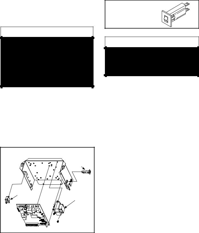
I−UNIT COMPONENTS
G61MP unit components are shown in figure 1. The gas valve, combustion air inducer and burners can be accessed by removing the burner access panel. Electrical components are in the control box (figure 2) found in the blower section.
G61MP units are factory equipped with a bottom return air panel in place. The panel is designed to be field removed as required for bottom air return. Markings are provided for side return air and may be cut out in the field.
ELECTROSTATIC DISCHARGE (ESD)
Precautions and Procedures
3. Circuit Breaker (CB8)
A 24V circuit breaker is also located in the control box. The switch provides overcurrent protection to the transformer (T1). The breaker is rated 3A at 32V. If the current exceeds this limit the breaker will trip and all unit operation will shutdown. The breaker can be manually reset by pressing the button on the face. See figure 3.
CIRCUIT BREAKER CB8
PRESS TO RESET 
 CAUTION
Electrostatic discharge can affect electronic components. Take precautions during furnace installation and service to protect the furnace’s electronic controls. Precautions will help to avoid control exposure to electrostatic discharge by putting the furnace, the control and the technician at the same electrostatic potential. Neutralize electrostatic charge by touching hand and all tools on an unpainted unit surface, such as the gas valve or blower deck, before performing any service procedure.
A−Control Box
1. Control Transformer (T1)
A transformer located in the control box provides power to the low voltage section of the unit. Transformers on all models are rated 40VA with a 120V primary and a 24V secondary.
2. Door Interlock Switch (S51)
A door interlock switch rated 14A at 125VAC is wired in series with line voltage. When the blower door is removed the unit will shut down.
CONTROL BOX G61MP |
|
|
CIRCUIT |
|
BREAKER |
DOOR INTERLOCK |
|
SWITCH |
TRANSFORMER |
|
|
SURELIGHT |
|
CONTROL |
|
BOARD |
|
FIGURE 2
FIGURE 3
 WARNING
Shock hazard.
Disconnect power before servicing. Integrated
Control Board is not field repairable. If control is inoperable, simply replace entire control.
Can cause injury or death. Unsafe operation will result if repair is attempted.
4. Integrated Control Board (A92)
All G61MP units are equipped with the Lennox Two−Stage Integrated control board. The system consists of a ignition control board (figure 4 with control terminal designations in tables 3, 4 and 5) and ignitor (figure 7). The board and ignitor work in combination to ensure furnace ignition and ignitor durability. The board controls all major furnace operations. The board features two LED lights, DS1 and
DS2 for troubleshooting. The board also has two accessory terminals rated at (1) one amp. See table 6 for troubleshooting diagnostic codes.
Electronic Ignition
At the beginning of the heat cycle, SureLight control monitors the first stage and second stage combustion air inducer prove switch. The control will not begin the heating cycle if the first stage prove switch is closed (by−passed). Likewise the control will not begin the second stage heating cycle if the second stage prove switch is closed, and will allow first stage heat only. However if the second stage prove switch closes during the first stage pre−purge, the control will respond to second stage heat. Once the first stage prove switch is determined to be open, the combustion air inducer is energized on low (first stage) heat speed. When the differential in the prove switch is great enough, the prove switch closes and a 15−second pre−purge begins. If the switch is not proven within 2−1/2 minutes, the control goes into Watchguard−Pressure Switch mode for a 5−minute re−set period.
After the 15−second pre−purge period, the SureLight ignitor warms up for 20 seconds after which the gas valve opens for a 4−second trial for ignition. The ignitor energizes during the trial until flame is sensed. If ignition is not proved during the 4−second period, the control will try four more times with an inter purge and warm−up time between trials of 35 sec-
Page 8
onds. After a total of five trials for ignition (including the initial trial), the control goes into Watchguard−Flame Failure mode. After a 60−minute reset period, the control will begin the ignition sequence again.
The SureLight control board has an added feature that prolongs the life of the ignitor. After a successful ignition, the SureLight control utilizes less power to energize the ignitor on successive calls for heat. The control continues to ramp down the voltage to the ignitor until it finds the lowest amount of power that will provide a successful ignition. This amount of power is used for 255 cycles. On the 256th call for heat, the control will again ramp down until the lowest power is determined and the cycle begins again.
Two Stage Operation / Thermostat Selection Jumper
The control can be utilized in two modes: SINGLE−STAGE thermostat or TWO−STAGE thermostat. The thermostat selection jumper E20, located just below dip switches 1 through 4 (figure 4), must be positioned for the particular application. The jumper is factory set on TWO" for use with a two−stage thermostat with two stage heat. Re−position jumper to SINGLE" for use with a single stage thermostat with two stage heat.
While in the single−stage thermostat mode (single jumper setting), the burners will always fire on first−stage heat. The combustion air inducer will operate on low speed and indoor blower will operate on low heat speed. After a 10 minute recognition period, the unit will switch to second stage heat. While in the two−stage thermostat mode (two jumper setting) the burners will fire on first−stage heat. The combustion air inducer will operate on low speed and indoor blower will operate on low heat speed. The unit will switch to second−stage heat on call from the indoor thermostat. If there is a simultaneous call for first and second stage heat, the unit will fire on first stage heat and switch to second stage heat after 30 seconds of operation. See Sequence of Operation flow charts in the back of this manual for more detail.
Dip Switch Settings
Dip Switches 1 and 2 − Heating Fan off Delay − The fan on time of 45 seconds is not adjustable. Fan off time (time that the blower operates after the heat demand has been satisfied) can be adjusted by flipping the dip switches 1 and 2 located on the SureLight integrated control. The unit is shipped with a factory fan off setting of 90 seconds. Fan off time will affect comfort and is adjustable to satisfy individual applications. For customized comfort, monitor the supply air temperature once the heat demand is satisfied. Note the supply air temperature at the instant the blower is de−energized. Adjust the fan−off delay to achieve a supply air temperature between 90° − 110° at the instant the blower is de− energized. (Longer delay times allow for lower air temperature, shorter delay times allow for higher air temperature). See table 1 for dip switch settings.
TABLE 1
Heating Fan Off Delay
Delay (Seconds) |
Switch 1 |
Switch 2 |
|
||
|
|
|
60 |
Off |
Off |
|
|
|
90 |
Off |
On |
|
|
|
120 |
On |
Off |
|
|
|
180 |
On |
On |
Switch 3 − Second Stage Delay (Used with Single−Stage
Thermostat Only) −− This switch is used to determine the second stage on delay when a single−stage thermostat is being used. The switch is factory−set in the ON position, which provides a 10−minute delay before second−stage heat is initiated. If the switch is toggled to the OFF position, it will provide a 15−minute delay before second−stage heat is initiated. This switch is only activated when the thermostat selector jumper is positioned for SINGLE−stage thermostat use.
Switch 4 − Cooling Fan off Delay − The fan on delay time of 2 seconds is not adjustable. Fan off time (time that the blower operates after the cool demand has been satisfied) can be adjusted by flipping dip switch 4. The unit is shipped with a factory fan off setting of 45 seconds. Fan off time will affect comfort and is adjustable to satisfy individual applications. See table 2 for cool fan off time settings.
TABLE 2
Cooling Fan Off Delay
Delay (Seconds) |
Switch 4 |
|
|
2 |
Off |
|
|
45 |
On |
|
|
Diagnostic LED’s (DS1 and DS2)
Two diagnostic LED’S are located on the two−stage integrated control board. See figure 4. These light flashes correspond with the codes detailed in table 6.
Factory Installed Jumper Y1 to Y2
A factory−installed jumper from Y1 to Y2 terminals on the integrated control board terminal strip must be clipped for two−stage cooling.
Page 9
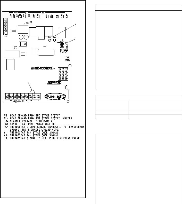
TWO−STAGE INTEGRATED CONTROL BOARD
LEDs
DIP
SWITCHES 1 − 4
W915 FACTORY INSTALLED JUMPER (MUST CLIP FOR 2 STAGE COOL)
THERMOSTAT CONNECTIONS (TB1)
DIP SWITCH(ES) |
FUNCTION |
|
|
1 and 2 |
Blower Off Delay (Heating Mode) |
3 |
Second Stage ON Delay (Single−stage t’stat) |
4 |
Blower Off Delay (Cooling Mode) |
FIGURE 4
TABLE 3
Integrated Control Board Terminals
120VAC Neutral
LINE |
Line |
|
|
XFMR |
Transformer |
|
|
EAC |
Electronic Air Cleaner |
|
|
CIRC |
Indoor Blower |
|
|
HUM |
Humidifier |
|
|
|
120VAC Line |
|
|
HUM |
Humidifier |
|
|
XMFR |
Transformer |
|
|
LINE |
Line |
|
|
PARK |
For Unused Leads |
|
|
COOL |
Cooling Speed |
|
|
EAC |
Electronic Air Cleaner |
|
|
HI HEAT |
HIigh Heat Speed |
|
|
LO HEAT |
Low Heat, Low Cool and Continuous Fan |
|
Speed |
|
|
TABLE 4
Integrated Control Board 5 Pin Terminal
PIN # |
Function |
|
|
1 |
Ignitor |
2Combustion Air Inducer High Speed
3Combustion Air Inducer Low Speed
4 |
Combustion Air Inducer Neutral |
|
|
5 |
Ignitor Neutral |
|
|
TABLE 5
Integrated Control Board 12Pin Terminal
PIN # |
Function |
|
|
1 |
Gas Valve 2nd Stage (High Fire) |
|
|
2 |
Second Stage Prove Switch |
|
|
3 |
Not Used |
|
|
4 |
Ground |
|
|
5 |
24V Hot |
|
|
6 |
Primary Limit In |
|
|
7 |
Gas Valve 1st stage (Low Fire) |
|
|
8 |
Gas Valve Common |
|
|
9 |
24V Neutral |
|
|
10 |
Ground |
|
|
11 |
Primary Limit Out |
|
|
12 |
1st Stage Prove Switch |
|
|
Page 10
|
|
TABLE 6 |
|
|
|
DIAGNOSTIC CODES |
|
|
Diagnostic LEDs are labeled DS1 and DS2. See figure 4 for location of diagnostic LEDs. |
||
|
|
|
|
DS1 |
DS2 |
DESCRIPTION |
|
SIMULTANEOUS |
SIMULTANEOUS |
Power on − Normal operation. |
|
SLOW FLASH |
SLOW FLASH |
Also signaled during cooling and continuous fan. |
|
SIMULTANEOUS |
SIMULTANEOUS |
Normal operation − signaled when heating demand initiated at thermostat. |
|
|
|
||
FAST FLASH |
FAST FLASH |
|
|
SLOW FLASH |
ON |
Primary, secondary, backup secondary or rollout limit switch open. Limits must |
|
close within 3 minutes or unit goes into 1 hour Watchguard. |
|||
|
|
||
|
|
Low prove switch open; |
|
OFF |
SLOW FLASH |
OR: Blocked inlet/exhaust vent; |
|
|
|
OR: Low prove switch closed prior to activation of combustion air inducer. |
|
|
|
|
|
|
|
High prove switch open; |
|
OFF |
FAST FLASH |
OR: Blocked inlet/exhaust vent; |
|
|
|
OR: High prove switch closed prior to activation of combustion air inducer. |
|
|
|
|
|
ALTERNATING |
ALTERNATING |
Watchguard −− burners failed to ignite; OR limit open more than 3 minutes; |
|
OR lost flame sense 5 times in one heating cycle; |
|||
SLOW FLASH |
SLOW FLASH |
||
OR pressure switch opened 5 times in one heating cycle. |
|||
|
|
||
|
|
|
|
SLOW FLASH |
OFF |
Flame sensed without gas valve energized. |
|
ON |
ON |
|
|
ON |
OFF |
Circuit board failure or control wired incorrectly. Check 24 and 115 volts to board. |
|
OFF |
ON |
|
|
|
|
|
|
FAST FLASH |
SLOW FLASH |
Main power polarity reversed. Switch line and neutral. |
|
SLOW FLASH |
FAST FLASH |
Low flame signal. Measures below 0.23 microAmps. Replace flame sense rod. |
|
|
|
The following conditions are sensed during the ignitor warm−up period only: |
|
|
|
1) Improper main ground; |
|
ALTERNATING |
ALTERNATING |
2) Broken ignitor; OR: Open ignitor circuit; |
|
FAST FLASH |
FAST FLASH |
3) Line voltage below 75 volts. |
|
|
|
(If voltage lower than 75 volts prior to ignitor warm-up, control will signal waiting on |
|
|
|
call from thermostat, and will not respond. |
|
|
|
|
|
NOTE − Slow flash rate equals 1 Hz (one flash per second). Fast flash rate equals 3 Hz (three flashes per second).
Low flame sense current = 0.17−0.22 microAmps.
B−Blower Compartment
1. Blower Motor (B3) and Capacitor (C4)
All G61MP units use direct drive blower motors. All motors are 120V permanent split capacitor motors to ensure maximum efficiency. Ratings for capacitors will be on motor nameplate. See SPECIFICATIONS section for motor specifications.
NOTE − Shafts on 1 HP motors have 2 flat sides and are matched with blower wheels with 2 set screws.
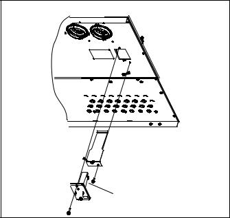
2. Secondary Limit Controls (S21)
The secondary limits (S21) on G61MP units are located in the blower compartment on the back side of the blower housing.
See figure 5. All G61MP units are equipped with two secondary limts. When excess heat is sensed in the blower compartment, the limit will open. If the limit is open, the furnace control energizes the supply air blower and closes the gas valve. The limit automatically resets when unit temperature returns to normal. The switch is factory set to open at 125°F and cannot be adjusted.
SUPPLY AIR BLOWER
AND SECONDARY LIMITS
SECONDARY
LIMIT (S)
MOTOR/BLOWER ASSEMBLY
CAPACITOR
To Remove Blower From Unit: Disconnect Power, Remove Control Box, Remove Bolts and Unplug Motor Wires From Control Board.
Then Slide Out Front of Unit.
FIGURE 5
Page 11
C−Heating Components
3. Flame Sensor
A flame sensor is located on the left side of the burner support. See figure 6. The sensor is mounted through the bottom of the burner box and the tip protrudes into the flame envelope of the left−most burner. The sensor can be removed for service without removing any part of the burners. During operation, flame is sensed by current passed through the flame and sensing electrode. The SureLight control allows the gas valve to remain open as long as flame signal is sensed.
4. Ignitor
The SureLight ignitor is made of durable silicon nitride. Ignitor longevity is enhanced by controlling voltage to the ignitor. The board finds the lowest ignitor temperature which will successfully light the burner, thus increasing the life of the ignitor. Due to this feature of the board, voltage cannot be measured so ignitor must be ohmed. Ohme value should be 10.9 to 19.7. See 7 for ignitor location.
NOTE − The G61MP furnace contains electronic components that are polarity sensitive. Make sure that the furnace is wired correctly and is properly grounded.
NORMAL FLAME SIGNAL > 0.23 MICROAMPS
LOW FLAME SIGNAL |
< 0.22 MICROAMPS |
DROP OUT SIGNAL |
= 0.16 MICROAMPS |
5/16"
FIGURE 6
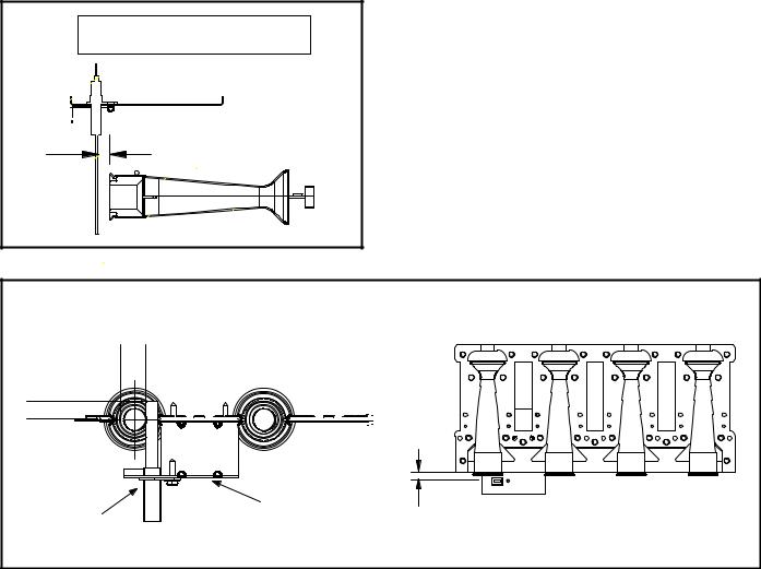
5. Burners (Figure 7)
All units use inshot burners. Burners are factory set and do not require adjustment. The manifold brackets are slotted so burners can be removed as an assembly for service. Burner maintenance and service is detailed in the MAINTENANCE section of this manual. Each burner uses an orifice which is precisely matched to the burner input and is threaded into the burner manifold. All G61MP natural gas units are fitted with
.089" sized orifices. See SPECIFICATIONS" tables for LP kits and high altitude.
A flame retention ring in the end of each burner maintains correct flame length and shape and keeps the flame from lifting off the burner head. In addition, the burner entrance to each clamshell is fitted with a corbel cup (orifice) used to direct the flow of combustion products.
|
SureLight Ignitor Location |
|
5/8" |
MEASUREMENT IS TO I.D. |
|
OF RETENTION RING |
|
|
13/32’ |
|
|
|
5/16" |
|
IGNITOR |
BRACKET |
|
|
|
|
BURNERS FRONT VIEW |
BURNERS TOP VIEW |
|
FIGURE 7
Page 12
6. Clamshell Heat Exchanger
G61MP units use an aluminized steel primary and stainless steel secondary heat exchanger assembly. Heat is transferred to the air stream from all surfaces of the heat exchanger. The shape of the heat exchanger ensures maximum efficiency.
The combustion air inducer pulls fresh air through the air intake box. This air is mixed with gas in the burner venturi and at the corbel orifices. The gas / air mixture is then burned at the entrance of each clamshell. Combustion gases are then pulled through the primary and secondary heat exchangers and exhausted out the exhaust vent pipe.
7. Flame Rollout Switches (S47)
Flame rollout switch S47 is a high temperature limit located on each side of the burner box. Each furnace is equipped with two identical switches. The limit is a N.C. SPST manu- al-reset limit connected in series with the primary limit S10. When S47 senses rollout, the circuit breaks and the ignition control immediately stops ignition and closes the gas valve.
If unit is running and flame rollout is detected, the gas valve will close and ignition control will be disabled. Rollout can be caused by a blocked heat exchanger, flue or lack of combustion air. The switch is factory set to trip (open) at 250°F and cannot be adjusted. The switch can be manually reset. To manually reset a tripped switch, push the reset button located on the control.
8. Primary Limit Control (S10)
Figure 8 shows the primary limit (S10) used on G61MP units located in the heating vestibule panel. S10 is provided with a shield on some models (figure 8) and must not be removed. Note orientation of shield and limit if limit is replaced. When excess heat is sensed in the heat exchanger, the limit will open.
Once the limit opens, the furnace control energizes the supply air blower and de−energizes the gas valve. The limit automatically resets when unit temperature returns to normal. The switch is factory set and cannot be adjusted.
9.Backup Secondary Limit Control (S113) (G61MP−090, 110, 135 only)
Backup secondary limit control S113 is a N.C. auto−reset switch located on the combustion air inducer. S113 acts as a backup to primary limit S10 in the event of an indoor blower failure. S113 contacts open when temperature on the CAI reaches 142°.
10. Gas Valve (GV1)
The G61MP uses a two−stage gas valve manufactured by Honeywell (figure 35) or White Rodgers (figure 36). The valves are internally redundant to assure safety shut−off. If the gas valve must be replaced, the same type valve must be used.
24VAC terminals and gas control knob or switch are located on the valve. All terminals on the gas valve are connected to wires from the electronic ignition control. 24V applied to the terminals energizes the valve.
Inlet and outlet pressure taps are located on the valve. A regulator adjustment screw is located on the valve.
LPG change over kit s are available from Lennox. Kits include burner orifices and a gas valve regulator conversion kit.
The burner box is sealed and operates under a negative pressure. A pressure hose is connected from the burner box to the gas valve. The gas valve senses the pressure in the burner box and changes gas valve outlet (manifold) pressure based on changes in the burner box pressure.
The intent is to compensate for different vent configurations which can greatly affect the rate of the unit.
PRIMARY LIMIT LOCATION
 limit shield 090, −110 and
−135 only
limit faces shield
FIGURE 8
11. Combustion Air Inducer Prove Switch (S18)
All G61MP units are equipped with combustion air prove switches located on the combustion air inducer housing.
G61MP−045 and −070 (figure 10) units have two combustion air proving switches. G61MP−090, −110 and −135 units are equipped with two dual prove switch assemblies" consisting of two switches acting as one. See figure 9. The switches are connected to the cold end header box by means of a flexible hose that monitors negative air pressure in the cold end header box.
The switches are a single-pole single-throw proving switch electrically connected to the furnace control. The purpose of the switch is to prevent burner operation if the combustion air inducer is not operating or if the flue becomes obstructed.
Page 13
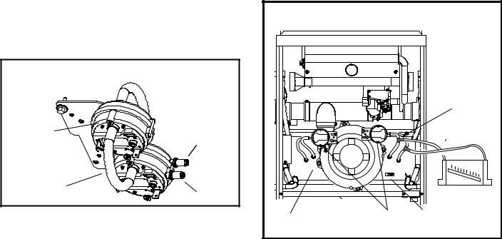
On heat demand (first or second stage) the switch senses that the combustion air inducer is operating. It closes a circuit to the furnace control when pressure inside the cold end header box decreases to a certain set point.
Set points vary depending on unit size. See tables 8, 9 and 10. The pressure sensed by the switch is negative. If the air intake vent pipe or outlet vent pipe becomes obstructed during operation, the switch senses a change of negative pressure and opens the circuit to the furnace control and gas valve. A bleed port on the switch allows relatively dry air in the vestibule to purge switch tubing, to prevent condensate build up.
The switch is factory set and is not field adjustable. It is a safety shut-down control in the furnace and must not be by− passed for any reason. If switch is closed or by−passed, the control will not initiate ignition at start up.
DUAL COMBUSTION AIR PROVE SWITCH
G61MP−090, −110 & −135
first stage |
negative |
|
pressure |
||
|
second stage
positive pressure
FIGURE 9
To troubleshoot the prove switches, temporarily jumper them.
The unit will not fire with the switches jumpered. Therefore, the prove switches must be bypassed after the combustion air inducer is activated. This will determine if the prove switches and furnace are operating properly. However, this may not indicate if the sealed combustion system is operating properly.
Checks of pressure differential can aid in troubleshooting. When measuring the pressure differential, readings should be taken at the prove switch. Lack of differential usually indicates problems in the intake or exhaust piping, but may indicate problems in the heat exchanger, condensing coil, header boxes, combustion inducer or other components.
Measuring pressure differential
The differential pressure is the difference in pressure measured across the cold end header box orifice.
1 − Remove thermostat demand and allow unit to cycle off.
2 − |
Install a tee in the negative (−) line and a tee in the positive |
|
(+) line running from one of the prove switches to the cold |
|
end header box. |
3 − |
Install a manometer with hose from the negative (−) |
|
side of the manometer to the tee installed in the nega- |
tive (−) line and with hose from the positive (+) side of the manometer to the tee in the positive (+) line.
NOTE − Both sides of the cold end header box are negative.
However the (+) port reads less negative pressure than the
(−) port.
CAI & COLD END HEADER BOX ASSEMBLY |
|
(−045 & 070 SHOWN) |
|
|
Install tee’s in the |
|
negative line and |
|
positive line then |
|
connect hoses to |
|
manometer. |
_ + |
+ _ |
cold end header box |
prove switches orifice size |
FIGURE 10
4 − Operate unit and observe manometer reading. Readings will change as heat exchanger warms.
a.Take one reading immediately after start-up.
b.Take a second reading after unit has reached steady state (approximately 5 minutes). This will be the pressure differential.
The pressure differential should be greater than those listed in table 8, 9 or 10.
5 − Remove thermostat demand and allow to cycle off.
6 − Remove manometer and tee’s. Reinstall combustion air sensing hoses to the prove switch.
7 − Repeat steps 1 through 6 for the other prove switch.
Page 14
12. Combustion Air Inducer (B6)
All G61MP units use a combustion air inducer to move air through the burners and heat exchanger during heating operation. The blower uses a PSC 120VAC motor. The motor operates during all heating operation and is controlled by the ignition control A3. Blower operates continuously while there is a call for heat. The burner ignition control will not proceed with the ignition sequence until combustion air inducer operation is sensed by the proving switches.
The CAI is installed on the cold end header box. The cold end header box is a single piece made of hard plastic. The box has an internal channel where the combustion air inducer creates negative pressure at unit start up. The channel contains an orifice used to regulate flow created by the CAI. The box has pressure taps for the CAI prove switch hoses.
The prove switches measure the pressures across the CAI orifice or difference in the channel and the box. A window is provided on the bottom right hand side of the box to indicate orifice size. See figure 10. See table 7 for orifice size per unit. If replacement is necessary the gaskets used to seal the box to the vestbule panel and the CAI to the box, must also be replaced.
|
TABLE 7 |
|
|
|
|
G61MP Unit |
|
C.A.I. Orifice Size |
|
|
|
−045 |
|
.719" |
|
|
|
−070 |
|
.938" |
|
|
|
−090 |
|
1.063" |
|
|
|
−110 |
|
1.313" |
|
|
|
−135 |
|
1.688" |
|
|
|
TABLE 8 0’ to 4500’
G61MP Unit |
Set Point |
Set Point |
|
Second Stage |
First Stage |
||
|
|||
|
|
|
|
−045 |
0.95" |
0.95" |
|
|
|||
−070 |
|||
|
|
||
|
|
|
|
−090 |
0.85" |
0.50" |
|
|
|||
−110 |
|||
|
|
||
|
|
|
|
−135 |
0.60" |
0.35" |
|
|
|
|
|
|
TABLE 9* |
|
|
|
4501’ to 7500’ |
|
|
|
|
|
|
G61MP Unit |
Set Point |
Set Point |
|
Second Stage |
First Stage |
||
|
|||
|
|
|
|
−045 |
0.95" |
0.95" |
|
|
|||
−070 |
|||
|
|
||
|
|
|
|
−090 |
0.75" |
0.50" |
|
|
|
|
|
−110 |
0.85" |
0.50" |
|
|
|
|
|
−135 |
0.55" |
0.35" |
|
|
|
|
*Unit may require conversion kit at this altitude. See High Altitude table.
TABLE 10* 7501’ to 10,000’
G61MP Unit |
Set Point |
Set Point |
|
Second Stage |
First Stage |
||
|
|||
|
|
|
|
−045 |
0.95" |
0.95" |
|
|
|
|
|
−070 |
0.85" |
0.85" |
|
|
|
|
|
−090 |
0.60" |
0.35" |
|
|
|
|
|
−110 |
0.85" |
0.50" |
|
|
|
|
|
−135 |
0.55" |
0.35" |
|
|
|
|
*Unit may require conversion kit at this altitude. See High Altitude table.
Page 15
II−PLACEMENT AND INSTALLATION
TABLE 11
OUTDOOR TERMINATION KITS AND CORRESPONDING EQUIVALENCIES
|
|
|
|
Vent Pipe Length Equivalency (feet) |
|
|
|
||||
|
|
|
|
|
|
|
|
|
|
|
|
|
|
Outdoor |
Outdoor |
|
|
|
|
|
2" Wall |
|
|
|
VENT |
Exhaust |
Exhaust |
1−1/2" |
2" Con- |
3" Con- |
|
|
|
||
|
2" Wall |
3" Wall |
Kit with |
2" Wall |
|||||||
|
Accelerator |
Accelerator |
Concen- |
centric |
centric |
||||||
UNIT |
PIPE |
||||||||||
Plate Kit |
Plate Kit |
Vent Ex- |
Ring Kit |
||||||||
MODEL |
DIA. |
(Dia. X |
(Dia. X |
tric Kit |
Kit |
Kit |
|||||
|
|
tension |
|
||||||||
|
(in.) |
Length) |
Length) |
|
|
|
|
|
|
||
|
|
|
|
|
|
|
|
||||
|
|
|
|
|
|
|
|
|
|
|
|
|
|
1−1/2" X 12" |
2" X 12" |
71M80 |
60M29 |
60L46 |
22G44 |
44J40 |
30G28 |
15F74 |
|
|
|
81J20 |
|||||||||
|
|
|
|
|
|
|
|
|
|
||
|
|
|
|
|
|
|
|
|
|
|
|
|
2 |
4 |
Not |
12 |
Not |
Not |
4 |
4* |
4 |
4 |
|
|
Allowed |
Allowed |
Allowed |
||||||||
|
|
|
|
|
|
|
|
||||
|
2−1/2 |
5 |
Not |
15 |
Not |
Not |
5 |
5* |
5 |
5 |
|
|
Allowed |
Allowed |
Allowed |
||||||||
36B−045 |
|
|
|
|
|
|
|
||||
3 |
7 |
Not |
21 |
Not |
Not |
7 |
7* |
7 |
7 |
||
|
|||||||||||
|
Allowed |
Allowed |
Allowed |
||||||||
|
|
|
|
|
|
|
|
||||
|
4 |
14 |
Not |
42 |
Not |
Not |
14 |
14* |
14 |
14 |
|
|
Allowed |
Allowed |
Allowed |
||||||||
|
|
|
|
|
|
|
|
||||
|
2 |
4 |
Not |
12 |
Not |
Not |
4 |
4* |
4 |
4 |
|
|
Allowed |
Allowed |
Allowed |
||||||||
|
|
|
|
|
|
|
|
||||
|
2−1/2 |
5 |
Not |
15 |
Not |
Not |
5 |
5* |
5 |
5 |
|
|
Allowed |
Allowed |
Allowed |
||||||||
36B−070 |
|
|
|
|
|
|
|
||||
3 |
8 |
Not |
24 |
Not |
Not |
8 |
8* |
8 |
8 |
||
|
|||||||||||
|
Allowed |
Allowed |
Allowed |
||||||||
|
|
|
|
|
|
|
|
||||
|
4 |
14 |
Not |
42 |
Not |
Not |
14 |
14* |
14 |
14 |
|
|
Allowed |
Allowed |
Allowed |
||||||||
|
|
|
|
|
|
|
|
||||
|
2 |
Not |
1 |
Not |
3 |
3 |
Not |
1 |
Not |
1** |
|
|
Allowed |
Allowed |
Allowed |
Allowed |
|||||||
|
|
|
|
|
|
|
|||||
|
2−1/2 |
Not |
2 |
Not |
6 |
6 |
Not |
2 |
Not |
2** |
|
|
Allowed |
Allowed |
Allowed |
Allowed |
|||||||
60C−090 |
|
|
|
|
|
|
|||||
3 |
Not |
2 |
Not |
6 |
6 |
Not |
2 |
Not |
2** |
||
|
|||||||||||
|
Allowed |
Allowed |
Allowed |
Allowed |
|||||||
|
|
|
|
|
|
|
|||||
|
4 |
Not |
4 |
Not |
12 |
12 |
Not |
4 |
Not |
4** |
|
|
Allowed |
Allowed |
Allowed |
Allowed |
|||||||
|
|
|
|
|
|
|
|||||
|
2−1/2 |
Not |
2 |
Not |
6 |
6 |
Not |
2 |
Not |
2*** |
|
|
Allowed |
Allowed |
Allowed |
Allowed |
|||||||
|
|
|
|
|
|
|
|||||
60C−110 |
3 |
Not |
2 |
Not |
6 |
6 |
Not |
2 |
Not |
2*** |
|
Allowed |
Allowed |
Allowed |
Allowed |
||||||||
|
|
|
|
|
|
|
|||||
|
4 |
Not |
4 |
Not |
12 |
12 |
Not |
4 |
Not |
4*** |
|
|
Allowed |
Allowed |
Allowed |
Allowed |
|||||||
|
|
|
|
|
|
|
|||||
|
3 |
Not |
6 |
Not |
Not |
15 |
Not |
6 |
Not |
6*** |
|
|
Allowed |
Allowed |
Allowed |
Allowed |
Allowed |
||||||
60D−135 |
|
|
|
|
|
||||||
4 |
Not |
10 |
Not |
Not |
25 |
Not |
10 |
Not |
10*** |
||
|
|||||||||||
|
Allowed |
Allowed |
Allowed |
Allowed |
Allowed |
||||||
|
|
|
|
|
|
||||||
*Requires field−provided and installed 1−1/2" exhaust accelerator. **Requires field−provided and installed 2" exhaust accelerator.
***For use only in non−direct vent applications, when snow riser is
not required. Requires field−provided and installed 2" exhaust accelerator.
Page 16
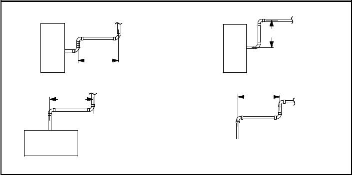
A−Vent Piping Guidelines
The G61MP can be installed as either a Non−Direct Vent or a Direct Vent gas central furnace.
NOTE − In Non-Direct Vent installations, combustion air is taken from indoors and flue gases are discharged outdoors.
In Direct Vent installations, combustion air is taken from outdoors and flue gases are discharged outdoors.
Intake and exhaust pipe sizing in Direct Vent applications and exhaust pipe sizing in Non-Direct Vent applications −−
Size pipe according to tables 12 and 13. Table 12 lists the minimum equivalent vent pipe lengths permitted. Table 13 lists the maximum equivalent pipe lengths permitted.
Maximum vent length is defined as:
Total length (linear feet) of pipe,
Plus Equivalent length (feet) of fittings,
Plus Equivalent length (feet) of termination.
NOTE − Include ALL pipe and ALL fittings, both in doors and outdoors.
Regardless of the diameter of pipe used, the standard roof and wall terminations described in section Exhaust Piping
Terminations should be used. Exhaust vent termination pipe is sized to optimize the velocity of the exhaust gas as it exits the termination. Refer to table 14.
*NOTE − The exhaust pipe should be offset a minimum of 12 inches to avoid the possibility of water droplets being released from the exhaust termination. The minimum exhaust vent length is 15 ft. Shorter exhaust vent lengths may result in the discharge of water droplets from the exhaust termination, in spite of the 12−inch vertical offset.
Each 90° elbow (including those provided with the furnace) of any diameter is equivalent to 5 feet (1.52m) of vent pipe of the same diameter. Two 45° elbows are equivalent to one 90° elbow of the same diameter. One 45° elbow is equal to 2.5 feet (.76m) of vent pipe of the same diameter. In some applications which permit the use of several different sizes of vent pipe, a combination vent pipe may be used. Contact the Application Department for assistance in sizing vent pipe in these applications.
NOTE − The flue collar on all models is sized to accommodate 2" Schedule 40 flue pipe. When vent pipe which is larger than 2" must be used in an upflow application, a 2" elbow must be applied at the flue collar in order to properly transition to the larger diameter flue pipe. This elbow must be added to the elbow count used to determine acceptable vent lengths. Assign an equivalent feet value to this elbow according to the larger size pipe being used. Contact the Application Department for more information concerning sizing of vent systems which include multiple pipe sizes.
|
Exhaust Pipe Offset |
|
12" Min. |
12" Min. |
|
Upflow and Downflow Application |
Upflow and Downflow Application |
Rooftop Termination |
Side Wall Termination |
12" Min. |
12" Min. |
|
Horizontal Application |
|
Horizontal Application |
Rooftop Termination |
|
Side Wall Termination |
|
|
|
FIGURE 11
Page 17
 Loading...