


INSTALLATION AND OPERATION
MANUAL
FREESTANDING VENTED GAS FIRED ROOM HEATERS
|
L20 DVF-2 shown with optional gold door and brickaded interior |
|
|
|
Models: L20 BF-2 (B-Vent) and L20 DVF-2 (Direct-Vent) |
|
RETAIN THIS MANUAL FOR FUTURE REFERENCE |
|
P/N 775,021M Rev. C, 8/04 |
|
Model L20 DVF-2 may be installed in an aftermarket permanently located, |
Report #189122-1027389 |
manufactured (mobile) home, where not prohibited by local codes |
|
|
WARNING: IF THE INFORMATION IN THIS MANUAL IS NOT FOLLOWED EXACTLY, A FIRE OR EXPLOSION MAY RESULT CAUSING PROPERTY DAMAGE, PERSONAL INJURY OR LOSS OF LIFE.
FOR YOUR SAFETY: Do not store or use gasoline or other flammable vapors or liquids in the vicinity of this or any other appliance.
FOR YOUR SAFETY: What to do if you smell gas:
•DO NOT light any appliance.
•DO NOT touch any electrical switches.
•Do not use any phone in your building.
•Immediately call your gas supplier from a neighbor’s phone. Follow your gas suppliers instructions.
•If your gas supplier cannot be reached, call the fire department.
Installation and service must be performed by a qualified installer, service agency or the gas supplier.
AVERTISSEMENT: ASSUREZ-VOUS DE BIEN SUIVRE LES INSTRUCTIONS DONNÉ DANS CETTE NOTICE POUR RÉDUIRE AU MINIMUM LE RISQUE D’INCENDIE OU POUR ÉVITER TOUT DOMMAGE MATÉRIEL, TOUTE BLESSURE OU LA MORT.
POUR VOTRE SÉCURITÉ: Ne pas entreposer ni utiliser d’essence ni d’autre vapeurs ou liquides inflammables dans le voisinage de cet appareil ou de tout autre appareil.
POUR VOTRE SÉCURITÉ: Que faire si vous sentez une odeur de gaz:
•Ne pas tenter d’allumer d’appareil.
•Ne touchez à aucun interrupteur. Ne pas vous servir des téléphones se trouvant dans le batiment où vous vous trouvez.
•Evacuez la piéce, le bâtiment ou la zone.
•Appelez immédiatement votre fournisseur de gaz depuis un voisin. Suivez les instructions du fournisseur.
•Si vous ne pouvez rejoindre le fournisseur de gaz, appelez le service dos incendies.
L’installation et service doit être exécuté par un qualifié installeur, agence de service ou le fournisseur de gaz.
IMPORTANT WARNINGS / CAUTIONS
CAUTION: READ THIS MANUAL THOROUGHLY BEFORE STARTING INSTALLATION. FOR YOUR SAFETY, FOLLOW THE INSTALLATION, OPERATION AND MAINTENANCE INSTRUCTIONS EXACTLY WITHOUT DEVIATION. FAILURE TO FOLLOW THESE INSTRUCTIONS MAY RESULT IN A POSSIBLE FIRE HAZARD AND MAY VOID THE WARRANTY. IF THIS APPLIANCE IS NOT PROPERLY INSTALLED, A HOUSE FIRE MAY RESULT. CONTACT LOCAL BUILDING OR FIRE OFFICIALS ABOUT RESTRICTIONS AND INSTALLATION INSPECTION IN YOUR AREA.
1.WARNING: IMPROPER ASSEMBLY, INSTALLATION, ADJUSTMENT, ALTERATION, SERVICE OR MAINTENANCE CAN CAUSE INJURY AND / OR PROPERTY DAMAGE. INSTALLATION AND SERVICE MUST BE PERFORMED BY A QUALIFIED INSTALLER, SERVICE AGENCY OR THE GAS SUPPLIER. EXCEPT WHEN COMPLYING WITH LOCAL CODES, ANY DEVIATION FROM THE INSTALLATION AND / OR OPERATING INSTRUCTIONS CONTAINED IN THIS MANUAL WILL VOID THE APPLIANCE WARRANTY AND MAY BE HAZARDOUS.
2.DUE TO HIGH TEMPERATURES, THIS APPLIANCE SHOULD BE LOCATED OUT OF TRAFFIC AND AWAY FROM FURNITURE, DRAPERIES AND NOT IN WINDY OR DRAFTY AREAS.
3.THE APPLIANCE MUST NOT BE CONNECTED TO A CHIMNEY FLUE SERVING A SEPARATE SOLID-FUEL BURNING APPLIANCE.
4.MODEL L20 DVF-2 IS EQUIPPED WITH A RELIEF DOOR IN CASE OF DELAYED IGNITION BLOWBACK. IF THE RELIEF DOOR OPENS, REMOVE BACK PANEL AND INSPECT FOR GASKET DAMAGE. IF NECESSARY, REPLACE WITH FACTORY SUPPLIED GASKET ONLY. CONFIRM RELIEF DOOR IS CLOSED AND PROPERLY SEATED, THEN REPLACE BACK PANEL.
5.CAUTION: HOT WHILE IN OPERATION. AN APPLIANCE HOT ENOUGH TO WARM YOUR HOME CAN SEVERELY BURN ANYONE TOUCHING IT. KEEP CHILDREN, CLOTHING AND FURNITURE AWAY. CONTACT MAY CAUSE SKIN BURNS. DO NOT LET CHILDREN TOUCH THE APPLIANCE. TRAIN THEM TO STAY A SAFE DISTANCE FROM THE UNIT.
6.DO NOT PLACE CLOTHING OR OTHER FLAMMABLE MATERIAL ON OR NEAR THE GAS APPLIANCE. THE MINIMUM CLEARANCES MUST BE MAINTAINED FOR ALL COMBUSTIBLE SURFACES AND MATERIALS INCLUDING; FURNITURE, CARPET, DRAPES, CLOTHING, WOOD, PAPERS, ETC.
7.NEVER SEAL THE OPENING AT THE REAR OF THE STOVE.
8.DO NOT CONNECT 110-12 VAC (RESIDENTIAL LINE VOLTAGE) TO THE GAS CONTROL VALVE OR CONTROL WIRING SYSTEM OF THE UNIT.
9.ANY SAFETY SCREEN OR GUARD REMOVED FOR SERVICING MUST BE REPLACED PRIOR TO OPERATING THE APPLIANCE.
10.WARNING: USE ONLY THE GLASS DOOR CERTIFIED WITH THIS APPLIANCE. EXERCISE CAUTION TO PROTECT GLASS FROM IMPACT. DO NOT OPERATE THE APPLIANCE WITH BROKEN GLASS OR USE SUBSTITUTE MATERIALS.
11.DO NOT USE THIS APPLIANCE IF ANY PART HAS BEEN UNDER WATER. IMMEDIATELY CALL A QUALIFIED SERVICE TECHNICIAN TO INSPECT THE APPLIANCE AND REPLACE ANY PART OF THE CONTROL SYSTEM AND GAS CONTROL WHICH HAS BEEN UNDER WATER.
12.DO NOT BURN WOOD OR OTHER MATERIAL IN THIS HEATER.
13.WARNING: THE APPLIANCE AREA MUST BE KEPT CLEAR AND FREE FROM COMBUSTIBLE MATERIALS, GASOLINE AND OTHER FLAMMABLE VAPORS AND LIQUIDS.
14.DO NOT USE A BLOWER INSERT, HEAT EXCHANGER INSERT OR OTHER ACCESSORY NOT APPROVED FOR USE WITH THIS APPLIANCE.
15.THIS APPLIANCE IS NOT FOR USE WITH AIR FILTERS.
16.ANY CHANGE TO THIS HEATER OR ITS CONTROLS CAN BE DANGEROUS.
17.THIS APPLIANCE SHOULD BE INSPECTED AND MAINTAINED AT LEAST ANNUALLY BY A PROFESSIONAL SERVICE PERSON. MORE FREQUENT CLEANING MAY BE REQUIRED DUE TO EXCESSIVE LINT FROM CARPETING, BEDDING MATERIAL, ETC. IT IS IMPERATIVE THAT CONTROL COMPARTMENTS, BURNERS AND CIRCULATING AIR PASSAGEWAYS OF THE APPLIANCE BE KEPT CLEAN.
18.THIS APPLIANCE IS ONLY FOR USE WITH THE TYPE OF GAS INDICATED ON THE RATING LABEL (LOCATED INSIDE CONTROL PANEL). THIS APPLIANCE IS NOT CONVERTIBLE FOR USE WITH OTHER FUEL UNLESS A CERTIFIED KIT IS USED.
19.CAUTION: UNDER NO CIRCUMSTANCES SHOULD THESE APPLIANCES BE VENTED TO OTHER ROOMS OR BUILDINGS. THESE APPLIANCES MUST ONLY BE VENTED TO THE OUTSIDE. VENT TERMINATIONS SHALL NOT BE RECESSED INTO A WALL OR SIDING.
20.WARNING: THESE APPLIANCES MUST BE PROPERLY CONNECTED TO A VENTING SYSTEM. OPERATION OF THESE GAS APPLIANCES WHEN NOT CONNECTED TO A PROPERLY INSTALLED AND MAINTAINED VENTING SYSTEM CAN RESULT IN CARBON MONOXIDE (CO) POISONING AND POSSIBLE DEATH.
21.WARNING: DO NOT MODIFY THE VENTING SYSTEM, APPLIANCE, OR CONTROLS IN ANY WAY. BE ADVISED, ANY MODIFICATION CAN BE DANGEROUS.
22.IMPORTANT: DO NOT EXCEED THE MAXIMUM HORIZONTAL RUNS ALLOWED.
23.SAVE THESE INSTRUCTIONS.
PAGE 2

TABLE OF CONTENTS |
|
Important Warnings ........................................................ |
2 |
Testing / Listing, Using this Manual ................................. |
3 |
Planning Your Installation .............................................. |
4-6 |
Manufactured (Mobil) Home Requirements....................... |
6 |
Installation ................................................................... |
7-15 |
Care and Operation..................................................... |
16-17 |
Propane Conversion ................................................... |
18-19 |
Maintenance ............................................................... |
20-21 |
Wiring Diagrams ............................................................. |
22 |
Troubleshooting ......................................................... |
23-24 |
Replacement Parts / Optional Accessories....................... |
25 |
Specifications ............................................................. |
27-28 |
Safety / Listing Labels ................................................ |
29-30 |
Ownership Record and Service Log................................. |
31 |
TESTING / LISTING
This appliance is tested and certified as safe for residential use by an internationally recognized testing and certification agency. The safety tests are conducted in accordance with American National Standards Institute (ANSI) requirements. These appliances are tested, certified, and listed by the CSA, AGA, CGA to ANSI Z21.88a - 2003 Vented Gas Fireplace Heaters and CSA 2.33a - M98 - 2003 Vented Gas Fireplace Heaters.
APPROVED VENTING:
L20 DVF-2 Listed for installation with Security Secure Vent chimney or Simpson Dura Vent brand chimney only. Other brands may not be used. See pages 8 and 9.
L20 BF-2 May be vented with any listed class B chimney components installed in accordance with manufacturers instructions. See page 11.
CONGRATULATIONS ON THE PURCHASE OF YOUR NEW GAS APPLIANCE MANUFACTURED BY LENNOX HEARTH PRODUCTS.
When you purchased your new gas fired heater, you joined the ranks of thousands of concerned individuals whose answer to their home heating needs reflects their concern for aesthetics, efficiency and our environment. We extend our continued support to help you achieve the maximum benefit and enjoyment available from your new gas fired heater.
It is our goal at Lennox Hearth Products to provide you, our valued customer, with an appliance that will ensure you years of trouble free warmth and pleasure.
Thank you for selecting a Lennox Hearth Products gas fired heater as the answer to your home heating needs.
Sincerely,
All of us at Lennox Hearth Products
PACKAGING LIST
This appliance is packaged with an accessory package, which contains the following:
One - Installation and operation instructions manual. One - Warranty.
One - Log set and embers. One - LP conversion kit.
One - 9 ft. electrical power cord.
USING THIS MANUAL
Please read and carefully follow all of the instructions found in this manual. Please pay special attention to the safety instructions provided in this manual. Following the Homeowner’s Care and Operation Instructions included here will assure that you have many years of dependable and enjoyable service from your appliance.
PAGE 3
PLANNING YOUR INSTALLATION
LOCAL AND NATIONAL CODE REQUIREMENTS
The installation of these appliances must conform with local codes or, in the absence of local codes, with the National Fuel Gas Code, (for USA) NFPA 54 / ANSI Z223.1 - latest edition.
Air Circulation Blower: The blower electrical power cord must be electrically grounded per local codes or per electrical codes:
In USA, NEC, ANSI / NFPA 70 - latest edition. In Canada, CSA C22.1
WARNINGS
ELECTRICAL GROUNDING INSTRUCTIONS. THIS APPLIANCE IS EQUIPPED WITH A THREE-PRONG (GROUNDING) PLUG FOR YOUR PROTECTION AGAINST SHOCK HAZARD AND SHOULD BE PLUGGED DIRECTLY INTO A PROPERLY GROUNDED THREE-PRONG RECEPTACLE. DO NOT CUT OR REMOVE THE GROUNDING PRONG FROM THIS PLUG.
WARNING: TO AVOID ELECTRICAL SHOCK, ALWAYS ENSURE THAT THE POWER CORD IS UNPLUGGED (I.E., THERE IS NO ELECTRICAL POWER TO THE CIRCULATION BLOWER) BEFORE HANDLING THE CIRCULATION BLOWER OR PERFORMING ANY WORK ON THE APPLIANCE.
High Altitude: Gas inputs shown are for elevations up to 4500 feet. For elevations above 4500 feet, contact your gas supplier or qualified service technician regarding the necessary deration of appliance (deration: replacing burner orifice with a smaller one to reduce input). Ratings must be reduced at the rate of 4 percent for each 1,000 feet above sea level. Refer to (for USA) NFPA 54 / ANSI Z223.1 - latest edition for orifice resizing.
TOOL / EQUIPMENT LIST
The following tools and equipment are recommended for completing the partial assembly required when the appliance is installed:
•7/16”, 3/4” open end wrenchs.
•1/4”, 3/8” nut drivers.
•Pipe wrench.
•Phillips head screw driver.
•Flat head screw driver.
•Pipe sealant compound.
•Leak test fluid “U” tube manometer or pressure gauge (0 - 16” (inches water column) H2O scale.
GAS PRESSURE (WC = Water Column)
Minimum inlet gas supply pressure for the purpose of input adjustment:
Natural Gas - 4.5” WC min. – 7.0” WC max.
Propane (LP) - 11” WC min - 13.0” WC max.
Manifold gas supply pressure: |
|
|
LOW |
|
HIGH |
Natural Gas - 1.8” + / -.3” WC |
(to) |
3.5” + / -.3” WC |
17,000 BTU / hr |
|
26,000 BTU / hr |
Propane (LP) 6.6” + / -.3” WC |
(to) |
10” + / -.3” WC |
17,000 BTU / hr |
|
24,000 BTU / hr |
Note: ” WC = Inches Water Column
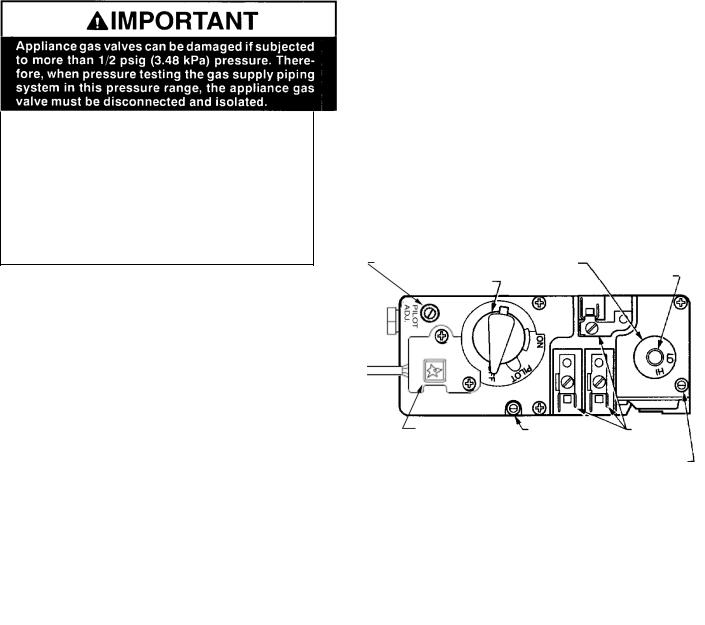
PRESSURE TAPS
Gas Inlet Pressure Tap - Located on bottom left of gas valve.
Gas Outlet (manifold) pressure tap - Located on bottom right of gas valve.
Gas Control Valve
Pilot Adjustment Screw |
Convertible HI/LO |
Regulator |
Regulator |
||
Gas Control Knob |
|
Cap |
Piezo Igniter |
Inlet |
Wiring |
|
Pressure |
Terminals |
|
Tap |
Outlet Pressure Tap |
|
|
Pressure Testing: See Pressure Testing on page 12.
PAGE 4
PLANNING YOUR INSTALLATION
QUESTIONS TO ASK THE LOCAL BUILDING OFFICIAL
Correct installation is critical and imperative for reducing fire hazards and perilous conditions that can arise when gas appliances function improperly. The appliance must be installed per manufacturers’ instructions.
Gas appliance equipment and installations must conform to appropriate local codes and applicable state and federal requirements. Familiarity with these requirements before installation is essential. Important considerations to discuss with local building officials include:
1.Applicable codes (i.e. Uniform Mechanical Code, State or Regional Gas Codes, National Fuel Gas Code)?
2.Local amendments?
3.Recognized testing lab: CSA / AGA.
4.Is a permit required - cost?
5.In some states or municipalities, a licensed gas fitter or plumber may be required to install this appliance. Check with your local building official for requirements in your area (i.e. Is a license required for installation of gas supply line)?
6.Maximum amount of gas pipe without a pressure test - type of test required?
7.Are below grade penetrations of the gas line allowed?
8.Is concealed gas piping allowed?
9.Specific requirements of concealed fittings?
10.Is rigid pipe to appliance required?
11.Allowed piping materials?
12.Shut-off valve required within 4 feet of the firebox?
13.May the shut-off valve be concealed?
14.Rooms where the installation is not allowed?
In the absence of local codes, installation should conform to the National Fuel Gas Code, also known at ANSI Z223.1- NFPA 54.
PAGE 5
PLANNING YOUR INSTALLATION
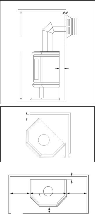
MODELS L20 BF-2 AND L20 DVF-2 CLEARANCES TO COMBUSTIBLE MATERIALS
These appliances can be installed in most residential room configurations, parallel to a rear or adjacent wall, or in an alcove that allows for the minimum clearances to combustible surfaces. Your local building inspector should review your plans prior to installation.
When installing this appliance, provide adequate clearances around air openings and adequate clearances for purposes of servicing and proper operation.
As determined through the safety certification of this unit, a minimum clearance to combustible materials must be maintained around specific areas of the gas appliance.
(Refer to Figures 1 through 3)
The clearances listed here are minimum distances and only apply in the configuration shown. Do not use clearances from one installation configuration with clearances from another to obtain closer clearances.
Top of appliance (min.) |
36” (inches) |
This includes any projections such as shelves, window sills, mantels, etc. above the appliance.
Back Wall |
2" (inches) |
Side Wall |
12" (inches) |
Corner (45° angle) |
2" (inches) |
stove corners to wall |
|
Ceiling Minimum |
65" (inches) from floor |
Alcove Min. Height |
65" (inches) from floor |
Alcove Min. Width |
47" (inches) |
Alcove Max. Depth |
24" (inches) from unit face. |
The stove can not be placed deeper into an alcove than 24” from the stove face to alcove opening.
Floor |
0 inches |
MANUFACTURED (MOBILE) HOME REQUIREMENTS
Model L20 DVF-2 may be installed in an aftermarket permanently located, manufactured home, where not prohibited by local codes. When installed in Manufactured Housing the following supplemental requirements must be met:
The appliance must be secured to the floor. Use the (3) ¼”-20x2 ¾” bolts (which secured appliance pedestal base to the wooden pallet) for securing appliance to the manufactured home floor.
The appliance must be grounded to the chassis of the manufactured home. Use a No. 8 or heavier copper wire at least 18" in length.
Model L20 BF-2 is NOT approved for Manufactured Home installations.
IMPORTANT NOTES:
The structural integrity of the manufactured home floor, walls, ceiling and roof must be maintained.
A manufactured (mobile) home installation must conform with the Manufactured Home Construction and Safety Standard, Title 24 CFR, Part 3280, or, when such a standard is not applicable, the Standard for Manufactured Home Installations, ANSI / NCSBCS A225.1, or standard for Gas equipped Recreational Vehicles and Mobile Housing, CSA Z240.4.
PAGE 6
Rear Wall or Alcove
65 Inch
(1651 mm) Min. Ceiling Height
2” Min. (51 mm)
Fig. 1
Corner
2” Min. (51 mm)
Fig. 2 |
|
2” Min. |
|
|
(51 mm) |
|
|
|
|
Rear Wall or Alcove |
|
|
|
2” Min. (51 mm) |
12” Min. |
Ref. 23” (584 mm) |
12” Min. |
(305 mm) |
(305 mm) |
|
Fig. 3 |
24” Max. (610 mm) |
|
|
|
|
FLOOR PROTECTION
When installed directly on carpeting, •tile or other combustible material other than wood flooring, the appliance shall be installed on a metal or wood panel extending the full width and depth of the appliance (see notes below).
• Notes:
1) Ceramic tile is non-combustible and does not require a wood or metal panel under the appliance. 2) Models with a pedestal base where base dimensions exceed width and depth of stove body, qualify as the floor protection
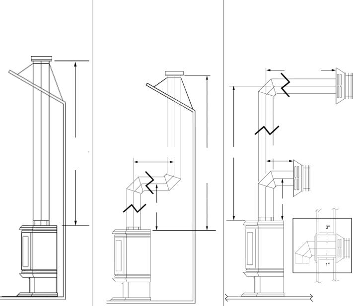
INSTALLATION - MODEL L20 DVF-2 (DIRECT-VENT) VENTING REQUIREMENTS.
This appliance is designed to be vented with a 4” x 6 5/8” direct-vent pipe. Each direct-vent appliance must use its own separate vent system.
VERTICAL TERMINATION WITH NO OFFSETS
Min. Vertical Pipe Length: 5 feet
Max. Vertical Pipe Length: 25 feet
5 Feet
Min.
25 Feet
Max.
VERTICAL TERMINATION WITH 2 OFFSETS
Min. Vertical Pipe From Appliance to first offset: 2 feet.
Min. Total Vertical Pipe Length: 5 feet
Max. Total Vertical Pipe Length: 25 feet
For every 1 feet of vertical pipe (from unit to first offset), 2 feet of horizontal run is allowed (not to exceed 12 ft.
Example – with a 6’ vertical pipe off unit, 12’ of horizontal run is allowed.
At 2’ Min. Vertical, 2’ Max.
Horizontal is allowed. 5 Feet Min.
25 Feet
Max.
* 2 Feet Min.
Horizontal runs require ¼” rise per foot.
HORIZONTAL TERMINATION WITH 1 OFFSET
Min. Vertical Pipe From Appliance to offset: 2 feet.
Max. Vertical Pipe Length: 25 feet
12 Feet Max.
|
|
For every 1 feet of vertical |
|
|
|
pipe (from unit to first offset), |
|
|
|
2 feet of horizontal run is |
|
|
|
allowed (not to exceed 12 ft. |
|
|
|
Example – with a 6’ ver- |
|
|
|
tical pipe off unit, 12’ of |
|
|
|
horizontal run is allowed. |
|
|
|
|
|
25 |
|
|
|
|
At 2’ Min. Vertical, 2’ Max. |
||
Feet |
|
Horizontal is allowed. |
|
Max. |
|
|
|
|
|
|
|
* 2 Feet Min.
Wall
Penetration
Detail
Maximum total offsets allowed: Not to exceed 180 degrees. Maximum allowable horizontal pipe run is 12 feet.
With 2 feet of vertical pipe installed from the appliance (* see note), a 2 foot maximum horizontal run allowed. For installations with more than 2 feet of vertical pipe, calculate allowable horizontal run as indicated in applicable illustration above.
See page 10 for Vent Termination Requirements.
Also see pipe manufacturers instructions for additional vent installation requirements. Horizontal vent clearances: 3“ minimum top 1“ minimum on bottom and sidewalls. Vertical vent clearances: 1” minimum.
Install vent support brackets every 4 feet of vertical pipe unless otherwise specified by vent manufacturer.
* Note: If using Propane Gas (LP), it may be necessary to install (as a minimum) 3 feet of vertical pipe from the appliance prior to an offset to ensure optimum product performance. This may be necessary due to variations in vent configuration and other numerous factors which affect exhaust flow and air delivery such as BTU value, ambient temperature, wind conditions, altitude, etc.
PAGE 7
INSTALLATION
DIRECT VENT SYSTEM COMPONENTS – MODEL L20 DVF-2 ONLY
The following Direct-Vent system components may be safely used model L20 DVF-2.
Model # |
Brand: SECURITY / Description |
Model # |
Brand: SIMPSON DURA-VENT / Description |
|
|
|
|
SV 0 SHK |
Standard Horizontal Term. Kit (90°Black Elbow, Firestop (2), Horizon- |
970 |
Basic Horizontal Term. Kit (90° Black Elbow, Wall Thimble Cover, |
|
tal Square Term. Cap) |
|
Horizontal Square Term. Cap) |
SV 0 HK |
Horizontal Term. Kit (90°Black Elbow, Firestop (2), Horizontal Term. |
971 |
Horizontal Term. Kit A (90°Black Elbow, Wall Thimble Cover, Hori- |
|
Cap, adj. Black length 1-1/2 – 6”) |
|
zontal Square Term. Cap, adj. 24” black pipe, 11-14 5/8” adj. Black |
|
|
|
pipe) |
SV 0 FK |
Vertical Flat Roof Term. Kit (w/flashing, storm collar, vertical Term. |
973 |
Vertical Termination Kit |
|
Cap) |
|
|
SV 0 FAK |
Vertical pitched Roof Kit, 1/12-7/12 (with adjustable roof flashing, |
978 |
Vertical Pitched Roof Kit, 0/12–6/12 (with adjustable flashing, storm |
|
storm collar, vertical termination cap) |
|
collar, low profile term. Cap) |
SV 0 FBK |
Vertical pitched Roof Kit, 8/12-12/12 (with adjustable roof flashing, |
N/A |
N/A |
|
storm collar, vertical termination cap) |
|
|
SV 0 L6 |
6” Pipe Length (Galvalume) |
|
6” Pipe Length (Galvalume) |
SV0 LB6 |
6” Pipe Length (Black) |
908B |
6” Pipe Length (Black) |
SV 0 |
9” Pipe Length ( Black) |
907B |
9” Pipe Length ( Black) |
SV 0 L12 |
12” Pipe Length (Galvalume) |
906 |
12” Pipe Length (Galvanized) |
SL 0 LB12 |
12” Pipe Length (Black) |
906B |
12” Pipe Length (Black) |
SV 0 L24 |
24” Pipe Length (Galvalume) |
904 |
24” Pipe Length (Galvanized) |
SV 0 LB24 |
24” Pipe Length (Black) |
904B |
24” Pipe Length (Black) |
SV 0 L36 |
36” Pipe Length (Galvalume) |
903 |
36” Pipe Length (Galvanized) |
SV 0 LB36 |
36” Pipe Length (Black) |
903B |
36” Pipe Length (Black) |
SV 0 L48 |
48” Pipe Length (Galvalume) |
902 |
48” Pipe Length (Galvanized) |
SV 0 LB48 |
48” Pipe Length (Black) |
902B |
48” Pipe Length (Black) |
N/A |
N/A |
911B |
11”-14” Adj. Pipe Length (Black) |
SV 0 LA |
1 ½- 6” Adj. Pipe Length |
N/A |
N/A |
SV 0 LBA |
1 ½- 6” Adj. Black Pipe Length |
N/A |
N/A |
SV 0 E45 |
45 Elbow (Galvalume) |
945 |
45 Elbow (Galvanized) |
SV 0 EB45 |
45 Elbow (Black) |
945B |
45 Elbow (Black) |
SV 0 E90 |
90 Elbow (Galvalume Swivel) |
990G |
90 Elbow (Galvanized Swivel) |
SV 0 EB90 |
90 Elbow (Black Swivel) |
990BG |
90 Elbow (Black Swivel) |
SV 0 |
90 Elbow (Galvalume) |
990 |
90 Elbow (Galvanized) |
SV 0 |
90 Elbow (Black) |
990B |
90 Elbow (Black) |
SV 0 CHC |
Horizontal Standard Term. Cap |
984 |
Horizontal Standard Term. Cap |
SV 0 CHCV |
Horizontal High Wind Term. Cap |
N/a |
Horizontal High Wind Term. Cap |
SV 0 CPB |
•Vertical Termination Cap |
983 |
•Vertical Termination Cap |
SV 0 CGV |
•Vertical High Wind Cap |
991 |
•Vertical High Wind Cap |
SV 0 STC36 |
Snorkel Termination Cap 36” |
981 |
Snorkel Termination Cap 36” |
SV 0 STC14 |
Snorkel Termination Cap 14” |
982 |
Snorkel Termination Cap 14” |
SV 0 |
Vinyl Shield Protector |
950 |
Vinyl Siding Standoff |
SV 0 VS |
RoundCeilingSupport |
940 |
RoundCeilingSupport |
|
/WallThimbleCover |
|
/WallThimbleCover |
SV 0 CSB |
Cathedral Ceiling Support Box, decorative square |
941 |
Cathedral Ceiling Support Box |
SV 0 SF |
BlackPlate,Decorative |
N/A |
N/A |
SV 0 |
RoundCeilingSupportBox/Wall |
942 |
RoundCeilingSupportBox/Wall |
|
Thimble |
|
Thimble |
SV 0 |
Storm Collar |
953 |
Storm Collar |
SV 0 RSM |
Wall Radiation Shield |
N/A |
N/A |
SV 0 BF |
Firestop |
N/A |
N/A |
N/A |
N/A |
963 |
Firestop Spacer |
SV 0 F |
Flashing, Flat Roof (storm collar included) |
|
|
SV 0 FA |
Flashing, Adjustable roof 1/12-7/12 (storm collar included) |
943 |
Flashing 0/12-6/12 |
SV 0 FB |
Flashing, Adjustable 8/12-12/12 (storm collar included) |
943S |
Flashing 7/12-12/12 |
SV 0 BM |
Wall Band |
988 |
Wall Strap |
|
|
|
|
Snorkel Caps: These are elongate vent termination caps, which incorporate the principles of natural draft into a horizontal installation. Two styles are common, 14” and 36” (Cap height). They enhance draft and relieve backpressure by creating natural draft in the snorkel.
Horizontal Caps: This 13 ½” square horizontal cap is placed on the outer wall of the dwelling. Not to be within 9” of an air inlet or within 12” of the ground. It requires a minimum 2’ rise on the interior pipe.
•Vertical Termination Cap: Low profile and high wind caps can only be used on vertical pipe installations.
PAGE 8
INSTALLATION - MODEL L20 DVF-2 ONLY
Direct Vent Retrofit Of Existing Chimney System - An existing Class-A (wood-burning) Metal Chimney or Masonry Chimney can be converted to a direct vent system. Use one of the following chimney conversion kits listed below. Have the existing chimney system inspected by a professional prior to the conversion. If using Simpson Dura-Vent brand liner kit, see “IMPORTANT” note at the top of page 8. The chimney conversion should not be applied to the portion of the vent system that is in the room of the appliance. Use only Co-Axial direct vent pipe (4” inner pipe, 6 5/8” outer pipe as listed on page 8) from the appliance to the retro-connector into converted flue system. Adhere to all specifications shown on pages 6 and 7 regarding clearances to combustibles, vertical and horizontal vent length minimums and maximums, etc. Read all instructions in this manual and provided by vent manufacturer with kit carefully before starting the installation. Failure to follow the instructions may create a fire or other safety hazard, and will void the warranty.
Model # |
Brand: SECURITY / Description |
Model # |
Brand: SIMPSON DURA-VENT / Description |
SV4MCK |
Masonry Chimney Conversion Kit –Vertical term. Cap, |
934 |
Masonry Chimney Conversion Kit |
|
cap adapter, masonry cover, black adapter (to flex), 2 |
|
|
|
gear clamps |
|
|
SV4CCK1 |
Factory Built Chimney Conversion Kit – for 6” I.D., 1” |
931 |
Factory Built Chimney Conversion Kit A – for 6” |
|
insulation. |
|
I.D.; Only compatible w/specific brands – Contact |
|
|
|
Vent Manufacturer |
SV4CCK2 |
Factory Built Chimney Conversion Kit – for 7” I.D., 1” |
932 |
Factory Built Chimney Conversion Kit B – for 6”, 7” |
|
insulation; 8” I.D., 1” insulation; 6” I.D., 2” insulation. |
|
& 8” I.D.; Only compatible w/specific brands – |
|
|
|
Contact Vent Manufacturer |
SV4CCK3 |
Factory Built Chimney Conversion Kit – for 10” I.D., 1” |
933 |
Factory Built Chimney Conversion Kit C – for 7” & |
|
insulation; 7” I.D., 2” insulation; 8” I.D., 2” insulation. |
|
8” I.D.; Only compatible w/specific brands – Con- |
|
|
|
tact Vent Manufacturer |
MODELS L20 BF-2 AND L20 DVF-2
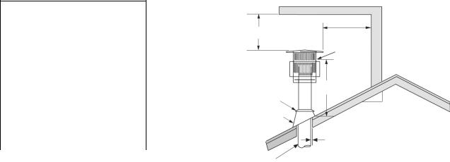
VERTICAL VENT TERMINATION REQUIREMENTS
These instructions should be used as a guideline and do not supersede local codes in any way. Install vent according to local codes, these instructions, the current National Fuel Gas Code (ANSI-Z223.1) in the USA or the current standards of CAN/CGA-B149.1 and - B149.2 in Canada.
Terminate multiple vent terminations according to the installation codes listed above.
Terminate single vent caps relative to building components according to the following chart & illustration. The vent/air intake termination clearances above the high side of an angled roof is as shown in the following chart:
Termination Heights For Vents
Above Flat or Sloped Roofs
Roof Pitch |
Feet |
Meters |
Flat to 6/12 |
1 |
0.3 |
6/12 to 7/12 |
1.25 |
0.38 |
7/12 to 8/12 |
1.5 |
0.46 |
8/12 to 9/12 |
2 |
0.61 |
9/12 to 10/12 |
2.5 |
0.76 |
10/12 to 11/12 |
3.25 |
0.99 |
11/12 to 12/12 |
4 |
1.22 |
12/12 to 14/12 |
5 |
1.52 |
14/12 to 16/12 |
6 |
1.83 |
16/12 to 18/12 |
7 |
2.13 |
18/12 to 20/12 |
7.5 |
2.29 |
20/12 to 21/12 |
8 |
2.44 |
•Venting terminals shall not be recessed into a wall or siding.
•Ref. NFPA 54 / ANSI Z223.1, 7.6, fig. 13: Gas Vent Termination locations for listed Caps, 12 inches or less in size, at least 8 feet from a vertical wall.
Horizontal Overhang
2 Ft. Min.
Vent
Termination
Storm
Collar
Flashing
Concentric
Vent Pipe
2 Ft. Min.
Lowest
Discharge
Opening
* H
X
12
Roof Pitch is X/12
1 inch (25.4 mm) Minimum Clearance to Combustibles
* H = Minimum height from roof to lowest discharge opening of vent.
PAGE 9
INSTALLATION - MODEL L20 DVF-2 ONLY
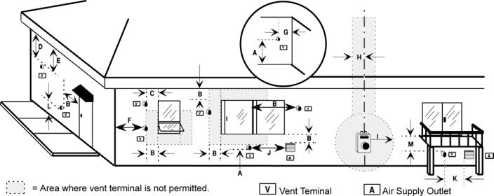
HORIZONTAL VENT TERMINATION REQUIREMENTS
The venting terminals should not be recessed into a wall or siding.
A = |
2” |
Clearances above grade, veranda, porch, deck or bal- |
|
|
|
cony. |
|
B = |
12” |
Clearance to window or door that may be opened. |
|
C = |
9” |
(USA) Clearance to permanently closed window. |
|
|
12” (CAN) |
|
|
D = |
24” |
Vertical clearance to ventilated soffit located above the |
|
|
|
terminal within a horizontal distance of 2 feet (60 cm) |
|
|
|
from the center-line of the terminal. |
|
E = |
12” |
Clearance to unventilated soffit. |
|
F = |
9” |
Clearance to outside corner. |
|
G = |
6” |
Clearance to inside corner. |
|
H = |
3 ft. (USA) |
Not to be installed above a meter/regulator |
|
|
|
assembly within 3 feet (90 cm) horizontally from the |
|
|
|
centerline of the regulator. |
|
I = |
3 ft. (USA) |
Clearance to service regulator vent outlet. |
|
|
6 ft.(CAN) |
|
|
J = 9” (USA) Clearance to non-mechanical air supply inlet to building or the combustion air inlet to 12“ (CAN) any other appliance.
K = 3 ft. (USA) Clearance to a mechanical air supply inlet. 6 ft. (CAN)
L* = 7 ft. (USA) Clearance above paved side-walk or a paved driveway located on public property.
M**= 12” Clearance under veranda, porch, deck or balcony
*A vent shall not terminate directly above a side-walk or paved driveway which is located between two single family dwellings and serves both dwellings.
**Only permitted if veranda, porch, deck or balcony is fully open on a minimum of 2 sides beneath the floor.
•Note: Local Codes or Regulations may require different clearances.
PAGE 10
 Loading...