


G A S F U R N A C E S
G43UF
MERIT® SERIES
Up−Flow
E N G I N E E R I N G D A T A
Bulletin No. 210394
August 2005
Supersedes December 2004
AFUE − up to 92.1%
Input − 44,000 to 132,000 Btuh
Nominal Add−on Cooling − 2 to 5 Tons
MODEL NUMBER IDENTIFICATION
G 43 UF − 24B − 045
Unit Type 
G = Gas Furnace
Series
43 = 90% Minimum AFUE
Configuration
UF = Up−Flow
Nominal Add−On Cooling Capacity
24 = 2 tons (7.0 kW)
36 = 3 tons (10.5 kW)
48 = 4 tons (14.10 kW)
60 = 5 tons (17.5 kW)
Nominal Gas Heat Input
045 = 44,000 Btuh (12.9 kW)
070 = 66,000 Btuh (19.3 kW)
090 = 88,000 Btuh (25.8 kW)
110 = 110,000 Btuh (32.2 kW)
135 = 132,000 Btuh (38.7 kW)
1 Cabinet Width
B = 17−1/2 in. (445 mm) C = 21 in. (533 mm)
D = 24−1/2 in. (622 mm)
1 Indoor coils with the same letter designation will physically match the furnace.
FEATURES
CONTENTS
Blower Data . . . . . . . . . . . . . . . . . . . . . . . . . . . . . . . . Pages 13−15 Dimensions . . . . . . . . . . . . . . . . . . . . . . . . . . . . . . . . . . Pages 9−12 Exhaust Pipe Venting Information . . . . . . . . . . . . . . . . . . . Page 7 Features and Options . . . . . . . . . . . . . . . . . . . . . . . . . . Pages 2−4 Filter Air Resistance . . . . . . . . . . . . . . . . . . . . . . . . . . . . . . Page 8 High Altitude Information . . . . . . . . . . . . . . . . . . . . . . . . . . Page 8 Installation Clearances . . . . . . . . . . . . . . . . . . . . . . . . . . . . Page 8 Model Number Identification . . . . . . . . . . . . . . . . . . . . . . . Page 1 Optional Accessories Selection table . . . . . . . . . . . . . . . . Page 6 Specifications . . . . . . . . . . . . . . . . . . . . . . . . . . . . . . . . . . . . Page 5
WARRANTY
Duralok Plus® Aluminized Steel Heat Exchanger − Twenty years limited warranty.
All other covered components − Five years limited warranty. Refer to Lennox Equipment Limited Warranty certificate included with equipment for details.
APPROVALS
Units certified by CSA International and ratings are certified by GAMA.
Units tested and rated according to US DOE test procedures and FTC labeling regulations.
Blower data from unit tests conducted in Lennox Laboratory air test chamber.
Approved by the California Energy Commission and meets California Seasonal Efficiency requirements and California Nitrogen Oxides (NOx) Standards.
ENERGY STAR® certified units are designed to use less energy, help save money on utility bills, and help protect the environment.
ISO 9001 Registered Manufacturing Quality System.
APPLICATIONS
Input capacities of 44,000, 66,000, 88,000, 110,000, and 132,000 Btuh (12.9, 19.3, 25.8, 32.2, and 38.7 kW).
Energy efficiency (AFUE) up to 92.1%.
Compact cabinet with either side or bottom return air entry. Lennox add-on indoor coils, high−efficiency air cleaners and humidifiers can easily be added to furnace.
Shipped factory assembled with all controls installed and wired. Each unit factory test operated to ensure proper operation.
DIRECT VENT / NON−DIRECT VENT
Furnace can be installed in either Direct Vent or Non−Direct applications. In Direct Vent applications, combustion air is supplied from outdoors and flue gases are discharged outdoors. In Non−Direct Vent applications, combustion air is supplied from indoors and flue gases are discharged outdoors.
OPTIONS
Termination Kits
Facilitates installation of combustion air intake pipe and flue exhaust pipe.
Refer to venting table in this bulletin to determine pipe size needed and proper termination kit required.
See Specifications table and dimension drawings.
Termination Kit − Concentric − Direct Vent Applications Only
1−1/2, 2, or 3 inch (38, 51, or 76 mm) kit contains concentric termination assembly, reducer bushing and 45 degree elbow. Kit requires single hole penetration of roof or wall for installation. Roof Termination Flashing Kit is available for use with 1−1/2 and 2 inch Kits.
CSA certified.
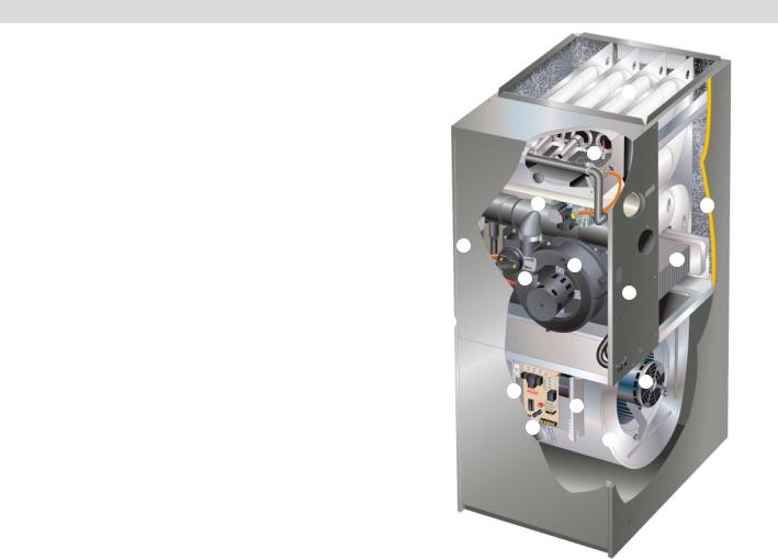
B
D
E N
K
G
F C
P
O
H |
|
L |
|
J |
|
|
|
|
|
I |
M |
|
|
Termination Kits − Wall Assembly
Close Couple − Direct Vent Applications Only
2 or 3 inch (51 or 76 mm) kit consists of close-couple, side-by-side PVC piping with galvanized steel wall cover plate for sealing and isolating piping penetration of the wall.
Piping spacing and length is sized for proper wall installations. CSA certified.
Close Couple WTK − Direct Vent Applications Only
2 or 3 inch (51 or 76 mm) kit contains one insulated faceplate, one insulated exhaust pipe, elbow and fittings.
Wall Ring − Direct or Non−Direct Vent
2 inch (51 mm) kit contains 2 stainless steel outside seal caps, 2 galvanized steel inside seal caps, 4 seal rings for the caps and 18 inch (457 mm) insulation sleeve for sealing and isolating intake and exhaust piping penetration of wall.
Maintain a maximum of 6 inches (152 mm) between the inlet and outlet openings in the installation of the pipes.
Roof Termination Flashing Kit − Direct or Non−Direct Vent
2 or 3 inch (51 or 76 mm) kit contains two neoprene rubber roof flashings for vertical venting through a roof.
Vent pipe and insulation not furnished. Each kit contains enough parts for two non−direct vent installations.
Also available for use with 1−1/2 inch (use 2 inch flashing) and 2 inch (use 3 inch flashing) Concentric Vent Termination Kits used in vertical venting rooftop applications.
G43UF / Page 2

FEATURES
B HEATING SYSTEM
Lennox Duralok Plus® Heat Exchanger Assembly
Lennox developed heat exchanger assembly consists of primary heat exchanger and secondary condenser coil assembly.
Main 3-pass clamshell type heat exchanger constructed of heavy−gauge, aluminized steel.
Designed for normal expansion and contraction.
Crimped seam design and construction provides maximum efficiency and minimum resistance to airflow.
C Secondary heat exchanger condenser coil constructed of aluminum fins fitted to stainless steel tubes.
Coil is factory tested for leaks.
Condensate drain header box assembly located on front of coil. Compact size of complete heat exchanger assembly permits low overall design of furnace cabinet.
All components mounted in a heavy−gauge steel frame.
Heat exchanger assembly has been laboratory life cycle tested.
Lennox Designed Header Box
Header box on end of condenser coil collects flue condensate for disposal through condensate collars.
Hose connects the header box drains to the condensate collars. The condensate collars are located on each side of the cabinet for easy field installation of condensate drain trap. Only one collar is used, the other is plugged.
Condensate drain trap is included with the unit for field installation.
Lennox Designed Flue Condensate Trap Assembly
Condensate trap assembly is mounted outside the conditioned air stream.
Assembly can be mounted on either side of cabinet. See Installation Instructions.
Connection can be made with field provided 1/2 in. PVC pipe, 3/4 in. PVC coupling, or 1−1/4 in. OD x 1 in. ID vinyl tubing with hose clamp. Easy to clean and winterize.
D Inshot Burners
Aluminized steel inshot burners provide efficient, trouble−free operation.
Burner venturi mixes air and gas in correct proportion for proper combustion.
Burner assembly is removable from the unit as a single component for ease of service.
Hot Surface Mini−Nitride Ignitor
Unique, non−porous, high strength proprietary ceramic material provides long life and trouble−free maintenance.
Low mass element provides fast heat−up and consistent igniter temperature with low power usage.
Cemented to alumina block for positive mounting and protection against current leakage.
High temperature Teflon® insulated ignition lead wires for dependable operation.
E Gas Control Valve
24 volt redundant combination gas control valve combines manual shut off valve (On−Off), automatic electric valve (dual) and gas pressure regulation into a compact combination control.
F Combustion Air Inducer
Shaded pole heavy−duty blower prepurges heat exchanger and safely vents flue products.
G Pressure switch proves blower operation before allowing gas valve to open.
Operates only during heating cycle.
Limit Control
Automatic reset, primary limit is accurately located. Factory installed on vestibule panel on all units.
Flame Rollout Switch
Manual reset switches are factory installed on burner box. Switch provides protection from abnormal operating conditions.
OPTIONS
High Altitude Orifice Kit − Natural Gas Only
Required for all natural gas models for proper unit operation at altitudes of 7501 to 10,000 feet (2286 to 3048 m).
Proper orifice for LPG/Propane models is included with LPG/Propane Conversion Kit.
High Altitude Pressure Switch Kit
Required on certain units for proper unit operation on installations above 4,500 ft. (1372 m).
LPG/Propane Conversion Kit
Required for field changeover from natural gas to LPG/Propane.
CONTROLS
H Integrated Furnace Control Board
Solid−state board contains all necessary controls and relays to operate furnace.
Combustion air inducer is controlled by board. Prior to ignition, a pre−purge cycle for 15 seconds is initiated. After the main burners are turned off, a post−purge cycle for 5 seconds is run. Ignition control board continuously monitors line voltage and maintains the igniter power at a constant level to provide consistent lighting and maximum igniter life.
Electronic flame sensor control assures safe and reliable operation. Should loss of flame occur, flame sensor controls will initiate 4 attempts at re−ignition before locking out unit operation for 60 minutes.
Watchguard type circuit automatically resets ignition controls after one hour of continuous thermostat demand after unit lockout, eliminating nuisance calls for service.
Fan control consists of adjustable blower timed−off delay (60, 90, 120, 180 seconds − factory setting 90 seconds) and fixed blower timed−on delay (45 seconds).
For air−conditioning applications, blower is automatically energized on thermostat demand for cooling.
I Two accessory terminals furnished for additional power supply requirements for 120 volt (less than 1 amp) power humidifiers and powered air cleaners.
Ignition control has two LED’s to indicate status and as an aid in troubleshooting.
J 24 Volt Transformer
Furnished and factory installed in control box. 40VA transformer has fuse wired in series.
K Field Wiring Make-up Box
Furnished for line voltage wiring.
Factory installed internally on left side of furnace.
Box may be installed internally or externally on either side of furnace.
OPTIONS
Thermostat
See Thermostat bulletins in Controls section and Lennox Price Book for a complete list of thermostats.
Twinning Kit
Required to operate two furnaces simultaneously. Kit consists of twinning control and two fan sensors.
BLOWER
L Multi-speed, direct drive blower. Statically and dynamically balanced. Resiliently mounted.
M Blower assembly slides out of unit for servicing.
Blower speeds are easily changed on the integrated furnace control board. See blower performance tables.
G43UF / Page 3

FEATURES
FILTER (NOT FURNISHED)
Filter and provisions for external mounting must be field provided.
OPTIONS
Air Filter and Rack Kit for Side Return Air Applications (Not for use with RAB Return Air Base)
Washable or vacuum cleanable polyurethane frame type filter and external side return air rack available for field installation. Available in single and ten pack kits.
Rack has filter door for easy filter servicing. Flanges on rack allow easy duct connection. Field installs on either side of unit cabinet.
See dimension drawing.
EZ Filter Base for Bottom Return Air Applications
Hinged door with thumbscrew for easy filter access. Uses standard size filters (field provided).
CABINET
Low−profile, narrow width cabinet allows easy installation. Heavy−gauge, cold rolled steel construction.
Pre−painted cabinet finish.
Flanges provided on supply air opening for ease of plenum connection or alignment with indoor coil.
N Cabinet is insulated with foil faced insulation on sides and back of heating compartment.
O Complete service access.
Safety interlock switch automatically shuts off power to unit when blower compartment access door is removed.
P Gas piping and electrical inlets are provided in both sides of cabinet.
Return Air Entry:
For bottom return−air entry, remove furnished bottom seal panel from cabinet.
For side return−air entry, corners are marked on either side of cabinet for return air cut−outs. On furnaces with side return air and condensate trap on the same side of the cabinet, a field fabricated transition or RAB is required to use an IAQ product higher than 14−3/16 in. (360 mm) when installed next to the unit and serviced from the front. IAQ products higher than 20 in. (508 mm) require a field fabricated transition. See dimension drawings.
NOTE − 60C and 60D size units that require air volumes over 1800 cfm (850 L/s) must have one of the following:
1.Single side return air with transition, to accommodate 20 x
25x 1 in. (508 x 635 x 25 mm) cleanable air filter, required to maintain proper air velocity.
2.Single side return air with optional RAB Return Air Base.
3.Bottom return air.
4.Return air from both sides.
5.Bottom and one side return air.
See Blower Performance Tables for additional information.
Coil Match−up
All furnaces exactly match C33 and CX34 cased up−flow indoor coils with same letter designation in model number. No adaptor required. Engaging holes furnished on cabinet for alignment.
C33 uncased coils match furnaces without any overhang but require an optional adaptor base or field fabricated transition to match furnace opening. See C33 coil bulletin for additional information.
OPTIONS
Condensate Drain Heat Cable Kits
Self-limiting wattage heat cable prevents condensate drain from freezing in unconditioned areas.
Available in 6, 24 or 50 ft. (1.8, 7.3, or 15.2 m) lengths. Heat Cable Tape:
66 ft. (20 m) length, 1/2 in. (13 mm) wide fiberglass. 60 ft. (18 m) length, 2 in. (51 mm) wide aluminum foil.
Condensate Trap Alternate Location Kit
Allows condensate drain to be installed on the opposite side of the furnace from the exhaust venting (up−flow applications only).
RAB Return Air Base
On furnaces with side return air and condensate trap on the same side of the cabinet, a field fabricated transition or RAB is required when installing an IAQ product higher than 14−3/16 in. (360 mm) when installed next to the unit and serviced from the front. IAQ products higher than 20 in. (508 mm) require a field fabricated transition.
Must be used for 60C and 60D models with air volumes over 1800 cfm (850 L/s) in up−flow applications when only one side return is required.
Cabinet is pre−painted steel to match the furnace. See Dimension Drawing.
G43UF / Page 4

SPECIFICATIONS
Gas |
Model No. |
G43UF |
G43UF |
G43UF |
G43UF |
G43UF |
||||||
Heating |
|
−24B−045 |
−24B−070 |
−36B−070 |
−36C−090 |
−36C−090H |
||||||
Performance |
|
|
|
|
|
|
|
|
|
|
Canada Only |
|
|
Input − Btuh (kW) |
44,000 (12.9) |
66,000 (19.3) |
|
66,000 (19.3) |
88,000 (25.8) |
88,000 (25.8) |
|||||
|
Output − Btuh (kW) |
40,300 (11.8) |
61,000 (17.9) |
|
62,000 (18.2) |
82,000 (24.0) |
81,000 (23.7) |
|||||
|
|
|
|
|
|
|
|
|
|
|
|
|
|
Temperature rise range − _F (_C) |
30 |
− 60 |
50 |
− 80 |
|
40 |
− 70 |
40 |
− 70 |
50 |
− 80 |
|
|
(18 |
− 36) |
(28 |
− 44) |
|
(22 |
− 39) |
(22 |
− 39) |
(28 |
− 44) |
|
|
|
|
|
|
|
|
|||||
|
1 AFUE |
92.1% |
90.0% |
|
92.1% |
92.1% |
90.0% |
|||||
|
High static (CSA) − in. w.g. (Pa) |
.50 (124) |
.50 (124) |
|
.50 (124) |
.50 (124) |
.50 (124) |
|||||
|
|
|
|
|
|
|
|
|
|
|
|
|
Connections |
Intake / Exhaust Pipe (PVC) |
2 |
/ 2 |
2 |
/ 2 |
|
2 |
/ 2 |
2 |
/ 2 |
2 |
/ 2 |
|
|
|
|
|
|
|
|
|
|
|
|
|
in. |
Condensate Drain Trap (PVC pipe) − i.d. |
1/2 |
1/2 |
|
1/2 |
1/2 |
1/2 |
|||||
|
|
|||||||||||
|
with field supplied (PVC coupling) − o.d. |
3/4 |
3/4 |
|
3/4 |
3/4 |
3/4 |
|||||
|
hose with hose clamp − i.d. x o.d. |
1−1/4 x 1 |
1−1/4 x 1 |
|
1−1/4 x 1 |
1−1/4 x 1 |
1−1/4 x 1 |
|||||
|
Gas pipe size IPS |
1/2 |
1/2 |
|
1/2 |
1/2 |
1/2 |
|||||
|
|
|
|
|
|
|
|
|||||
Indoor |
Wheel nominal diameter x width − in. |
10 x 7 |
10 x 7 |
|
10 x 8 |
10 x 8 |
10 x 8 |
|||||
Blower |
(mm) |
(254 x 178) |
(254 x 178) |
|
(254 x 203) |
(254 x 203) |
(254 x 203) |
|||||
|
Motor output − hp (W) |
1/5 (149) |
1/5 (149) |
|
1/3 (249) |
1/3 (249) |
1/3 (249) |
|||||
|
Tons (kW) of add−on cooling |
1.5 − 2 |
1.5 − 2 |
|
2 |
− 3 |
2 |
− 3 |
2 |
− 3 |
||
|
|
(5.3 |
− 7.0) |
(5.3 |
− 7.0) |
|
(8.8 − 10.5) |
(7.0 − 10.5) |
(7.0 − 10.5) |
|||
|
|
|
|
|
|
|
|
|
|
|
|
|
|
Air Volume Range − cfm (L/s) |
465 − 1125 |
425 − 1020 |
710 − 1640 |
730 − 1630 |
730 − 1630 |
||||||
|
|
(220 |
− 530) |
(200 |
− 480) |
(335 |
− 775) |
(345 |
− 770) |
(345 |
− 770) |
|
|
|
|
|
|
|
|
||||||
Shipping Data − lbs. (kg) − 1 package |
132 (60) |
141 (64) |
|
146 (66) |
162 (74) |
162 (74) |
||||||
|
|
|
|
|
|
|
|
|
|
|||
Electrical characteristics |
|
120 volts − 60 hertz − 1 phase (less than 12 amps) |
|
|||||||||
|
|
|
|
|
|
|
|
|
|
|
|
|
SPECIFICATIONS
Gas |
Model No. |
G43UF |
|
G43UF |
G43UF |
G43UF |
G43UF |
|||||
Heating |
|
−48C−090 |
|
−48C−110 |
−48C−110H |
−60C−110 |
−60D−135 |
|||||
Performance |
|
|
|
|
|
|
Canada Only |
|
|
|
|
|
|
Input − Btuh (kW) |
88,000 (25.8) |
|
110,000 (32.2) |
110,000 (32.2) |
110,000 (32.2) |
132,000 (38.7) |
|||||
|
Output − Btuh (kW) |
82,000 (24.0) |
|
103,000 (30.2) |
101,000 (29.6) |
103,000 (30.2) |
123,000 (36.0) |
|||||
|
|
|
|
|
|
|
|
|
|
|
|
|
|
Temperature rise range − _F (_C) |
40 |
− 70 |
|
45 |
− 75 |
50 |
− 80 |
40 |
− 70 |
45 |
− 75 |
|
|
(22 |
− 39) |
|
(27 |
− 45) |
(28 |
− 44) |
(22 |
− 39) |
(27 |
− 45) |
|
|
|
|
|
|
|
|
|||||
|
1 AFUE |
92.1% |
|
92.1% |
90.0% |
92.1% |
92.1% |
|||||
|
High static (CSA) − in. w.g. (Pa) |
.50 (124) |
|
.50 (124) |
.50 (124) |
.50 (124) |
.50 (124) |
|||||
|
|
|
|
|
|
|
|
|
|
|
|
|
Connections |
Intake / Exhaust Pipe (PVC) |
2 |
/ 2 |
|
2 |
/ 2 |
2 |
/ 2 |
2 |
/ 2 |
3 |
/ 3 |
in. |
Condensate Drain Trap (PVC pipe) − i.d. |
1/2 |
|
1/2 |
1/2 |
1/2 |
1/2 |
|||||
|
|
|||||||||||
|
with field supplied (PVC coupling) − o.d. |
3/4 |
|
3/4 |
3/4 |
3/4 |
3/4 |
|||||
|
hose with hose clamp − i.d. x o.d. |
1−1/4 x 1 |
|
1−1/4 x 1 |
1−1/4 x 1 |
1−1/4 x 1 |
1−1/4 x 1 |
|||||
|
Gas pipe size IPS |
1/2 |
|
1/2 |
1/2 |
1/2 |
1/2 |
|||||
|
|
|
|
|
|
|
|
|||||
Indoor |
Wheel nominal diameter x width − in. |
10 x 10 |
|
10 x 10 |
10 x 10 |
11−1/2 x 10 |
11−1/2 x 10 |
|||||
Blower |
(mm) |
(254 x 254) |
|
(254 x 254) |
(254 x 254) |
(292 x 229) |
(292 x 229) |
|||||
|
Motor output − hp (W) |
1/2 (373) |
|
1/2 (373) |
1/2 (373) |
1 (746) |
1 (746) |
|||||
|
Tons (kW) of add−on cooling |
3 |
− 4 |
|
3 |
− 4 |
3 |
− 4 |
4 |
− 5 |
4 |
− 5 |
|
|
(10.5 |
− 14.0) |
|
(10.5 |
− 14.0) |
(10.5 |
− 14.0) |
(14.0 |
− 17.5) |
(14.0 |
− 17.5) |
|
|
|
|
|
|
|
|
|
|
|||
|
Air Volume Range − cfm (L/s) |
950 − 2180 |
|
885 − 2160 |
885 − 2160 |
1470 |
− 2720 |
1440 |
− 2730 |
|||
|
|
(450 − 1030) |
|
(420 − 1020) |
(420 − 1020) |
(695 − 1285) |
(680 − 1290) |
|||||
|
|
|
|
|
|
|
||||||
Shipping Data − lbs. (kg) − 1 package |
168 (76) |
|
178 (81) |
178 (81) |
186 (84) |
203 (92) |
||||||
|
|
|
|
|
|
|
|
|
||||
Electrical characteristics |
|
|
120 volts − 60 hertz − 1 phase (less than 12 amps) |
|
||||||||
|
|
|
|
|
|
|
|
|
|
|
|
|
NOTE − Filters and provisions for mounting are not furnished and must be field provided.
1 Annual Fuel Utilization Efficiency based on DOE test procedures and according to FTC labeling regulations. Isolated combustion system rating for non−weatherized furnaces
G43UF / Page 5
 Loading...