


Lennox E36ODGPE, E36ODGNE, E42ODGPE-H, E36ODGPE-H, E42ODGPE User Manual
...INSTALLATION
INSTRUCTIONS
|
|
|
|
|
|
|
|
|
|
OUTDOOR GAS FIREPLACE |
|
||
|
|
|
|
|
|
|
|
|
|
ELITE® SERIES |
|||
|
|
|
|
|
|
|
|
|
|
Outdoor GAS FIREPLACE |
|
|
|
|
|
|
|
|
|
|
|
|
|
P/N 850,034M REV. D 04/2009 |
|
|
|
|
This appliance is only for use with the type of gas |
|
|
|
|
|
|||||||
|
|
|
|
|
|
|
|||||||
|
indicated on the rating plate. This appliance is |
|
|
MODELS |
|
|
|
||||||
|
not convertible for use with other gases, unless a |
|
|
|
|
|
|
||||||
|
certified kit is used. |
|
|
|
|
|
E36ODGNE |
E42ODGNE |
|||||
|
|
|
|
|
|
|
|
|
|
E36ODGNE-H |
E42ODGNE-H |
||
|
|
|
|
|
|
|
|
|
|
||||
INSTALLER: Leave this manual with the appliance. |
|
|
E36ODGPE |
E42ODGPE |
|||||||||
|
|
E36ODGPE-H |
E42ODGPE-H |
||||||||||
CONSUMER: Retain this manual for future reference. |
|
|
|||||||||||
|
|
|
|
|
|
|
|
|
|
|
|||
|
|
|
|
|
|
|
|
|
|||||
INstallateur: Laissez cette notice avec l'appareil. |
|
|
A French manual is available upon request. Order Form Number |
||||||||||
CONsommateur: Conservez cette notice pour consula- |
|
|
850,034CF. |
|
|
|
|||||||
tion ultérieure. |
|
|
|
|
|
Ce manuel d’installation est disponible en francais, simplement en |
|||||||
|
|
|
|
|
|
|
|
|
|
||||
|
|
|
|
|
|
|
|
|
|
faire la demande. Numéro de la pièce 850,034CF. |
|||
|
|
|
|
|
|
|
|
|
|
||||
|
Warning:Iftheinformationinthismanual |
|
|
|
|
|
|
|
|
||||
|
|
|
|
|
|
|
|
|
|||||
|
|
|
|
AVERTISSEMENT: ASSUREZ-VOUS DE BIEN SUIVRE |
|
|
|||||||
|
is not followed exactly, a fire or explo- |
|
|
|
|
|
|||||||
|
sion may result causing property dam- |
|
|
|
LES INSTRUCTIONS DONNÉES DANS CETTE NOTICE |
|
|
||||||
|
age, personal injury or loss of life. |
|
|
|
POUR RÉDUIRE AU MINIMUM LE RISQUE D’INCENDIE |
|
|
||||||
|
|
|
|
|
|
|
|
|
D’EXPLOSION OU POUR ÉVITER TOUT DOMMAGE MA- |
|
|
||
Do not store or use gasoline or other flammable |
|
||||||||||||
|
|
TÉRIEL, TOUTE BLESSURE OU LA MORT. |
|
|
|||||||||
vapors or liquids in the vicinity of this or any |
|
|
|
|
|
|
|
||||||
|
|
Ne pas entreposer ni utiliser d’essence ni d’autre |
|
||||||||||
other appliance. |
|
|
|
|
|
||||||||
What to do if you smell gas: |
|
|
vapeurs ou liquides inflammables dans le voisinage |
|
|||||||||
|
|
de cet appareil ou de tout autre appareil. |
|
||||||||||
• |
DO NOT light any appliance. |
|
|
Que faire si vous sentez une odeur de gaz: |
|
||||||||
• |
DO NOT touch any electrical switches, do not |
|
|
|
|||||||||
|
|
|
|
|
|
|
|||||||
|
|
use any phone in your building. |
|
|
• Ne pas tenter d’allumer d’appareil. |
|
|||||||
• Immediately call your gas supplier from a |
|
|
• |
Ne touchez à aucun interrupteur. Ne pas vous servir |
|
||||||||
|
|
neighbor’s phone. Follow your gas suppliers |
|
|
|
des téléphones se trouvant dans le bátiment où |
|
||||||
• |
instructions. |
|
|
|
|
|
vous vous trouvez. |
|
|
|
|||
If your gas supplier cannot be reached, call |
|
|
• |
Appelez immédiatement votre fournisseur de gaz |
|
||||||||
|
|
the fire department. |
|
|
|
|
|
||||||
|
|
|
|
|
|
|
depuis un voisin. Suivez les instructions du fournis- |
|
|||||
|
|
|
|
|
|
|
|
|
|
|
|||
Installation and service must be performed by |
|
|
|
seur. |
|
|
|
||||||
|
|
• Si vous ne pouvez rejoindre le fournisseur de gaz, |
|
||||||||||
a qualified installer, service agency or the gas |
|
|
|
||||||||||
|
|
|
appelez le service des incendies. |
|
|||||||||
supplier. |
|
|
|
|
|
|
|||||||
|
|
|
|
|
|
|
|
|
|||||
|
|
|
|
|
|
|
|
|
L’installation et l’entretien doivent être assurés par |
|
|||
|
|
|
|
|
|
|
|
|
|
||||
|
|
|
|
Portland |
|
|
|
|
un installeur ou un service d’entretien qualifié ou par |
|
|||
|
|
OTL Report No. 116-F-41-5 |
|
||||||||||
|
|
|
|
|
|
|
le fournisseur de gaz. |
|
|
|
|||
|
|
|
US |
|
|
|
|
|
|
|
|||
|
|
|
|
|
|
|
|||||||
|
|
|
|
|
NOTE: DIAGRAMS & |
ILLUSTRATIONS NOT TO SCALE. |
|
|
|||||
|
|
|
|
|
|
|
|
|
|||||
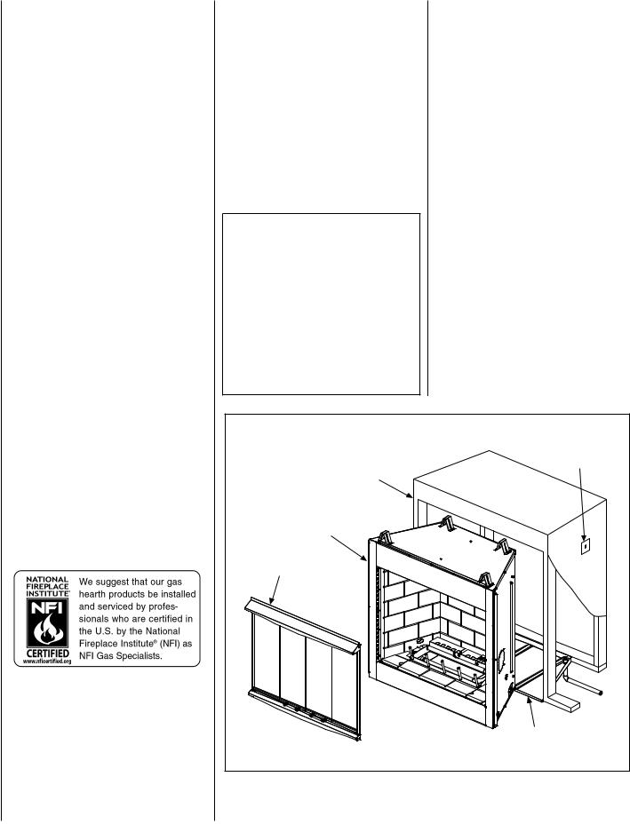
TABLE OF CONTENTS |
|
|
Packaging.......................................... |
page |
2 |
Introduction....................................... |
page |
2 |
New York & Massachusetts |
|
|
Requirements................................ |
page |
3 |
General Information........................... |
page |
3 |
Location............................................. |
page |
4 |
Waterproofing The Fireplace ............. |
page |
5 |
Appliance Clearances......................... |
page |
5 |
Clearance Specifications.................... |
page |
6 |
Fireplace Installation.......................... |
page |
7 |
Routing Gas Line............................... |
page |
7 |
Fireplace Specifications..................... |
page |
8 |
Framing Specifications...................... |
page |
9 |
Field Wiring....................................... |
page |
10 |
Connecting Gas Line ......................... |
page |
11 |
Installing The Logs............................ |
page |
12 |
Checking Appliance Operation........... |
page |
13 |
Firebox Finishes................................. |
page |
13 |
Accessories And Components........... |
page |
14 |
Gas Conversion Kits................... |
page 15 |
|
This installation manual will help you obtain a safe, efficient, dependable installation for your appliance.
This manual is part of a set of two supporting this product. Refer to manual 875,032M for
Care And Operations.
Please read and understand these instructions before beginning your installation.
PACKAGING
The assembled outdoor gas fireplace is packaged with the following:
1 - the logs are packaged in a carton located within the firebox.
2- one envelope containing the literature package which consists of the Homeowner's manual, Installation Instructions and Warranty.
3- three (3) bags of lave rock, envelope is located in the firebox area.
4- Electrical kit containing the wall switch components, battery holder, box and cover (see Field Wiring page 10).
Introduction
These outdoor gas fireplaces are designed for exterior applications. These appliances must be installed outdoors.
The Lennox Elite® Series Outdoor Gas Fireplace is designed for outdoor use. It may also be installed in screened porches and lanais that meet these minimum requirements:
Minimum porch area - 96 square feet Minimum ceiling height - 7 feet 8 inches
A minimum of two (2) walls can be screened but must be open to outside ventilation. Minimum screen area - 64 square feet Minimum screen top height - 6 feet 8 inches
Refer to Clearance Specifications on Page 6.
Electronic appliances are designed to operate on natural gas or propane. An electronic intermittent pilot ignition system provides safe, efficient operation. A battery pack is required to operate these units.
These appliances comply with National Safety Standards and are tested by Omni Test Laboratories (Report No. 116-F-41-5) and listed by CSA-4-96 in both USA and Canada, as outdoor gas fireplaces.
The Installation must conform to local codes or, in the absence of local codes, with the National Fuel Gas Code, ANSI Z223.1/NFPA 54, or the Natural Gas and Propane Installation Code, CSA B149.1.
The appliance, when installed, must be electricallygroundedinaccordancewithlocalcodesor, in the absence of local codes, with the National Electrical Code, ANSI/NFPA 70, or the Canadian Electrical Code, CSA C22.1.
Do not attempt to alter or modify the construction of the appliance or its components. Any modification or alteration may void the warranty, certification and Listings of this unit.
TYPICAL INSTALLATION |
|
Weatherproof |
Wall Switch |
Enclosure |
|
Fireplace |
|
Accessories |
|
|
Optional drain Pan |
Figure 1 |
|
NOTE: DIAGRAMS & ILLUSTRATIONS NOT TO SCALE.

New York and Massachusetts requirements
These appliances may be installed in the following USA locations with the following requirements:
Installation of these appliances are approved for installation in the US state of Massachusetts if the following additional requirements are met -
•Installation and repair must be done by a plumber or gas fitter licensed in the Commonwealth of Massachusetts.
•The flexible gas line connectors shall not exceed 36 inches (92 centimeters) in length.
•The individual manual shut-off must be a t-handle type valve.
General Information
Note: Installation and repair should be performed by a qualified service person. The appliance should be inspected annually by a qualified professional service technician. More frequent inspections and cleanings may be required due to yard care, insects, etc. It is imperative that the control compartment and burners of the appliance be kept clean.
Provide adequate clearances around air openings and adequate accessibility clearance for service and proper operation. Never obstruct the front openings of the appliance.
These appliances are designed to operate on natural or propane gas only.
All Models -
All models have a manually modulated gas valve. Input is shown in Table 1:
Models with Manually-Modulated Gas Valve
Natural Gas |
Propane Gas |
||
|
Input |
|
Input |
Model No. |
rate |
Model No. |
rate |
|
(Btu/H) |
|
(Btu/H) |
|
50,000 |
|
46,000 |
E36ODG |
to |
E36ODG |
to |
|
39,500 |
|
37,000 |
|
50,000 |
|
46,000 |
E42ODG |
to |
E42ODG |
to |
|
39,500 |
|
37,000 |
Table 1
Gas Pressure - All Models
Tables 2 and 3 show the appliances' inlet and manifold gas pressure.
Inlet Gas Supply Pressure
(all models)
Fuel # |
Minimum |
Maximum |
|
Natural Gas |
5.0" WC |
10.5" WC |
|
(1.24 kPa) |
(2.61 kPa) |
||
|
|||
|
|
|
|
Propane |
11.0" WC |
13.0" WC |
|
(2.74 kPa) |
(3.23 kPa) |
||
|
|||
|
|
|
Table 2
Manifold Gas Supply Pressure
(all models)
Fuel # |
Low |
High |
|
Natural Gas |
(Lo) 2.2" WC |
(Hi) 3.5" WC |
|
(.55 kPa) |
(.87 kPa) |
||
|
|||
|
|
|
|
Propane |
(Lo) 6.3" WC |
(Hi) 10.0" WC |
|
(1.57 kPa) |
(2.49 kPa) |
||
|
|||
|
|
|
Table 3
Test gage connections are provided on the front of the gas control valve identified IN for the inlet and OUT for the manifold side. A 1/8" NPT Test gauge connection is provided at the inlet and outlet side of the electronic gas control valve.
These appliances must be isolated from the gas supply piping system (by closing their individual manual shut-off valve) during any pressure testing of the gas supply piping system at test pressures equal to or less than 1/2 psig (3.5 kPa).
These appliances and their individual shut-off valves must be disconnected from the gas supply piping system during any pressure testing of that system at pressures greater than 1/2 psig (3.5 kPa).
NOTE: DIAGRAMS & ILLUSTRATIONS NOT TO SCALE.
Orifice Sizes - Sea Level To High Altitude
(All Models)
These appliances are tested and approved for installation at elevations of 0-4500 feet (0-1372 meters) above sea level, using the standard burner orifice (See Table 4 ). For elevations above 4500 feet, contact your gas supplier or qualified service technician. Install the appliance according to the regulations of the local authorities having jurisdiction and, in the USA, the National Fuel Gas Code NFPA 54 / ANSI Z223.1 - latest edition or , in Canada, the CAN1B149.1 and .2 codes - latest edition.
Model |
Orifice size |
Elevation |
||
Natural |
|
Feet |
||
No. |
Propane |
|||
|
Gas |
(meters) |
||
E36OdG |
0.1405" |
0.0785" |
|
|
(#28) |
(#47) |
0-4500 |
||
|
||||
|
|
|
||
E42OdG |
0.1405" |
0.0785" |
(0-1372) |
|
(#28) |
(#47) |
|
||
|
|
|||
|
|
|
|
|
Table 4
Warning: Propane tanks are at pressures that will cause damage to valve components. Verify that the tanks have step down regulators to reduce the pressure to safe levels.
Assembly outline
Before You Start
Check your inventory list to be sure you have all the necessary parts supplied in good usable condition. Check also for any concealed damage.
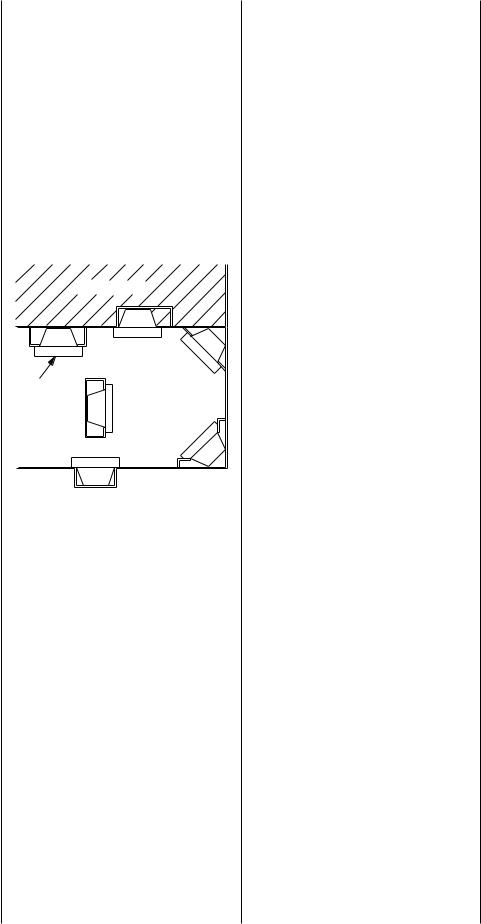
Location of fireplace
Carefully select the proper location for any obstructions, clearance to side wall(s), air availability, location and aesthetics. With proper pre-planning, a slight adjustment of a few inches can save considerable time and expense later during construction and assembly. See Figure 2 for some examples.
LIVING SPACE
Optional
Hearth PAtIO
Extension
Figure 2
When choosing a location, care must be taken to avoid places where flooding or running water may be a problem.
Identify the desired location for the battery pack/ON/OFF switch junction box location. This should be easily accessible and convenient for use and high enough on the wall to be protected from water and drifted snow.
Do not use these appliances if any part of the gas supply, control or burner has been submerged under water. Immediately call a qualified, professional service technician to inspect the appliance and to replace any parts of the control system and any gas control which have been under water.
Carefully consider the position of the fireplace opening with respect to the location of adjacent or nearby stairwells, doors, windows, walkways and over hanging trees, patios and wires.
When locating the fireplace, consideration must be given to combustibles and final finishing. See Figure 18 and confine the final location of combustible finish materials to the "Safe Zone". Also refer to Clearance Specifications on page 6.
Consider the effects of heat when locating any object in front of or near the fireplace opening.
Pre-installation notes
The fireplace may be installed directly on a combustible floor or raised on a platform of an appropriate height. Do not place the fireplace on vinyl or other soft floor coverings. It may, however, be placed on flat wood, plywood, particle board or other hard surfaces.
Position the electrical junction box as detailed in LOCATION OF FIREPLACE. (The umbilical cord is 9 feet long).
Be sure the fireplace rests on a solid continuous floor or platform with appropriate framing for support.
The fireplace may be positioned and then the framing built around it, or the framing may be constructed and the fireplace positioned into the opening.
Usually, no special floor support is needed for the fireplace, however, to be certain:
1.Estimate the total weight of the fireplace system including surround materials such as brick, stone, etc., to be installed. Shipping weights for the fireplace may be found on page 8.
2.Measure the square footage of the floor space to be occupied by the system, surrounds and hearth extensions.
3.Note the decking construction, i.e. 2 x 6’s,
2x 8’s or 2 x 10’s, single or double joists, type and thickness of floor boards.
4.Use this information and consult your local building code to determine if you need additional support.
If you plan to raise the fireplace and hearth extension, build the platform assembly then position fireplace and hearth extension on top. Secure the platform to the floor to prevent possible shifting.
NOTE: DIAGRAMS & ILLUSTRATIONS NOT TO SCALE.
Assembly steps
Note: The following steps represent the normal sequence of installation. Each installation is unique, however, and might require a different sequence.
1.Position firebox prior to framing or into prepared framing (non-combustible framing is recommended).
2.Position the electrical junction box as detailed in LOCATION OF FIREPLACE.
(The umbilical cord is 9 feet long).
3.Waterproof the fireplace or install the optional drip pan (see Waterproofing The Fireplace and
Figure 3 on page 5 ).
4.Plumb gas line. (Gas connections should only be performed by an experienced, licensed/certified tradesman.)
5.Complete the installation, finish wall material, surround and hearth extension to your individual taste.
6.Assemble and attach optional accessories.
Study the three dimensional illustration (Figure 1 ) to get a general idea of each element of your fireplace system.
Waterproofing the fireplace
Although the fireplace is designed to operate safely outdoors, rain may enter the hearth area, condensation and can cause water to collect inside the fireplace bottom.
To prevent water collection, the builder must provide a means to drain water from under the fireplace by building or installing a water collector of the builders choice, before positioning the fireplace in its location.
Special care must be taken when the fireplace is installed against an exterior wall. The enclosure surrounding the fireplace on the sides and back must be treated as an exterior wall.
Lennox does provide an optional drain pan to assist weatherproofing the fireplace.
H4651 DPSS36 Drain Pan for E36ODG, H4652 DPSS42 Drain Pan for E42ODG.

When Planning for the installation of the fireplace, the framing height must be increased from 46-1/2 inches to 47-1/4 inches, when installing the drain pan. An additional space below the fireplace will also be required to plumb a drain line.
Step 1. Seal all joints, gaps and corners around the bottom of the drain pan before positioning the fireplace on its location (Figure 3 ).
Step 2. On the exposed drain hole, install a PVC threaded coupling reducer, 3/4" x 1/2" going from the top of the pan down through the hole. Apply a silicone-based sealant around the base and threads before installation.
Step 3. Holding the reducer coupling with a wrench, thread a 3/4", 90 degree, PVC elbow to the reducer until it is tight to the metal.
Step 4. Add additional piping to route the drain to an appropriate location.
Note: To assure proper drainage, the fireplace must be installed on a leveled surface.
Clearances
Minimum clearance to combustibles for the fireplace is as follows; sides and back – 1/2" (13mm), combustible floor – 0" (0mm), adjacent wall 6" (152mm), ceiling – 50" (1270mm).
Refer to Figure 4 on this page and Figure 18 on page 13 for more detail.
Note: Clearance behind the nailing flange for both fireplace models is 1/2" (13mm).
Note: Adjacent wall considerations are for an adjacent wall to only a single side. Walls should not be placed at the minimum distance on both sides of the fireplace. Allow at least 4 feet on one side of the fireplace.
threaded |
threaded |
|
reducer |
||
Elbow 3/4 |
||
3/4 x /2 |
||
@ 90° |
||
(PVC) |
||
|
(PVC) |
|
drain Connector detail |
||
47 /4 |
|
|
Figure 3 |
|
|
|
|
Combustable Materials |
|
|
|
Allowed Flush With |
/2” Airspace Clearance |
|
|
the Face Front |
|
|
|
to Sides And Back |
|
/2” Airspace Clearance |
|
|
|
|
|
|
|
to Sides And Back |
|
|
/2” Clearance |
|
|
|
|
|
|
|
Nailing Flange May |
|
|
|
Make direct Contact |
|
|
|
With Combustible |
|
|
|
Framing |
No Material Within |
|
|
|
the Face Opening |
Noncombustable |
No Combustables |
|
Noncombustables |
|
Below the top Spacers |
|
|
Material Only |
||
|
|
||
May Overlap the Face |
tOP VIEW |
|
|
|
|
||
|
|
5” |
|
|
|
Only |
/2” |
|
|
Noncombustable |
|
|
|
Airspace |
|
|
|
Material May |
|
|
|
Clearance |
|
|
|
Overlap the |
|
|
|
to Back |
|
|
|
top Face |
|
|
|
|
|
|
|
do NOt Overlap |
|
|
|
Material Within |
|
|
|
the Face Opening |
|
|
|
No Material |
|
|
|
Allowed in |
|
|
|
this Area |
|
|
|
Combustible Material |
|
|
|
May Overlap the |
|
|
|
Face Bottom up to 2” |
|
Figure 4 |
|
Below the Face Opening |
SIdE VIEW |
|
|
|
|
NOTE: DIAGRAMS & ILLUSTRATIONS NOT TO SCALE.
 Loading...