


INSTALLATION AND MAINTENANCE
INSTRUCTIONS
2SCU13 Series
Split System Air Conditioner
 WARNING
The equipment covered in this manual is to be installed by trained and experienced service and installation technicians. Improper installation, modification, service, or use can cause electrical shock, fire, explosion, or other conditions which may cause personal injury, death, or property damage. Use appropriate safety gear including safety glasses and gloves when installing this equipment.

 WARNING
Risk of electrical shock. Disconnect all remote power supplies before installing or servicing any portion of the system. Failure to disconnect power supplies can result in property damage, personal injury, or death.

 WARNING
Installation and servicing of air conditioning equipment can be hazardous due to internal refrigerant pressure and live electrical components. Only trained and qualified service personnel should install or service this equipment. Installation and service performed by unqualified persons can result in property damage, personal injury, or death.

 WARNING
Sharp metal edges can cause injury. When installing the unit, use care to avoid sharp edges.
TABLE OF CONTENTS |
|
INSTALLATION ...................................... |
2 |
START-UP ............................................ |
10 |
OPERATION ........................................ |
14 |
MAINTENANCE ................................... |
14 |
CONNECTION DIAGRAMS ................. |
16 |
WARRANTY ......................................... |
18 |
Manufactured By
A.A.C.
A Lennox International Inc. Company
421 Monroe Street
Bellevue, OH 44811
*48283B006*
Save these instructions for future reference
# 48283B006 |
Page 1 |
INSTALLATION
General
Read this entire instruction manual, as well as the instructions supplied in separate equipment, before starting the installation. Observe and follow all warnings, cautions, instructional labels, and tags. Failure to comply with these instructions could result in an unsafe condition and/or premature component failure.
These instructions are intended as a general guide only for use by qualified personnel and do not supersede any national or local codes in any way. The installation must comply with all provincial, state, and local codes as well as the National Electrical Code (U.S.) or Canadian Electrical Code (Canada). Compliance should be determined prior to installation.
When servicing or repairing HVAC components, ensure the fasteners are appropriately tightened. Table 1 shows torque values for fasteners.
Torque Table
Fastener |
Torque |
|
|
Stem Caps |
8 ft. lbs. |
|
|
Service Port Caps |
8 ft. lbs. |
Sheet Metal Screws |
16 in. lbs. |
|
|
#8 Machine Screws |
16 in. lbs. |
#10 Machine Screws |
28 in. lbs. |
|
|
Compressor Bolts |
90 in. lbs. |
|
|
Table 1
Inspection of Shipment
Upon receipt of equipment, carefully inspect it for possible shipping damage. If damage is found, it should be noted on the carrier’s freight bill. Take special care to examine the unit inside the carton if the carton is damaged. Any concealed damage discovered should be reported to the last carrier immediately, preferably in writing, and should include a request for inspection by the carrier’s agent.
If any damages are discovered and reported to the carrier DO NOT INSTALL THE UNIT, as claim may be denied.
Check the unit rating plate to confirm specifications are as ordered.
Location of Unit
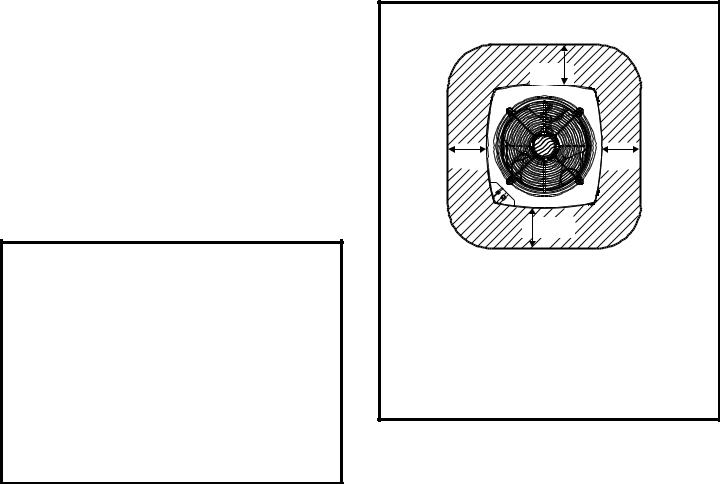
Outdoor units operate under a wide range of weather conditions; therefore, multiple factors must be considered when positioning the unit. The unit must be positioned to give adequate clearances for sufficient airflow and servicing. Refer to Figure 1 for installation clearances.
Installation Clearances
36
36 * |
36 |
36 *
*A service clearance of 30" must be maintained on one of the sides adjacent to the control box. Clearance to one of the other three sides must be 36". Clearance to one of the remaining two sides may be 12" and the final side may be 6".
A clearance of 24" must be maintained between units.
48" clearance required on top of unit. Maximum soffit overhang is 36".
Figure 1
Slab Mounting
When installing unit at grade level, install on slab high enough above grade to allow adequate drainage of water (see Figure 2). Top of slab should be located so runoff water from higher ground will not collect around unit. Refer to roof mounting section for barrier construction if unit must face prevailing winter winds.
Roof Mounting
Install unit at a minimum of 4" above surface of the roof. Care must be taken to ensure weight of unit is properly distributed over roof joists and rafters. Either redwood or steel supports are recommended.
If unit coil cannot be mounted away from prevailing winter winds, a wind barrier should be constructed (see Figure 3). Size barrier at least the same height and width as the outdoor unit. Mount barrier 24" from the sides of the unit in the direction of the prevailing winds.
Page 2 |
# 48283B006 |

Slab Mounting
Discharge Air
Building
Structure
Mounting Slab
Ground Level
2° or 2" per 5' slope tolerance away from building structure.
Figure 2
Wind Barrier Construction
Prevailing Winter Winds
Wind Barrier
Inlet Air
24"

 Inlet Air
Inlet Air
Figure 3
Electrical Wiring
All field wiring must be done in accordance with the National Electrical Code (NEC) recommendations, Canadian Electrical Code (CEC) and CSA Standards, or local codes, where applicable.

 WARNING
Unit must be grounded in accordance with national and local codes. Failure to ground unit properly can result in personal injury or death.
Refer to the furnace or blower coil Installation Instructions for additional wiring application diagrams and refer to unit rating plate for minimum circuit ampacity and maximum overcurrent protection size.
# 48283B006
1.Install line voltage power supply to unit from a properly sized disconnect switch. Any excess high voltage field wiring should be trimmed or secured away from the low voltage field wiring.
2.Ground unit at unit disconnect switch or to an earth ground. To facilitate conduit, a hole is in the bottom of the control box. Connect conduit to the control box using a proper conduit fitting. Units are approved for use only with copper conductors. 24V Class II circuit connections are made to the low voltage pigtails. A complete unit wiring diagram is located inside the unit control box cover (see also pages 16 and 17 of this instruction).
3.Install room thermostat on an inside wall that is not subject to drafts, direct sunshine, or other heat sources.
4.Install low voltage wiring from outdoor to indoor unit and from thermostat to indoor unit (see Figure 4).
5.Do not bundle any excess 24V control wire inside control box. Run control wire through installed wire tie and tighten wire tie to provide low voltage strain relief and to maintain separation of field-installed low and high voltage circuits.
Thermostat Designations
Thermostat |
Indoor Unit |
|
|
R |
Power |
R |
Outdoor |
|
Unit |
||
|
Heat |
|
|
W1 |
W |
|
|
|
|
||
Y |
Cooling |
Y |
Y1 Outdoor Unit |
|
|
||
G |
Indoor Blower |
|
|
|
G |
|
|
C |
|
C |
C Outdoor Unit |
|
|
||
See unit wiring diagram for power supply connections. If the indoor unit is not equipped with a blower relay, one must be field supplied and installed.
Do not connect C (common) connection between indoor unit and thermostat except when required by the indoor thermostat. Refer to thermostat installation instructions. C (common) connection between indoor unit and outdoor unit required for proper operation.
Figure 4
Refrigerant Piping
Field refrigerant piping consists of liquid and suction lines from the outdoor unit (sweat connections) to the indoor coil (flare or sweat connections).
Select line set diameters from Table 2 on page 4 to ensure that oil returns to the compressor. Size vertical
Page 3

suction riser to maintain minimum velocity at minimum capacity. Recommended line length is 50' or less. If more than 50' line set is required, contact Technical Services at (419) 483-4840.
Table 2 shows the diameters for line sets up to 100' although vertical lift applications and trapping requirements need to be reviewed with Technical Services for line sets over 50'.
Refrigerant Line Set Diameters (in.)
Liquid Line
BTUH |
Line Set Length and Size |
|
||||
|
|
|
|
|
|
|
12 ft. |
25 ft. |
50 ft. |
75 ft. |
100 ft. |
|
|
|
|
|||||
18,000 |
3/8 |
3/8 |
3/8 |
3/8 |
3/8 |
|
|
|
|
|
|
|
|
24,000 |
3/8 |
3/8 |
3/8 |
3/8 |
3/8 |
|
30,000 |
3/8 |
3/8 |
3/8 |
3/8 |
1/2 |
|
|
|
|
|
|
|
|
36,000 |
3/8 |
3/8 |
3/8 |
3/8 |
1/2 |
|
42,000 |
3/8 |
3/8 |
3/8 |
1/2 |
1/2 |
|
|
|
|
|
|
|
|
48,000 |
3/8 |
3/8 |
3/8 |
1/2 |
1/2 |
|
60,000 |
3/8 |
3/8 |
3/8 |
1/2 |
1/2 |
|
|
|
|
|
|
|
|
|
|
|
|
|
|
|
|
|
Suction Line |
|
|
|
|
|
|
|
|
|
|
|
BTUH |
Line Set Length and Size |
|
||||
|
|
|
|
|
|
|
12 ft. |
25 ft. |
50 ft. |
75 ft. |
100 ft. |
|
|
|
|
|||||
18,000 |
3/4 |
3/4 |
3/4 |
3/4 |
3/4 |
|
|
|
|
|
|
|
|
24,000 |
3/4 |
3/4 |
3/4 |
3/4 |
7/8 |
|
30,000 |
3/4 |
3/4 |
3/4 |
7/8 |
7/8 |
|
|
|
|
|
|
|
|
36,000 |
7/8 |
7/8 |
7/8 |
7/8 |
1-1/8 |
|
42,000 |
7/8 |
7/8 |
7/8 |
1-1/8 |
1-1/8 |
|
|
|
|
|
|
|
|
48,000 |
7/8 |
7/8 |
7/8 |
1-1/8 |
1-1/8 |
|
60,000 |
1-1/8 |
1-1/8 |
1-1/8 |
1-1/8 |
1-1/8 |
|
|
|
|
|
|
|
|
For installations exceeding 50', contact
Technical Services at (419) 483-4840.
Table 2
Installing Refrigerant Line
During the installation of an air conditioning system, it is important to properly isolate the refrigerant line to prevent unnecessary vibration. Line set contact with the structure (wall, ceiling, or floor) may cause objectionable noise when vibration is translated into sound. As a result, more
Page 4
energy or vibration can be expected. Close attention to line set isolation must be observed.
Following are some points to consider when placing and installing a high-efficiency outdoor unit:
Placement
Be aware that some localities are adopting sound ordinances based on how noisy the unit is at the neighbor’s home, not at the original installation. Install the unit as far as possible from the property line. When possible, do not install the unit directly outside a bedroom window. Glass has a very high level of sound transmission. Figure 5 shows how to place the outdoor unit and line set to reduce line set vibration.
Outside Unit Placement
and Installation
Install unit away from windows
Two 90° elbows installed in lineset will reduce lineset vibration
Figure 5
Line Set Isolation
Illustrations on the following pages demonstrate procedures which ensure proper refrigerant line set isolation. Figure 6 shows how to install line sets on horizontal runs. Figure 7 shows how to make a transition from horizontal to vertical. Figure 8 on page 6 shows how to install line sets on vertical runs.
Brazing Connection Procedure
1.Cut ends of refrigerant lines square (free from nicks or dents). Debur the ends. The pipe must remain round; do not pinch end of line.
2.Before making line set connections, use dry nitrogen to purge the refrigerant piping. This will help to prevent oxidation and the introduction of moisture into the system.
#48283B006

Refrigerant Line Sets: Installing Horizontal Runs
To hang line set from joist or rafter, use either metal strapping material or anchored heavy nylon wire ties.
8’
Wire Tie (around vapor line only)
Strapping Material (around vapor line only)
Floor Joist or
Roof Rafter
Tape or Wire Tie
8’
Strap the vapor line to the joist or rafter at 8’ intervals then strap the liquid line to the vapor line.

 Metal Sleeve
Floor Joist or Roof Rafter
Tape or Wire Tie
Figure 6
Refrigerant Line Sets: Transition from Vertical to Horizontal
Anchored |
Automotive |
|
Muffler-Type |
||
Heavy Nylon |
||
Hanger |
||
Wire Tie |
||
|
|
Strap Liquid |
|
Strap Liquid |
|
|
Line to Vapor |
|
||
|
|
Line to Vapor |
||
Wall |
Line |
|
||
Wall |
Line |
|||
|
||||
Stud |
|
Stud |
|
|
|
Liquid Line |
|
Liquid Line |
|
|
|
|
||
Metal Sleeve |
Vapor Line – Wrapped |
|
Vapor Line – Wrapped |
|
in Armaflex |
Metal Sleeve |
|||
|
|
in Armaflex |
Figure 7
# 48283B006 |
Page 5 |
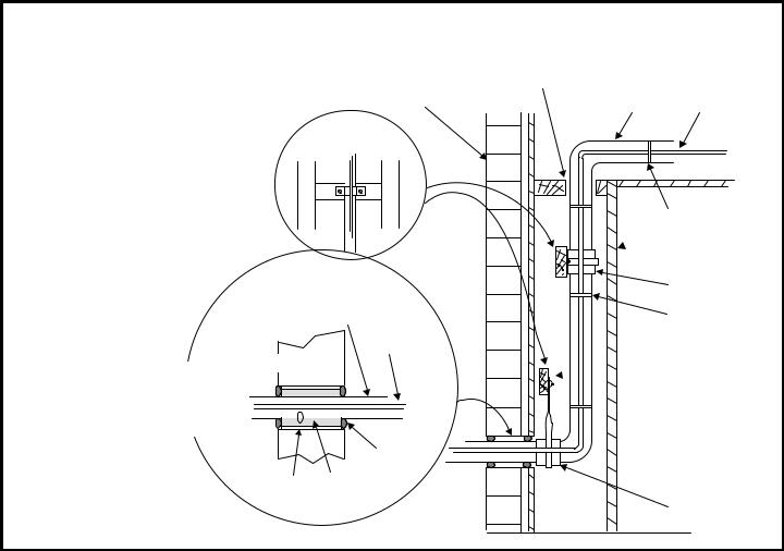
Refrigerant Line Sets: Installing Vertical Runs (new construction shown)
NOTE: Similar installation practices |
Outside Wall |
|
|
||
should be used if line set is to be |
Wood Block |
|
installed on exterior of outside wall. |
||
Between Studs |
||
|
Vapor Line Wrapped
with Armaflex
Liquid Line
Outside Wall
IMPORTANT:
Refrigerant lines must not contact structure.
Caulk
IMPORTANT: Refrigerant lines must not contact wall.
Vapor Line Liquid Line
 Wire Tie
 Inside Wall
 Strap
Strap
Sleeve
Wire Tie
 Wood Block
 Wire Tie
 Strap
Strap
PVC Pipe Fiberglass
Insulation
Sleeve
Figure 8
3.Use silver alloy brazing rods (5% or 6% silver alloy for copper-to-copper brazing or 45% silver alloy for copper-to-brass or copper-to-steel brazing) which are rated for use with HCFC-22 refrigerant.
4.Remove the Schrader core assemblies before brazing to protect them from damage due to extreme heat. Replace the cores when brazing is complete.
5.Wrap a wet cloth around the valve body and copper tube stub to protect them from heat damage during brazing.
6.Braze the line set to the service valve. Quench the joints with water or a wet cloth to prevent heat damage to the valve core and opening port. The tube end must stay bottomed in the fitting during final assembly to ensure proper seating, sealing, and rigidity.
7.Install the factory-supplied fixed orifice (or thermal expansion valve which is sold separately and which is approved for use with HCFC-22 refrigerant) in the liquid line at the indoor coil.
Page 6
Refrigerant Metering Device
2SCU13 units are designed for use with either fixed orifice or TXV systems. Refer to the appropriate following section for information on installing the chosen refrigerant metering device.
Fixed Orifice Systems
2SCU13 units are shipped with a fixed orifice refrigerant metering device. Replace the existing indoor unit fixed orifice with the orifice supplied with this unit. Place the supplied fixed orifice sticker on the indoor cabinet after installation. See Table 3 for the proper fixed orifice size for each unit. In nonstandard applications, the provided fixed orifice may not be appropriately sized.
Install the fixed orifice as shown in Figure 9. Do not twist cap tubes when loosening the seal nut from the orifice housing. Use wrench to back up the distributor.
Expansion Valve Systems
Expansion valves equipped with Chatleff-type fittings are available from the manufacturer. See Table 4 for proper TXV for each unit.
# 48283B006
 Loading...