


£ |
INSTALLATION INSTRUCTIONS
¤1998 Lennox Industries Inc.
Dallas, Texas |
9DOXH% 6HULHV |
|
|
|
|
|
$&% &RQGHQVLQJ 8QLWV |
|
|
&21'(16,1* 81,76 |
|
|
1--1/2 through 5 ton |
|
|
503,800M |
|
|
2/98 |
|
|
Supersedes 503,755M |
/LWKR 8 6 $ |
|
TABLE OF CONTENTS |
|
VALUE 10TM CONDENSING UNIT
Value 10 condensing units are designed for expansion valve (TXV) and RFC systems. Refer to Lennox engineering handbook for expansion valve kits which must be ordered separately.
SHIPPING AND PACKING LIST
1-- Assembled 10ACB condensing unit
1-- 45- copper street elbow
1-- RFCIV refrigerant metering device (bullet) 1-- Coupling -- 5/16 x 3/8” (18, 24, 30)
Check unit for shipping damage. Consult last carrier immediately if damage is found.
GENERAL INFORMATION
These instructions are intended as a general guide and do not supersede national or local codes in any way. Authorities having jurisdiction should be consulted before installation.
 IMPORTANT
The Clean Air Act of 1990 bans the intentional venting of refrigerant (CFC’s and HCFC’s) as of July 1, 1992. Approved methods of recovery, recycling or reclaiming must be followed. Fines and/or incarceration may be levied for non--compliance.
VALUE 10 CONDENSING UNIT . . . . . . . . . . . . . . . . . . . . . 1 SHIPPING AND PACKING LIST . . . . . . . . . . . . . . . . . . . . . . 1 GENERAL INFORMATION . . . . . . . . . . . . . . . . . . . . . . . . . . 1 10ACB UNIT DIMENSIONS . . . . . . . . . . . . . . . . . . . . . . . . . 2 SETTING THE UNIT . . . . . . . . . . . . . . . . . . . . . . . . . . . . . . . . 3 ELECTRICAL . . . . . . . . . . . . . . . . . . . . . . . . . . . . . . . . . . . . . . 3 PLUMBING . . . . . . . . . . . . . . . . . . . . . . . . . . . . . . . . . . . . . . . 4 REFRIGERANT METERING DEVICE . . . . . . . . . . . . . . . . . . 4 MANIFOLD GAUGE SET . . . . . . . . . . . . . . . . . . . . . . . . . . . 5 LIQUID & SUCTION LINE SERVICE VALVES . . . . . . . . . . 5 LEAK TESTING . . . . . . . . . . . . . . . . . . . . . . . . . . . . . . . . . . . . 6 EVACUATION . . . . . . . . . . . . . . . . . . . . . . . . . . . . . . . . . . . . . 7 START-UP . . . . . . . . . . . . . . . . . . . . . . . . . . . . . . . . . . . . . . . . 8 CHARGING CONSIDERATIONS . . . . . . . . . . . . . . . . . . . . . 8 CHARGING FOR RFC SYSTEMS . . . . . . . . . . . . . . . . . . . . 9 CHARGING FOR TXV SYSTEMS . . . . . . . . . . . . . . . . . . . 10 SYSTEM OPERATION . . . . . . . . . . . . . . . . . . . . . . . . . . . . . 10 MAINTENANCE . . . . . . . . . . . . . . . . . . . . . . . . . . . . . . . . . . 11 10ACB CHECK POINTS . . . . . . . . . . . . . . . . . . . . . . . . . . . . 12
RETAIN THESE INSTRUCTIONS
FOR FUTURE REFERENCE
 WARNING
Product contains fiberglass wool.
Disturbing the insulation in this product during installation, maintenance, or repair will expose you to fiberglass wool. Breathing this may cause lung cancer. (Fiberglass wool is known to the State of California to cause cancer.)
Fiberglass wool may also cause respiratory, skin, and eye irritation.
To reduce exposure to this substance or for further information, consult material safety data sheets available from address shown below, or contact your supervisor.
Lennox Industries Inc. P.O. Box 799900 Dallas, TX 75379--9900
3DJH
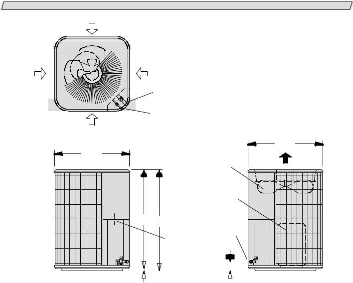
10ACB UNIT DIMENSIONS--INCHES (MM)
INLET 
 AIR
AIR
INLET |
INLET |
|
|
AIR |
AIR |
|
|
|
SUCTION LINE |
|
|
|
CONNECTION |
|
|
|
LIQUID LINE |
|
|
|
CONNECTION |
|
|
INLET |
AIR |
|
|
TOP VIEW |
|
|
|
|
|
24-1/4 |
|
24-1/4 |
|
(616) |
|
|
|
|
|
(616) |
|
|
|
|
OUTDOOR |
DISCHARGE |
AIR |
|
|
|
|
|
COIL FAN |
|
|
COMPRESSOR
* |
|
) |
SUCTION & |
|
|
|
|
|
|
|
|
|
|
|
LIQUID LINE |
|
|
|
CONNECTION |
|
|
|
ELECTRICAL |
|
|
|
INLETS |
|
|
|
|
|
|
|
|
|
|
|
|
|
|
|
|
|
|
|
|
|
|
|
|
|
|
|
|
|
|
|
|
|
|
|
|
|
|
2-3/4 (70) |
|
|
|
|
|
||
|
|
|
|
|
|
|
|
|
|
|
|
|
|
|
|
|
|
|
|
|||
|
|
|
|
|
|
|
|
|
|
|
|
|
|
|
|
|
||||||
|
|
|
|
|
|
|
|
|
|
|
|
|
|
|
|
|
||||||
|
|
|
|
|
|
|
|
|
|
|
|
|
|
|
|
|
||||||
|
SIDE VIEW |
3/4 (19) |
|
|
|
|
|
|
|
|
SIDE VIEW |
|||||||||||
|
|
|
|
|
|
|
|
|
||||||||||||||
|
|
|
|
|
|
|
|
|
|
|
|
|
|
|
|
|
|
|
||||
|
|
|
|
|
|
|
|
|
|
|
|
|||||||||||
|
|
|
|
Model No. |
|
A |
|
|
B |
|
||||||||||||
|
|
|
|
|
|
|
|
|
|
|
|
|
|
|
|
|
|
|
|
|
|
|
|
|
10ACB12 |
|
|
|
|
|
|
|
in. |
|
25 |
|
24-1/4 |
|
|
|
|
||||
|
|
|
|
|
|
|
|
|
|
|
|
|
|
|
|
|||||||
|
|
10ACB18 |
|
|
|
|
|
|
|
|
|
|
|
|
|
|
|
|
|
|
|
|
|
|
10ACB24 |
|
|
|
|
|
|
|
mm |
|
635 |
|
616 |
|
|
|
|
|
|||
|
|
10ACB30 |
|
|
|
|
|
|
|
|
|
|
|
|
|
|
||||||
|
|
|
|
|
|
|
|
|
|
|
|
|
|
|
|
|
|
|
|
|
|
|
|
|
|
|
|
|
|
|
|
|
|
|
|
|
|
|
|
|
|
|
|
|
|
|
|
10ACB36 |
|
|
|
|
|
|
|
in. |
|
33 |
|
32-1/4 |
|
|
|
|
||||
|
|
10ACB42 |
|
|
|
|
|
|
|
|
|
|
|
|
|
|||||||
|
|
|
|
|
|
|
|
|
|
|
|
|
|
|
|
|
|
|
|
|
|
|
|
|
10ACB48 |
|
|
|
|
|
|
|
|
|
|
|
|
|
|
|
|
|
|
|
|
|
|
|
|
|
|
|
|
|
|
|
|
|
|
|
|
|
|
|
|
|
|
|
|
|
10ACB60 |
|
|
|
|
|
|
|
mm |
|
838 |
|
819 |
|
|
|
|
|
|||
|
|
10ACB62 |
|
|
|
|
|
|
|
|
|
|
|
|
|
|
||||||
|
|
|
|
|
|
|
|
|
|
|
|
|
|
|
|
|
|
|
|
|
|
|
|
|
|
|
|
|
|
|
|
|
|
|
|
|
|
|
|
|
|
|
|
|
|
3DJH

SETTING THE UNIT
Refer to unit dimensions on page 2 for sizing mounting slab, platforms or supports. Refer to figure 1 for installation clearances.
INSTALLATION CLEARANCES
36
(914 mm)
(91436mm) |
*36
(914 mm)
(914*36mm) |
NOTE—48 inch clearance required on top of unit. *NOTE—One side must be 36 inches. Two side may be 12”.
FIGURE 1
Slab Mounting
When installing unit at grade level, install on a level slab high enough above grade to allow adequate drainage of water. Top of slab should be located so run--off water from higher ground will not collect around unit.
Roof Mounting
Install unit at a minimum of 4 inches above the surface of the roof. Care must be taken to ensure weight of unit is properly distributed over roof joists and rafters. Either redwood or steel supports are recommended.
ELECTRICAL
In the U.S.A., wiring must conform with current local codes and the current National Electric Code (NEC). In Canada, wiring must conform with current local codes and the current Canadian Electrical Code (CEC). Refer to the furnace or blower coil installation instructions for additional wiring application diagrams and refer to unit rating plate for minimum circuit ampacity and maximum overcurrent protection size.
 WARNING
Unit must be grounded in accordance with national and local codes. Electric Shock Hazard.
Can cause injury or death.
Line Voltage
To facilitate conduit, a hole is provided in bottom of the control box. Connect conduit to hole in control box with proper conduit fitting.
127( 8QLWV DUH DSSURYHG IRU XVH ZLWK FRSSHU FRQGXF WRUV RQO\
24V, Class II Circuit
24V, Class II Circuit connections are made up in the low voltage junction box. Refer to figure 2 for field wiring diagram.
NOTE -- A complete unit wiring diagram is located inside the unit control box cover.
10ACB TYPICAL FIELD WIRING DIAGRAM
NOTE--SEE UNIT WIRING DIAGRAM |
|
|
FOR POWER SUPPLY CONNECTIONS. |
ROOM THERMOSTAT |
|
CONDENSING UNIT |
|
|
+ |
; / 9 4+ |
40 |
Y1
C
TO 24V CLASS II POWER SOURCE
-- 20 VA MINIMUM
NOTE--IF INDOOR UNIT IS NOT EQUIPPED WITH
BLOWER RELAY, IT MUST BE FIELD PROVIDED
AND INSTALLED (P--8--3251 OR EQUIVALENT)
24V CLASS II INSTALLED AT FACTORY
24V CLASS II FIELD INSTALLED
TYPICAL INDOOR UNIT
|
|
|
|
|
|
|
|
|
|
|
|
|
|
|
|
|
|
|
|
|
|
|
|
|
TRANSFORMER |
||||
|
|
R |
|
|
|
|
|
|
|
|
|
|
|
|
|
|
|
|
|
|
|
|
|||||||
|
|
|
|
|
|
|
|
|
|
|
|
|
|
|
|
|
|
|
|
|
|
|
|
|
|
|
|
|
T1 |
|
|
|
|
|
|
|
|
|
|
|
|
|
|
|
TO |
|
|
|
|
|
24v |
||||||||
|
|
|
|
|
|
|
|
|
|
|
|
|
|
|
|
|
|
|
|
|
|||||||||
|
W1 |
|
|
|
HEATING |
|
TO |
|
|
|
|
||||||||||||||||||
|
|
|
|
|
|
|
|
||||||||||||||||||||||
|
|
|
|
|
|
|
|
|
|
|
|
CONTROLS |
|
|
|
|
|
||||||||||||
|
|
|
|
|
|
|
|
|
|
|
|
||||||||||||||||||
G
 COOLING
|
SPEED |
|
W2 |
TO |
|
|
|
|
|
HEATING |
|
|
SPEED |
GROUND |
|
|
CPER NATIONAL AND LOCAL
CODES
24V |
POWER |
CLASS II |
|
JUNCTION |
|
BOX |
|
K3 INDOOR BLOWER RELAY
FIGURE 2
3DJH
PLUMBING
Field refrigerant piping consists of liquid and suction lines from the condensing unit (sweat connections) to the indoor evaporator coil (flare or sweat connections). Use Lennox L10 (flare) or L15 (sweat, non-flare) series line sets as shown in table 1 or use field-fabricated refrigerant lines. Refer to unit information manual piping section for proper size, type and application of field-- fabricated lines.
Sweat Connection Procedure
1-- Ends of refrigerant lines must be cut square, free from nicks or dents, deburred. Pipe must remain round, do not pinch end of line.
2-- Wrap a wet cloth around the liquid line valve body and copper tube stub to protect from heat damage during brazing. Wrap another wet cloth underneath the liquid valve to protect the base paint.
3-- Quench the joints with a wet cloth to prevent possible heat damage to the valve core and opening port.
4-- A field provided filter drier should be installed as close as possible to the expansion device.
REFRIGERANT METERING DEVICE
10ACB units are applicable to either RFCIV or an expansion valve system. See indoor coil installation instructions and the Lennox engineering handbook for approved RFC and TXV match-ups and application information. Table 1 lists 10ACB unit liquid and suction line sizes and corresponding line sets.
TABLE 1
REFRIGERANT LINE KITS
UNIT |
LIQUID |
SUCTION |
L10 |
L15 |
|
LINE |
LINE |
LINE SETS |
LINE SETS |
|
|
|
|
||||
|
|
|
|
||
|
|
|
|
|
|
10ACB18 |
5/16 in* |
5/8 in |
L10--21 |
L15--21 |
|
20 ft. -- 50 ft. |
20 ft. -- 50 ft. |
|
|||
|
|
||||
10ACB24 |
(8 mm) |
(16 mm) |
|
||
(6 m -- 15 m) |
(6 m -- 15 m) |
|
|||
|
|
|
|
||
10ACB30 |
3/8 in |
3/4 in. |
L10--41 |
L15--41 |
|
20 ft. -- 50 ft. |
20 ft. -- 50 ft. |
|
|||
10ACB36 |
(10 mm) |
(19 mm) |
|
||
(6 m -- 15 m) |
(6 m -- 15 m) |
|
|||
|
|
|
|
||
10ACB42 |
3/8 in |
7/8 in. |
L10--65 |
L15--65 |
|
30 ft. -- 50 ft. |
30 ft. -- 50 ft. |
|
|||
10ACB48 |
(10 mm) |
(22 mm) |
|
||
(9 m -- 15 m) |
(9 m -- 15 m) |
|
|||
|
|
|
|
||
10ACB60 |
3/8 in |
1--1/8 in. |
FIELD |
FIELD |
|
10ACB62 |
(10 mm) |
(29 mm) |
FABRICATED |
FABRICATED |
|
*Use reducer supplied in bag assembly.
NOTE -- Line length should be no greater than 50 feet (15.2 m). Select line set diameters from table 1 to ensure oil return to compressor.
RFC Systems
10ACB units are shipped with an RFCIV metering device. Replace existing RFCIV in indoor unit with RFCIV supplied with the outdoor unit. Place the supplied RFCIV sticker on indoor cabinet after installation. See table 2 for size of RFCIV bullet shipped in each 10ACB unit. In cases of non-traditional applications, RFCIV bullet shipped may not be appropriate. Refer to the indoor coil installation instructions and the engineering handbook for specific orifice information.
7$%/( 5)&,9 '5,// 6,=(6
10ACB UNIT |
RFCIV PART # |
RFCIV DRILL SIZE |
|
|
|
|
|
|
10ACB12 |
42J35 |
0.047 |
|
|
|
10ACB18 |
42J39 |
0.055 |
|
|
|
10ACB24 |
66J87 |
0.062 |
|
|
|
10ACB30 |
42J45 |
0.067 |
|
|
|
10ACB36 |
42J48 |
0.073 |
|
|
|
10ACB42 |
42J52 |
0.080 |
|
|
|
10ACB48 |
42J54 |
0.084 |
|
|
|
10ACB60 |
42J58 |
0.092 |
|
|
|
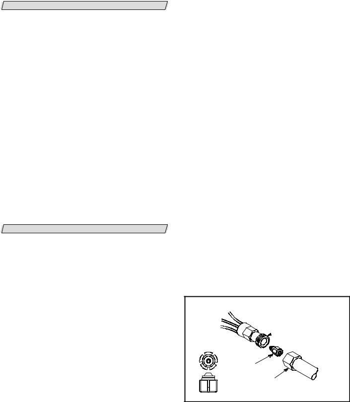
RFCIV bullet is installed as shown in figure 3. Take care not to twist cap tubes when loosening seal nut from orifice body.
4.CIV INSTALLATION
ORIFICE
 BODY
BODY
DISTRIBUTOR
“BULLET” ORIFICE
SEAL
NUT SWEAT
CONNECTION
FIGURE 3
3DJH
 Loading...