


 Loading...
ETS Installation Guide
For ETS8PS, ETS16PS, ETS16PR, and ETS32PR
Multiport Device Servers
Part Number 900-401
Revision A April 2005
Copyright and Trademark
The information in this guide may change without notice. The manufacturer assumes no responsibility for any errors which may appear in this guide.
AppleTalk, Chooser, and Macintosh are trademarks of Apple Computer Corp. LaserJet and Bitronics are trademarks of Hewlett Packard. Centronics is a registered trademark of Centronics Data Computer Corp. PostScript is a trademark of AdobeSystems, Inc. DEC and LAT are trademarks of Digital Equipment Corporation. Ethernet is a trademark of XEROX Corporation. NetWare is a trademark of Novell Corporation. UNIX is a registered trademark of The Open Group. Windows for Workgroups, Windows 95, Windows 98, Windows 2000, and Windows NT are trademarks of Microsoft Corporation.
Copyright 2004, Lantronix. All rights reserved. No part of the contents of this book may be transmitted or reproduced in any form or by any means without the written permission of Lantronix. Printed in the United States of America.
Contacts
Lantronix Corporate Headquarters
15353 Barranca Parkway Irvine, CA 92618, USA Phone: 949-453-3990 Fax: 949-453-3995
Technical Support
Phone: 800-422-7044 or 949-453-7198 Fax: 949-450-7226
Online: www.lantronix.com/support Email support@lantronix.com
Sales Offices
For a current list of our domestic and international sales offices, go to the Lantronix web site at http://www.lantronix.com/about/contact/index.html
ETS Installation Guide |
2 |
Disclaimer and Revisions
This product has been designed to comply with the limits for a Class A digital device pursuant to Part 15 of FCC Rules. These limits are designed to provide reasonable protection against such interference when operating in a commercial environment. This equipment generates, uses, and can radiate radio frequency energy, and if not installed and used in accordance with this guide, may cause harmful interference to radio communications.
Operation of this equipment in a residential area is likely to cause interference in which case the user, at his or her own expense, will be required to take whatever measures may be required to correct the interference.
Changes or modifications to this device not explicitly approved by Lantronix will void the user's authority to operate this device.
Cet appareil doit se soumettre avec la section 15 des statuts et règlements de FCC. Le fonctionnement est subjecté aux conditions suivantes:
(1)Cet appareil ne doit pas causer une interférence malfaisante.
(2) Cet appareil doît accepter n'importé quelle interférence reìue qui peut causer une opération indésirable.
The information in this guide may change without notice. The manufacturer assumes no responsibility for any errors that may appear in this guide.
Date |
Rev. |
Comments |
4/05 |
A |
Initial Document |
ETS Installation Guide |
3 |

Contents
1: Introduction |
7 |
Supported Serial Protocols _______________________________________________ 7
RS-232 ____________________________________________________________________ 7 RS-423 ____________________________________________________________________ 7
How to Use This Manual _________________________________________________ 8
2: Installation |
9 |
ETSP Product Descriptions _______________________________________________ 9
ETSPS Front Panels _________________________________________________________ 9 ETS8PS/ETS16PS LEDs______________________________________________________ 9 ETS8PS Back Panel _________________________________________________________ 9 ETS16PS Back Panel _______________________________________________________ 10
Installing the ETSP ____________________________________________________ 10 ETSPR Product Descriptions_____________________________________________ 11
ETS16PR Front Panel _______________________________________________________ 11 ETS32PR Front Panel _______________________________________________________ 12 ETSPR LEDs ______________________________________________________________ 12
Installing the ETSPR ___________________________________________________ 12
3: Getting Started |
15 |
Configuration Methods__________________________________________________ 15
EZWebCon________________________________________________________________ 15 Using a Web Browser (ETSPR models) _________________________________________ 15 Incoming Logins ____________________________________________________________ 16 Console Terminal ___________________________________________________________ 16
TCP/IP Configuration ___________________________________________________ 16
Using EZWebCon___________________________________________________________ 16 Using a Directed Ping Packet _________________________________________________ 17 Using a BOOTP, DHCP, or RARP Reply_________________________________________ 18 Using the Command Line Interface _____________________________________________ 18
Services _____________________________________________________________ 18 Was the Installation Successful? __________________________________________ 18
4: Using the ETS |
19 |
Console Server Example ________________________________________________ 19
Define the Menus ___________________________________________________________ 20 Enable Menu Mode _________________________________________________________ 21 Configure Switches _________________________________________________________ 21 Using Menus ______________________________________________________________ 22
Serial Tunnel Example__________________________________________________ 23
TCP Configuration __________________________________________________________ 23 UDP Configuration __________________________________________________________ 24 Multi-port Serial Tunnel Configuration ___________________________________________ 24 Comm Port Redirector _______________________________________________________ 24
ETS Installation Guide |
4 |

Contents
5: Printing on the ETS |
25 |
LPR Printing __________________________________________________________25
LPR on Windows NT 3.5.1 (and later) ___________________________________________25 LPR on Windows 95/98 ______________________________________________________32 LPR on UNIX Hosts _________________________________________________________32 LPR on AIX Hosts ___________________________________________________________33 LPR on HP Hosts ___________________________________________________________34 LPR on SCO UNIX Hosts _____________________________________________________34 RTEL Functionality __________________________________________________________35
Unix Host Troubleshooting _______________________________________________36
6: NetWare Configuration |
37 |
NDPS Printing _________________________________________________________37 NDS Print Queues ______________________________________________________37
Obtain an NDS License ______________________________________________________37 Configure your ETS _________________________________________________________37
NetWare Administrator Quick Setup Print Queues _____________________________38 PCONSOLE Print Queues________________________________________________38 NetWare Host Troubleshooting ____________________________________________39
7: LAT Configuration |
42 |
Printing Directly to a Port_________________________________________________42 LAT Host Troubleshooting________________________________________________42
8: AppleTalk Configuration |
44 |
Bitronics______________________________________________________________44 Macintosh Services _____________________________________________________44 AppleTalk Zones _______________________________________________________44 AppleTalk Host Troubleshooting ___________________________________________45
9: DLC Configuration for LAN Manager |
46 |
DLC Configuration ______________________________________________________46
ETS Configuration___________________________________________________________46 Host Configuration __________________________________________________________46
A: Contact Information |
47 |
B: Troubleshooting |
48 |
Power-up Troubleshooting _______________________________________________48 DHCP Troubleshooting __________________________________________________49 BOOTP Troubleshooting _________________________________________________49 RARP Troubleshooting __________________________________________________50 Entering Commands at the Boot Prompt_____________________________________50
C: Pinouts |
53 |
Ethernet Connector _____________________________________________________53 RJ45 Serial Connectors__________________________________________________53
RJ45 to DB25 ______________________________________________________________53 RJ45 to DB9 _______________________________________________________________55
D: Updating Software |
56 |
ETS Installation Guide |
5 |

Contents
Choosing the Right Software File__________________________________________ 56 Obtaining Software ____________________________________________________ 56
Via the Web _______________________________________________________________ 56 Via FTP __________________________________________________________________ 56
Reloading Software ____________________________________________________ 57
Reloading Sequence ________________________________________________________ 57 TCP/IP ___________________________________________________________________ 57 NetWare __________________________________________________________________ 58 MOP _____________________________________________________________________ 58
Troubleshooting Flash ROM Updates ______________________________________ 59
E: Specifications |
60 |
Power Information _____________________________________________________ 60
Power Requirements ________________________________________________________ 60 Power Supply Cord _________________________________________________________ 60
Environmental Limitations _______________________________________________ 60
Temperature_______________________________________________________________ 60 Altitude ___________________________________________________________________ 60 Relative Humidity ___________________________________________________________ 60
F: Frequently-used Commands |
61 |
Conventions __________________________________________________________ 61 Server Commands _____________________________________________________ 61 Port Commands _______________________________________________________ 64 Protocol Commands ___________________________________________________ 65
G: Compliance and Warranty Information |
67 |
Declaration of Conformity _______________________________________________ 67 Warranty ____________________________________________________________ 68
6 |
ETS Installation Guide |

1: Introduction
The Lantronix ETS (ETS8PS, ETS16PS, ETS16PR, and ETS32PR) is a multi-port device server providing shared network access to terminals, devices, console ports, and printers for a variety of network protocols and operating systems. The ETS supports the TCP/IP, IPX (NetWare), Local Area Transport (LAT), AppleTalk (EtherTalk), and Microsoft LAN Manager protocols.
Note: In this manual, all ETS servers will be referred to as “the ETS” unless a distinction needs to be made between models.
The ETS stores its executable software in Flash (rewritable) ROM, meaning that it does not have to download software from a host each time it boots. Software must only be downloaded when a new software version becomes available. See D:Updating Software for more information.
Supported Serial Protocols
All ETS models support the RS-232/423 serial protocol.
RS-232
The RS-232 line interface standard is a single-ended peer-to-peer interface. Today's personal computers typically have at least one RS-232 serial port. It is the most common serial protocol used today.
RS-232 is used for connecting devices across short distances at speeds up to 230.4 kb/s. Faster speeds require shorter cabling to ensure error-free communication. The maximum cable length at a given speed is determined by many factors, including the immediate electrical environment and the quality of cable used, but is usually less than 15 meters at high speeds.
RS-423
All of the ETS models support the RS-423 line interface standard. RS-423 devices are interoperable with RS-232 devices. That is, RS-232 ports can receive data reliably from RS-423 ports and vice-versa.
The main difference between RS-423 and RS-232 is that RS-423 employs lower voltage signaling and differential receivers. RS-423 still uses single-ended transmitters for compatibility with RS-232 receivers.
RS-423 is generally rated at higher speeds over longer cabling runs than RS-232. Maximum data rates of 230.4 kb/s are possible on ETS-PR models, and 115.2 kb/s is the maximum on ETS-P models.
ETS Installation Guide |
7 |

Introduction
How to Use This Manual
2:Installation
3:Getting Started
4:Using the ETS
5:Printing on the ETS 6:NetWare Configuration 7:LAT Configuration 8:AppleTalk Configuration
9:DLC Configuration for LAN Manager
Explains how to physically install the ETS.
Explains the minimum configuration needed.
Explains some of the ways that you can use your ETS.
Chapters 5 through 9 cover protocol-specific setup needed to install print queues and otherwise use the ETS.
A:Contact Information
B:Troubleshooting
C: Pinouts
D:Updating Software
E:Specifications
F:Frequently-Used Commands
G:Compliance and Warranty Information
Appendices A through F provide supplementary information.
Read chapters 2 through 4 in order, then proceed to the protocol-specific chapter that relates to your network. Refer to F:Frequently-Used Commands as needed. The Device Server Reference Manual, located on the CD-ROM and web site, provides additional information about configuring and using your ETS.
8 |
ETS Installation Guide |

2: Installation
This chapter describes the various ETS models and shows how to install them into a basic network configuration. The ETSPS models will be explained first. For ETSPR descriptions and installation instructions, skip to ETSPR Product Descriptions.
ETSP Product Descriptions
ETSPS Front Panels
The front panel of all ETSP models has a Test/Reset button (called Reset on the ETS8PS and ETS16PS), seven LEDs, and a power switch. Pressing the Reset button for 5 seconds while the unit powers up will flush the NVR (factory reset).
ETS8PS/ETS16PS LEDs
The seven LEDs are explained in the following table.
Table 2-1. ETS8PS/ETS16PS LED Functionality
LED |
Function |
PWR |
Lights to indicate the ETS has power |
|
|
LNK |
Lights to indicate a functional 10BASE-T |
|
network link |
POL |
Lights to indicate a swapped 10BASE-T cable |
OK |
Blinks to indicate that the ETS is functioning |
|
properly |
NET |
Blinks to indicate Ethernet activity |
RCV |
Blinks periodically to indicate serial characters |
|
entering the ETS |
XMT |
Blinks periodically to indicate serial characters |
|
exiting the ETS |
ETS8PS Back Panel
The back panel of the ETS8PS has a power plug, an AUI Ethernet port, an RJ45 10BASE-T Ethernet port, and eight RJ45 serial ports.
ETS Installation Guide |
9 |

Installation
Figure 2-1. ETS8PS and ETS16PS Back Panels
ETS16PS Back Panel
The back panel of the ETS16PS has a power plug, an AUI Ethernet port, a 10BASE- T Ethernet port, and 16 RJ45 serial ports.
Figure 2-2. ETS16PS Back Panel
Installing the ETSP
The following two diagrams show properly-installed ETSP servers.
Figure 2-3. Sample ETS8P/ETS16PS Network Layout (ETS8PS shown)
10 |
ETS Installation Guide |
Installation
To install the ETS, complete the following steps in order. Refer to the numbers in the previous figure.
1.Select a location for the ETS.
When choosing a location, keep in mind the environmental restrictions discussed in E:Specifications.
2.Connect one or more serial devices to the ETS.
Note: The default serial port settings are 9600 baud, 8 bit characters, no parity, 1 stop bit, and Xon-Xoff flow control. See C:Pinouts for information on what kinds of device attachments the ETS supports.
3.It is recommended to connect a terminal to the ETS console port (port 1). This will enable you to receive diagnostic and initial configuration messages.
4.Connect an Ethernet cable to either the 10BASE-T port (shown) or a transceiver connected to the AUI port.
Note: The ETS will boot without a valid Ethernet connection, but it will pause to print a message (seen on the console port) asking if you want to stop at the Boot> prompt. If you do not respond to this message, it will wait for 10 seconds and then finish booting.
5.Attach one end of the power cable to the ETS and plug the other end into an electrical outlet.
6.Flip the power switch to turn the unit ON. The ETS will go through two steps to begin normal operation:
a)It runs through a set of power-up diagnostics for approximately 12 seconds. The LEDs show varying patterns corresponding to the tests being run.
b)It tries to obtain TCP/IP configuration information via DHCP, BOOTP, and RARP. This may take as long as 15 seconds if no hosts answer the requests. During this step, the OK LED blinks approximately 3 times per second and the NET LED blinks occasionally.
7.Install EZWebCon on your 32-bit Windows PC computer. The EZWebCon software is located on the distribution CD-ROM. Alternatively, download it from ftp://ftp.lantronix.com.
ETSPR Product Descriptions
ETS16PR Front Panel
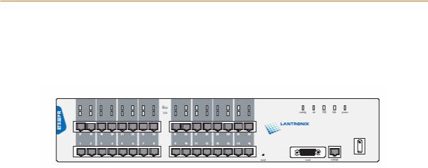
The ETS16PR has 16 RJ45 serial ports, a Reset button, an AUI Ethernet port, an RJ45 Ethernet port for 10/100BASE-T, several LEDs, and a power switch.
Figure 2-4. ETS16PR Front Panel
Note: The first RJ45 port is also the serial console port. Use it as a method for the initial setup or troubleshooting.
ETS Installation Guide |
11 |
Installation
ETS32PR Front Panel
The ETS32PR has 32 RJ45 serial ports, a Reset button, an AUI Ethernet port, an RJ45 Ethernet port for 10/100BASE-T, several status LEDs, and a power switch.
Figure 2-5. ETS32PR Front Panel
Note: The first RJ45 port is also the serial console port. Use it as a method for the initial setup or troubleshooting.
ETSPR LEDs
Each ETSPR has a total of 37 LEDs. Each serial port has one (ETS32PR) or two (ETS16PR) corresponding LEDs that indicate receive and transmit activity, and there are five status LEDs on the right side of the case.
|
Table 2-2. ETSPR Port LED Functionality |
|
|
|
|
LED |
|
Function |
activity |
|
Blinks to indicate Ethernet activity |
ok |
|
Blinks to indicate that the ETS is functioning |
|
|
properly |
100 |
|
Lights to indicate a 100BASE-T rather than |
|
|
10BASE-T Ethernet link |
link |
|
Lights to indicate a functional Ethernet |
|
|
network link |
power |
|
Lights to indicate the ETS has power |
|
|
|
Installing the ETSPR
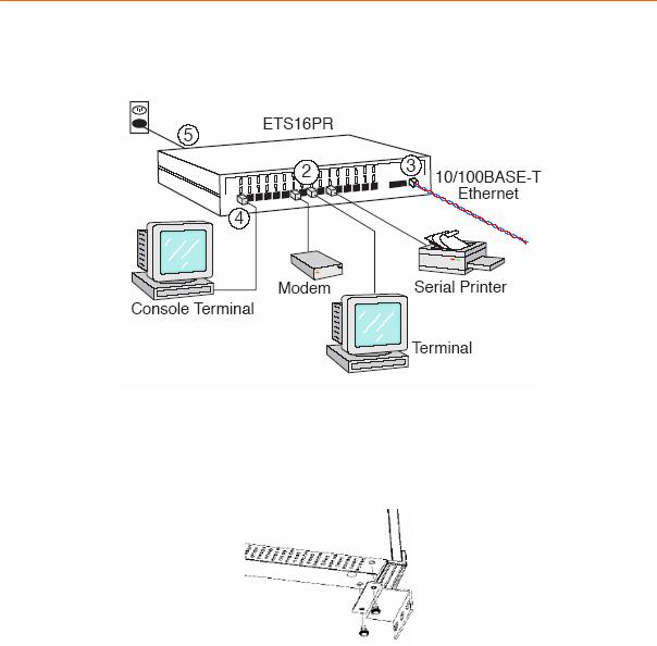
The following diagram shows a properly-installed ETS16PR. Installation will generally be the same for all ETSPR models, the only difference being the number of serial ports available. See ETSPR Product Descriptions on page 11 for more information.
12 |
ETS Installation Guide |
Installation
Figure 2-6. Sample ETSPR Network Layout (ETS16PR shown)
To install the ETS, complete the following steps in order:
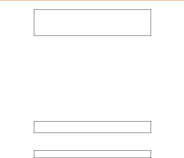
1.Attach the two rack mount brackets to your ETS and attach your bracketed ETS to your rack. The brackets should go on both front corners or both rear corners. (This is only necessary if you would like to mount the unit on a rack.)
Figure 2-7. Rack Mount Bracket Installation
2.Connect one or more serial devices to the ETS.
Note: The default serial port settings are 9600 baud, 8 bit characters, no parity, 1 stop bit, and Xon-Xoff flow control. See C:Pinouts for information on what kinds of device attachments the ETS supports.
3.It is recommended to connect a terminal to the ETS console port (port 1). This will enable you to receive diagnostic and initial configuration messages.
4.Connect an Ethernet cable to either the 10BASE-T port (shown) or a transceiver connected to the AUI port.
Note: The ETS will boot without a valid Ethernet connection, but it will pause to print a message (seen on the console port) asking if you want to stop at the Boot> prompt. If you do not respond to this message, it will wait for 10 seconds and then finish booting.
5.Attach one end of the power cable to the ETS and plug the other end into an electrical outlet.
6.Flip the power switch to turn the unit ON. The ETS will go through two steps to begin normal operation:
ETS Installation Guide |
13 |

Installation
a)It runs through a set of power-up diagnostics for approximately 12 seconds. The LEDs show varying patterns corresponding to the tests being run.
b)It tries to obtain TCP/IP configuration information via DHCP, BOOTP, and RARP. This may take as long as 15 seconds if no hosts answer the requests. During this step, the OK LED blinks approximately 3 times per second and the NET LED blinks occasionally.
7.Install EZWebCon on your 32-bit Windows PC computer. The EZWebCon software is located on the distribution CD-ROM. Alternatively, download it from ftp://ftp.lantronix.com.
14 |
ETS Installation Guide |

3: Getting Started
It is important to consider the following points before logging into and configuring the ETS:
You must configure the ETS IP address before any TCP/IP functionality is available. You cannot use the ThinWeb Manager until you have configured an IP address.
Changing any server, service, or port setting requires privileged user status. The default privileged password is system.
The login password is required for remote console logins. The default login username is access. The login password is not required by default.
Note: If you would like to change either the privileged or login password, either use EZWebCon or refer to the Device Server Reference Manual located on the CD-ROM.
Configuration Methods
EZWebCon
The EZWebCon configuration software is the recommended way to configure the ETS. EZWebCon’s graphical user interface guides first time users through the initial configuration process and allows experienced users to update any configurable parameters.
EZWebCon requires a Java Virtual Machine (JVM) on the client. Lantronix provides JVM installers for Solaris and 32-bit Windows users, as well as source code and instructions for compiling it for other systems.
The EZWebCon software is located on the distribution CD-ROM. All instructions for installing EZWebCon are provided in the README file. For assistance once EZWebCon is running, refer to the EZWebCon on-line help.
Note: EZWebCon is also available from the Lantronix website and FTP server. See D:Updating Software for more information.
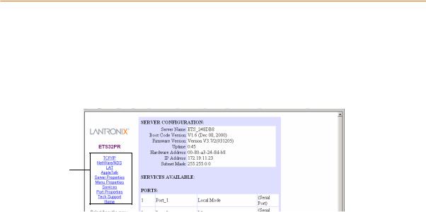
Using a Web Browser (ETSPR models)
The ThinWeb Manager web browser interface allows you to log into and configure your ETS using a standard web browser with JavaScript enabled. Simply type the ETS IP address or resolvable text name into the browser’s URL/Location field (for example, http://111.222.333.444).
Figure 3-1. Sample Web Browser Login
ETS Installation Guide |
15 |
Getting Started
Once you have connected to the ETS, you will see the Lantronix ThinWeb Manager interface. Use the left-hand menu to navigate to subpages where you can configure important settings as well as view statistics and other server information.
Note: Do not use the ThinWeb Manager until the IP is configured. See TCP/IP Configuration.
Figure 3-2. ThinWeb Manager Interface
MENU
Incoming Logins
Incoming logins made via EZWebCon can be used to configure the ETS. Incoming LAT and TCP/IP logins can also be used.
Incoming Telnet is only possible if your ETS has an IP address configured. Incoming Telnet is enabled by default to allow TCP/IP connections. To change this setting, use the Define Server Incoming command described in the Command Reference chapter of the Device Server Reference Manual located on the CD-ROM.
Incoming logins do not prompt for a login password, so you may wish to disable them for security reasons. If it is undesirable to disable incoming logins, the ETS can be configured to prompt for a password with the Define Server Incoming Password Enabled command.
Console Terminal
To configure the ETS via a console terminal, attach a terminal to the serial console port (port 1) and press the Return key. You will see a Local> prompt at which you can enter configuration commands.
TCP/IP Configuration
The EZWebCon configuration software is the easiest way to configure the ETS. The following sections cover IP address configuration methods for TCP/IP hosts.
The ETS IP address must be configured before any TCP/IP functionality is available. Use one of the following methods to set the IP address: EZWebCon; a directed Ping packet; a BOOTP, DHCP, or RARP reply; or commands entered via the command line interface on a terminal console.
Using EZWebCon
Use the following steps to assign an IP address using the EZWebCon Expert Shell.
1.From the Action menu, select Assign IP Address.
2.Enter or change the IP-related settings:
a)For Ethernet Address, enter the number that appears on the bottom label of your ETS.
16 |
ETS Installation Guide |

Getting Started
b)For IP Address, enter the desired IP address to use for this ETS. The IP address should be on the same subnet as the PC running EZWebCon.
c)For Subnet Mask, change the values provided only if you wish to use a mask other than the default. The default value should be correct in most cases.
d)For Loadhost, enter the IP address of the loadhost where you intend to store your operating code.
3.Click OK.
4.Reboot the ETS. EZWebCon will let you know whether the configuration was successful.
Note: If you have an older version of EZWebCon, refer to the ReadMe that was included with it.
Using a Directed Ping Packet
The ARP/ping method is available under UNIX and Windows-based systems. If the ETS has no IP address, it will set its address from the first directed IP packet it receives.
On a UNIX host, create an entry in the host’s ARP table and substitute the intended IP address and the hardware address of the ETS, then ping the ETS. This process typically requires superuser privileges. The IP address should be on the same subnet as the PC running EZWebCon.
Figure 3-3. ARP and Ping on UNIX
# arp -s 192.0.1.228 00:80:a3:xx:xx:xx % ping 192.0.1.228
In order for the ARP command to work on Windows 95, the ARP table on the PC must have at least one IP address defined other than its own. If the ARP table is empty, the command will return an error message. Type ARP -A at the DOS command prompt to verify that there is at least one entry in the ARP table.
Figure 3-4. ARP and Ping on Windows
C:\ ARP -S 192.0.1.228 00-80-A3-XX-XX-XX
C:\ PING 192.0.1.228
Note: There should be replies from the IP address if the ARP command worked.
When the ETS receives the ping packet, it will notice that its IP address is not set and will send out broadcasts to see if another node is using the specified address. If no duplicate is found, the ETS will use the IP address and will respond to the ping packet.
The ETS will not save the learned IP address permanently; this procedure is intended as a temporary measure to enable EZWebCon to establish communication and allow an administrator to Telnet into the ETS. Once logged in, the administrator can enter the Define Server IPaddress command to make the address permanent.
Figure 3-5. Configuring Permanent IP Address
% telnet 192.0.1.228
Trying 192.0.1.228
Lantronix ETSx Version n.n/n (yymmdd)
ETS Installation Guide |
17 |
Getting Started
Type Help at the ‘Local_>’ prompt for assistance.
Enter Username> gopher
Local> SET PRIVILEGED
Password> system (not echoed)
Local>> DEFINE SERVER IPADDRESS 192.0.1.228
Local>> DEFINE SERVER SUBNET MASK 255.255.255.0
Any host wishing to access the ETS will have to be told the ETS’ IP address. This is typically configured in the UNIX file /etc/hosts or via a nameserver. Refer to the host’s documentation for additional information.
Using a BOOTP, DHCP, or RARP Reply
At boot time a host-based DHCP, BOOTP, or RARP server can respond to an ETS request for an available IP address. For information about configuring the DHCP, BOOTP, or RARP server, see your host documentation.
Using the Command Line Interface
1.Connect to the serial port (Port_1) using a console terminal or a terminal emulation program, and press Enter. The serial port settings are 9600 baud, 8 bits, 1 stop bit, no parity.
2.Become the privileged user.
Figure 3-6. Becoming the Privileged User
Local> SET PRIVILEGED
Password> system (not echoed)
Local>>
3. Enter the new IP address.
Figure 3-7. Configuring the IP Address
Local>> define server ipaddress 192.0.1.201
Local>> DEFINE SERVER SUBNET MASK 255.255.255.0
For additional command line reference (for use with Telnet or a terminal console), see the ETS Reference Manual available for download from www.lantronix.com/support/docs/index.html .
Was the Installation Successful?
If the ETS appears to be working and the unit is connected to the network, there are a couple of ways to confirm that the unit is visible to network hosts:
If the ETS has an IP address, ping it from a TCP/IP host.
If the ETS has an IP address, use EZWebCon to log into it.
When you are satisfied that the ETS is working properly, proceed to 3:Getting Started. If the ETS does not boot properly, see B:Troubleshooting.
18 |
ETS Installation Guide |
4: Using the ETS
The sections in this chapter show how to use the ETS in a variety of applications.
For detailed instructions on how to set up the ETS as a console server, see Console Server Example.
For instructions on how to use the ETS in serial tunnel mode, see Serial Tunnel Example on page 23.
For information about using the ETS with the Lantronix Comm Port Redirector, see
Comm Port Redirector on page 24.
Keep in mind that you must reboot the ETS after issuing a Define command. The command will take effect when the ETS reboots. The one exception is that Define Port commands take effect when a port is logged out.
Console Server Example
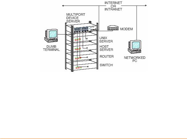
When you use the ETS as a console server, you can remotely manage devices and equipment from anywhere on the network.
Figure 4-1. Console Server
To use the ETS as a console server, you must connect the ETS serial ports to the serial console/management ports of other equipment such as UNIX servers, PBX switches, routers, network switches, or other similar devices.
Once you have completed the connections, you can establish a Telnet connection to the ETS IP address and socket number of the desired port. The ETS serial ports allow two types of socket connections: Telnet IAC interpretation at socket 200x, and raw TCP connections at socket 300x, where x is the port number. For example, to open a Telnet connection to port 4 of an ETS at IP address 192.0.1.168, you would issue the command “Telnet 192.0.1.168 2004” from your system prompt. In a Windows environment, use a space instead of a colon in the command syntax.
ETS Installation Guide |
19 |
Using the ETS
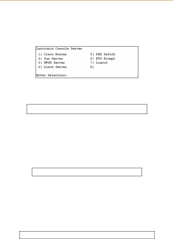
In addition to direct Telnet connections, you can use the ETS’ built-in menu feature. The ETS menu allows you to connect to the IP address of the ETS and be greeted with a menu with which to connect to each attached serial device. Menu choices are an easy way to let users access often-used hosts and services without needing to know any ETS command syntax, the IP addresses of the non-local devices, or the socket numbers involved.
Figure 4-2. Sample Menu
Define the Menus
To give your menu a name, use a Define Menu Title command.
Figure 4-3. Menu Title
Local>> DEFINE MENU TITLE “Lantronix Console Server:”
Create menus entries with the Define Menu command. (To temporarily test menu entries without making them permanent, you may choose to use the Set Menu command.) Users type the number of the command they wish to execute and press
Enter.
The basic syntax of the Define Menu command includes:
a menu item number
a menu item name
a command that is executed when the user chooses that menu item.
Figure 4-4. Generic Menu Command
Local>> DEFINE MENU n “Name” “command”
NOTE: You must enclose both the menu item and the command in their own sets of quotation marks.
There are three types of menu entries.
Those that connect users to devices on the network (see Figure 4-5)
Those that connect users to devices attached to the ETS (see Figure 4-6)
Those that function locally on the ETS (see Figure 4-7)
To allow users to connect to a device on the network from a terminal connected to the ETS, use a Telnet command.
Figure 4-5. Menu Entries for network Connections
Local>> DEFINE MENU 1 “Cisco Router” “telnet 192.0.1.250;kill” Local>> DEFINE MENU 2 “Sun Server” “telnet 192.0.1.251;kill”
To allow users to connect from the network to a device connected to the ETS (or from one ETS port to another) add a Connect Local command.
20 |
ETS Installation Guide |
Using the ETS
Figure 4-6. Menu Entries for manipulating the ETS
Local>> DEFINE MENU 3 “HPUX Server” “connect local port_3” Local>> DEFINE MENU 4 “Linux Server” “connect local port_4” Local>> DEFINE MENU 5 “PBX Switch” “connect local port_5”
To allow users to access a local service on the ETS, add a general ETS command.
Figure 4-7. Menu Entries for manipulating the ETS
Local>> DEFINE MENU 6 “ETS Prompt” “exit”
Local>> DEFINE MENU 7 “Logout” “logout”
NOTE: The Exit command only works in menu mode. It allows users to return to the Local> prompt on the ETS on which the menu was configured. It is helpful to include this command in your menus until you have full tested them – otherwise there is no way for users on menu mode ports to return to the Local> prompt.
To review the menu that you have just created, type List Menu at the Local> prompt. The menu created by the previous commands would look like this:
Figure 4-8. New Menu
Local_1>> show menu
Title for the menu is "Lantronix Console Server"
1:Cisco Router --> "telnet 192.0.1.250;kill"
2:Sun Server --> "telnet 192.0.1.251;kill"
3:HPUX Server --> "connect local port_3"
4:Linux Server --> "connect local port_4"
5:PBX Switch --> "connect local port_5"
6:ETS Prompt --> "exit"
7:Logout --> "logout"
Enable Menu Mode
You must enable menu mode for all ports on which you wish the menu system to work. Ports 2-4 will be used for the examples in this section.
Figure 4-9. Enabling Menu Mode
Local>> DEFINE PORT 2-4 MENU ENABLED
Local>> LOGOUT PORT 2-4
Note: If you want incoming logins from the network to be able to use the menu, you must enable menu mode on port 0.
Users who Telnet into the ETS would see the menu rather than the Local> prompt.
Note: Administrators can bypass the menu and get to the ETS command line by forming a Telnet connection to port 7000.
Configure Switches
Switches allow users to move around within open sessions and return to the ETS Local> prompt if needed. Configure a local switch to return to the local prompt. Also, configure backward and forward switches if you intend to allow serial port users to hold multiple sessions to remote servers. You must set switches for all of the ports for which menu mode is enabled (see Define the Menus on page 20).
Any key may be used for a switch, provided that the chosen keys do not interfere with the sessions. To use a control key, type a carat (^).
ETS Installation Guide |
21 |
Loading...