


 Loading...
Table of Contents
Rotary Cutters
RCR1860 and RCR1872 Series
21416
|
312-849M |
|
Operator’s Manual |
! |
Read the Operator’s manual entirely. When |
you see this symbol, the subsequent |
|
instructions and warnings are serious - follow |
|
|
without exception. Your life and the lives of |
|
others depend on it! |
|
© Copyright 2007 Pr inted 12/17/07 |
Cover photo may show optional equipment not supplied with standard unit.

Table of Contents
Important Safety Information . . . . . . . . . . .1
Safety at All Times . . . . . . . . . . . . . . . . . . . . . . . . . 1
Look For The Safety Alert Symbol . . . . . . . . . . . . . 1
Safety Labels . . . . . . . . . . . . . . . . . . . . . . . . . . . . . 4
Introduction . . . . . . . . . . . . . . . . . . . . . . . .7
Application . . . . . . . . . . . . . . . . . . . . . . . . . . . . . . . 7
Using This Manual . . . . . . . . . . . . . . . . . . . . . . . . . 7
Terminology: . . . . . . . . . . . . . . . . . . . . . . . . . . . 7
Definitions: . . . . . . . . . . . . . . . . . . . . . . . . . . . . 7
Owner Assistance . . . . . . . . . . . . . . . . . . . . . . . . . 7
Serial Number Plate . . . . . . . . . . . . . . . . . . . . . 7
Further Assistance . . . . . . . . . . . . . . . . . . . . . . 7
Section 1: Assembly and Set-Up . . . . . . . .8
Tractor Requirements . . . . . . . . . . . . . . . . . . . . . . 8
Dealer Assembly . . . . . . . . . . . . . . . . . . . . . . . . . . 8
RCR1872 Tailwheel A-Frame . . . . . . . . . . . . . . 8
RCR1860 & RCR1872 . . . . . . . . . . . . . . . . . . . 8
Gearbox Vent Plug . . . . . . . . . . . . . . . . . . . . . . 9
Tractor Hook-Up . . . . . . . . . . . . . . . . . . . . . . . . . . 9
Driveline Installation . . . . . . . . . . . . . . . . . . . . . . . 10
Driveline Minimum Length . . . . . . . . . . . . . . . . 10
Driveline Maximum Allowable Length . . . . . . . 11
Section 2: Optional Equipment Set-Up . .12
Front Guards . . . . . . . . . . . . . . . . . . . . . . . . . . . . 12 Front Chain Guard Installation . . . . . . . . . . . . 12 Front Rubber Guard Installation . . . . . . . . . . . 12 Rear Guards . . . . . . . . . . . . . . . . . . . . . . . . . . . . 12 Rear Metal Guard Removal . . . . . . . . . . . . . . . 12 Rear Chain Guard Installation . . . . . . . . . . . . . 13 Rear Rubber Guard installation . . . . . . . . . . . . 13
Section 3: Adjustments . . . . . . . . . . . . . .14
Deck Leveling & Height Adjustments . . . . . . . . . . 14 Deck Leveling From Left to Right . . . . . . . . . . . . . 14 Deck Cutting Height . . . . . . . . . . . . . . . . . . . . . . . 14 Center 3-Point Link Length . . . . . . . . . . . . . . . . . 15 Tailwheel Height Adjustment . . . . . . . . . . . . . . . . 15
Section 4: Operating Instructions . . . . . .16
Operating Check List . . . . . . . . . . . . . . . . . . . . . . 16
Transporting . . . . . . . . . . . . . . . . . . . . . . . . . . . . . 16
Un-hooking the Rotary Cutter . . . . . . . . . . . . . . . . 16
Cutting Instructions . . . . . . . . . . . . . . . . . . . . . . . 17
General Operating Instructions . . . . . . . . . . . . . . 17
Section 5: Maintenance and Lubrication 19
Maintenance . . . . . . . . . . . . . . . . . . . . . . . . . . . . 19
Service Cutter Blades . . . . . . . . . . . . . . . . . . . . . 19
Shearbolt Protected Drivelines . . . . . . . . . . . . . . . 20
Slip-Clutch Protected Drivelines . . . . . . . . . . . . . . 20
Clutch Run-In . . . . . . . . . . . . . . . . . . . . . . . . . . . . 20
Clutch Assembly and Disassembly . . . . . . . . . . . 21
Cutter Storage . . . . . . . . . . . . . . . . . . . . . . . . . . . 21
Lubrication . . . . . . . . . . . . . . . . . . . . . . . . . . . . . . 22
Gauge Wheel Spindle Tube . . . . . . . . . . . . . . . 22
Gauge Wheel Hub . . . . . . . . . . . . . . . . . . . . . . 22
Gearbox . . . . . . . . . . . . . . . . . . . . . . . . . . . . . 22
Driveline U-Joints . . . . . . . . . . . . . . . . . . . . . . 23
Driveline Shield Bearings . . . . . . . . . . . . . . . . 23
Driveline Profiles . . . . . . . . . . . . . . . . . . . . . . . 23
Section 6: Specifications & Capacities . .24
Section 7: Features & Benefits . . . . . . . .25
Section 8: Troubleshooting . . . . . . . . . . .26
Section 9: Appendix . . . . . . . . . . . . . . . . .28
Torque Values Chart For Common Bolt Sizes . . . 28
Warranty . . . . . . . . . . . . . . . . . . . . . . . . . . . . . . . 29
© Copyright 2007 All rights Reserved
Land Pride provides this publication “as is” without warranty of any kind, either expressed or implied. While every precaution has been taken in the preparation of this manual, Land Pride assumes no responsibility for errors or omissions. Neither is any liability assumed for damages resulting from the use of the information contained herein. Land Pride reserves the right to revise and improve its products as it sees fit. This publication describes the state of this product at the time of its publication, and may not reflect the product in the future.
Land Pride is a registered trademark.
All other brands and product names are trademarks or registered trademarks of their respective holders.
Printed in the United States of America.
RCR1860 and RCR1872 Series Rotary Cutters 312-849M |
12/17/07 |
Land Pride
Important Safety Information
Table of Contents
These are common practices that may or may not be applicable to the products described in this manual.
Safety at All Times
Thoroughly read and understand the instructions given in this manual before operation. Refer to the “Safety Label” section, read all instructions noted on them.
Do not allow anyone to operate this equipment who has not fully read and comprehended this manual and who has not been properly trained in the safe operation of the equipment.
▲Operator should be familiar with all functions of the unit.
▲Operate implement from the driver’s seat only.
▲Make sure all guards and shields are in place and secured before operating implement.
▲Do not leave tractor or implement unattended with engine running.
▲Dismounting from a moving tractor could cause serious injury or death.
▲Do not stand between tractor and implement during hitching.
▲Keep hands, feet, and clothing away from power-driven parts.
▲Wear snug fitting clothing to avoid entanglement with moving parts.
▲Watch out for wires, trees, etc., when raising implement. Make sure all persons are clear of working area.
▲Turning tractor too tight may cause implement to ride up on wheels. This could result in injury or equipment damage.
Look For The Safety Alert Symbol
The SAFETY ALERT SYMBOL indicates there is a
!safety precaution must be taken. When you see this symbol, be alert and carefully read the message that follows it. In addition to design and configuration of equipment, hazard control and accident prevention are dependent upon the awareness, concern, prudence and proper training of personnel involved in
the operation, transport, maintenance and storage of equipment.potential hazard to personal safety involved and extra
Be Aware of
Signal Words
A Signal word designates a degree or level of hazard seriousness. The signal words are:
! DANGER
Indicates an imminently hazardous situation which, if not avoided, will result in death or serious injury. This signal word is limited to the most extreme situations, typically for machine components that, for functional purposes, cannot be guarded.
! WARNING
Indicates a potentially hazardous situation which, if not avoided, could result in death or serious injury, and includes hazards that are exposed when guards are removed. It may also be used to alert against unsafe practices.
! CAUTION
Indicates a potentially hazardous situation which, if not avoided, may result in minor or moderate injury. It may also be used to alert against unsafe practices.
For Your Protection
▲Thoroughly read and understand the “Safety Label” section, read all instructions noted on them.
Shutdown and Storage
▲Lower machine to ground, put tractor in park, turn off engine, and remove the key.
▲Detach and store implements in a area where children normally do not play. Secure implement by using blocks and supports.
OFF
REMOVE 
12/17/07 |
RCR1860 and RCR1872 Series Rotary Cutters 312-849M |
1 |
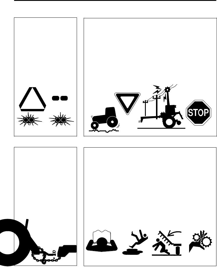
Table of Contents
Important Safety Information
Land Pride
These are common practices that may or may not be applicable to the products described in this manual.
Use Safety
Lights and Devices
▲Slow moving tractors, selfpropelled equipment, and towed implements can create a hazard when driven on public roads. They are difficult to see, especially at night.
▲Flashing warning lights and turn signals are recommended whenever driving on public roads. Use lights and devices provided with implement.
Transport
Machinery Safely
▲Comply with state and local laws.
▲Maximum transport speed for implement is 20 mph. DO NOT EXCEED. Never travel at a speed which does not allow adequate control of steering and stopping. Some rough terrain require a slower speed.
▲Sudden braking can cause a towed load to swerve and upset. Reduce speed if towed load is not equipped with brakes.
▲Use the following maximum speed - tow load weight ratios as a guideline:
20 mph when weight is less than or equal to the weight of tractor.
10 mph when weight is double the weight of tractor.
▲IMPORTANT: Do not tow a load that is more than double the weight of tractor.
Use A Safety Chain
▲A safety chain will help control drawn machinery should it separate from the tractor drawbar.
▲Use a chain with the strength rating equal to or greater than the gross weight of the towed machinery.
▲Attach the chain to the tractor drawbar support or other specified anchor location. Allow only enough slack in the chain to permit turning.
▲Do not use safety chain for towing.
Practice Safe Maintenance
▲Understand procedure before doing work. Use proper tools and equipment, refer to Operator’s Manual for additional information.
▲Work in a clean dry area.
▲Lower the implement to the ground, put tractor in park, turn off engine, and remove key before performing maintenance.
▲Allow implement to cool completely.
▲Do not grease or oil implement while it is in operation.
▲Inspect all parts. Make sure parts are in good condition & installed properly.
▲Remove buildup of grease, oil or debris.
▲Remove all tools and unused parts from implement before operation.
|
|
|
|
|
|
|
|
|
|
|
|
|
|
|
|
|
|
|
|
|
|
|
|
|
|
|
|
|
|
|
|
|
|
|
|
|
|
|
|
|
|
|
|
|
|
|
|
|
|
|
|
|
|
|
|
|
|
|
|
|
|
|
|
|
|
|
|
|
|
|
|
|
|
|
|
|
|
|
|
|
|
|
|
|
2 |
RCR1860 and RCR1872 Series Rotary Cutters 312-849M |
12/17/07 |
||||||||||||||

Land Pride
Important Safety Information
Table of Contents
These are common practices that may or may not be applicable to the products described in this manual.
Prepare for Emergencies
▲Be prepared if a fire starts.
▲Keep a first aid kit and fire extinguisher handy.
▲Keep emergency numbers for doctor, ambulance, hospital and fire department near phone.
911
Wear
Protective Equipment
▲Protective clothing and equipment should be worn.
▲Wear clothing and equipment appropriate for the job. Avoid loose fitting clothing.
▲Prolonged exposure to loud noise can cause hearing impairment or hearing loss. Wear suitable hearing protection such as earmuffs or earplugs.
▲Operating equipment safely requires the full attention of the operator. Avoid wearing radio headphones while operating machinery.
Avoid High
Pressure Fluids Hazard
▲Escaping fluid under pressure can penetrate the skin causing serious injury.
▲Avoid the hazard by relieving pressure before disconnecting hydraulic lines.
▲Use a piece of paper or cardboard, NOT BODY PARTS, to check for suspected leaks.
▲Wear protective gloves and safety glasses or goggles when working with hydraulic systems.
▲If an accident occurs, see a doctor immediately. Any fluid injected into the skin must be treated within a few hours or gangrene may result.
Keep Riders
Off Machinery
▲Riders obstruct the operator’s view they could be struck by foreign objects or thrown from the machine.
▲Never allow children to operate equipment.
12/17/07 |
RCR1860 and RCR1872 Series Rotary Cutters 312-849M |
3 |
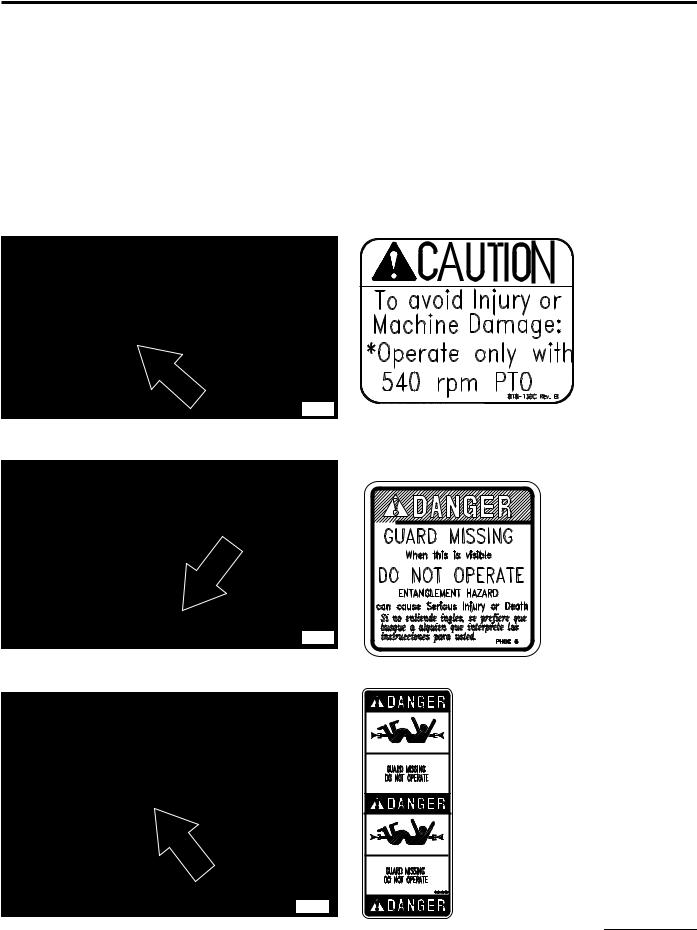
Table of Contents
Important Safety Information
Land Pride
Safety Labels
Your Rotary Cutter comes equipped with all safety labels in place. They were designed to help you safely operate your implement.
1.Read and follow label directions.
2.Keep all safety labels clean and legible.
3.Replace all damaged or missing labels.
4.Some new equipment installed during repair require safety labels to be affixed to the replaced component as specified by Land Pride. When ordering new components make sure the correct safety labels are included in the request. To order new labels go to your Land Pride dealer.
5.Refer to this section for proper label placement. To install new labels:
a.Clean the area the label is to be placed.
b.Spray soapy water on the surface where the label is to be placed.
c.Peel backing from label. Press firmly on surface
d.Squeeze out air bubbles with the edge of a credit card or with a similar type straight edge.
21428 |
21428 |
818-130C
Caution 540 RPM
818-543C
Danger PTO
|
|
21428 |
4 |
RCR1860 and RCR1872 Series Rotary Cutters |
312-849M |
818-540C
Danger Guard Missing
12/17/07
Land Pride |
Table of Contents |
Important Safety Information
ROTATING DRIVELINE
KEEP AWAY!
818-552C
Danger PTO Driveline


 21428
21428
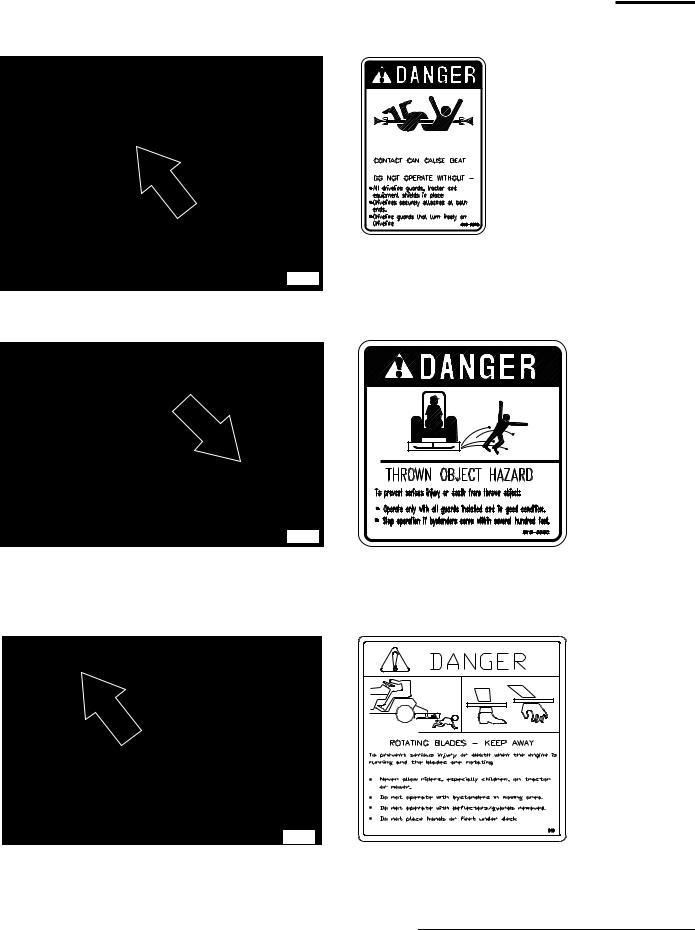
818-556C
Danger Thrown Object
21428
|
818-564C |
|
|
Danger Rotating Blades |
|
|
21428 |
|
12/17/07 |
RCR1860 and RCR1872 Series Rotary Cutters 312-849M |
5 |
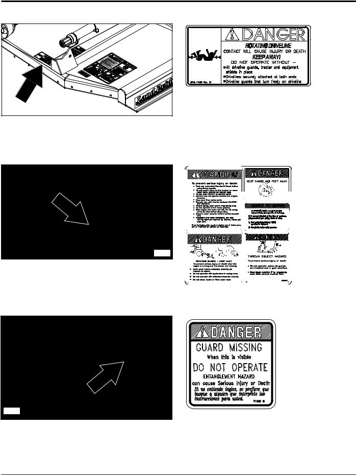
Table of Contents
Important Safety Information
Land Pride
21428 |
818-142C
Danger Driveline

 21428
21428
21418 |
818-830C
Safety Combo
818-543C
Danger Guard Missing
6 |
RCR1860 and RCR1872 Series Rotary Cutters 312-849M |
12/17/07 |

Land Pride
Introduction
Table of Contents
Land Pride welcomes you to the growing family of new product owners.
This Rotary Cutter has been designed with care and built by skilled workers using quality materials. Proper assembly, maintenance, and safe operating practices will help you get years of satisfactory use from the Rotary Cutter.
NOTE: A special point of information that the operator must be aware of before continuing.
Owner Assistance
The Warranty Registration card should be filled out by the dealer at the time of purchase. This information is necessary to provide you with quality customer service.
Application |
The RCR18 Series Rotary Cutter has been specially |
||
Land Pride’s RCR18 Series Rotary Cutters are built and |
designed with genuine Land Pride parts. Contact a Land |
||
designed by Land Pride for cutting on gentle slopes or |
Pride dealer if any repair parts are required or when in |
||
slightly contoured right-of-ways, pastures, around the |
need of customer service. Our Land Pride dealers have |
||
farm or around town. The cutting widths, 60” for |
trained personnel, repair parts and equipment needed to |
||
RCR1860 and 72” for RCR1872, are compatible with the |
service the implement. |
||
more maneuverable 20 to 50 horsepower tractors with |
Serial Number Plate |
||
540 rpm PTO speed. The cutters have a category I three- |
|||
For prompt service always use the serial number and |
|||
point hitch and are Quick Hitch adaptable. They are |
|||
offered with a standard ASAE Category 3 driveline with |
model number when ordering parts from your Land Pride |
||
either shear bolt or slip-clutch protection. Also, they are |
dealer. Be sure to include your serial and model numbers |
||
offered with either a laminated or a solid rubber tailwheel. |
in correspondence also. Refer to Figure 1 for the location |
||
RCR18 Series Cutters cut through grass, weeds, and |
of your serial number plate. |
||
|
|
||
light brush up to1 in. diameter. The RCR 1860 has a |
|
|
|
cutting height range of 1-1/ 2” to 13” and the RCR1872 |
|
|
|
has a cutting height range of 1-1/2” to 11-1/2”. Cutting |
|
|
|
blade tip speed for the RCR1860 is 16,363 fpm and for |
|
|
|
the RCR1872 is 14,955 fpm. These units come with 10 |
|
|
|
ga. (.135” thick) x 24” diameter standard-duty stump |
|
|
|
jumpers and welded on full length skid shoes. A metal |
|
|
|
band shield is standard equipment for the rear. Optional |
|
|
|
shields for the front and rear are rubber deflectors and |
|
|
|
chain guards. See “Section 7: Features & Benefits” for |
|
|
|
additional information. |
|
|
|
Using This Manual |
|
21417 |
|
|
|
||
• This Operator’s Manual is designed to help familiarize |
|
Figure 1 |
|
you with safety, assembly, operation, adjustments, |
Further Assistance |
||
troubleshooting, and maintenance. Read this manual |
|||
Your dealer wants you to be satisfied with your new |
|||
and follow the recommendations to help ensure safe |
|||
and efficient operation. |
Rotary Cutter. If for any reason you do not understand |
||
• The information contained within this manual was |
any part of this manual or are not satisfied with the |
||
service received, the following actions are suggested: |
|||
current at the time of printing. Some parts may change |
|||
1. Discuss the matter with your dealership service |
|||
slightly to assure you of the best performance. |
|||
• To order a new Operator’s or Parts Manual contact |
|
manager making sure he is aware of any problems |
|
your authorized dealer. Manuals can also be |
|
you may have and that he has had the opportunity to |
|
|
assist you. |
||
downloaded, free-of-charge from our website at |
|
||
2. If you are still not satisfied, seek out the owner or |
|||
www.landpride.com or printed from the Land Pride |
|||
Service & Support Center by your dealer. |
|
general manager of the dealership, explain the |
|
Terminology: |
|
problem and request assistance. |
|
3. |
For further assistance write to: |
||
“Right” or “Left” as used in this manual is determined by |
|||
facing the direction the machine will operate while in use |
|
Land Pride Service Department |
|
unless otherwise stated. |
|
||
|
1525 East North Street |
||
Definitions: |
|
||
|
P.O. Box 5060 |
||
IMPORTANT: A special point of information related |
|
Salina, Ks. 67402-5060 |
|
|
|
||
to its preceding topic. Land Pride’s intention is that |
|
E-mail address |
|
this information should be read and noted before |
|
lpservicedept@landpride.com |
|
continuing. |
|
||
|
|
||
12/17/07 |
RCR1860 and RCR1872 Series Rotary Cutters 312-849M |
7 |
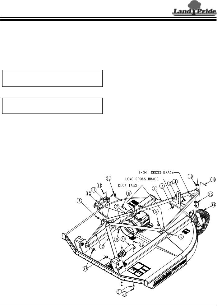
Table of Contents
Section 1: Assembly and Set-Up
Tractor Requirements
The RCR18 Series Rotary Cutters are designed for use with tractors that are equipped with a (540 RPM 1 3/8”-6 spline) rear power take-off (PTO).
The tractor must also provide for 3-point hitch attachment Category I. The tractors rated drawbar PTO horsepower on a 3-point should be no less than 20 HP and no more than 50 HP.
NOTE: Ballast weights may be required to maintain steering control. Refer to your tractor’s operator’s manual to determine proper ballast requirements.
RCR1860 & RCR1872
Refer to Figure 1-1:
1.Loosen 5/8” locknuts (#5 & #13).
2.Remove 5/8” x 5” bolt (#9) and lay aside pivoting upper hitch (#10) and hitch spacer (#11).
3.Rotate A-frame braces (#12) and rear frame braces (#7) up to align with each other as shown. Rear braces (#7) should be located outside of front A-frame braces (#12).
4.Attach pivoting upper hitch (#10) and spacer (#11) to A-frame braces (#12) with 5/8” x 5” bolt (#9). Secure in place with locknut (#8).
Dealer Assembly
NOTE: Do not tighten hardware until assembly is complete. Refer to “Torque Values Chart For Common Bolt Sizes” on page 28.
RCR1872 Tailwheel A-Frame
Refer to Figure 1-1:
1.The RCR1872 tailwheel A-Frame (#1) is shipped with its short cross brace attached to the adjusting bracket (#2). Remove 5/8” locknut (#3) and
5/8” x 1 1/2” bolt (#4).
2.Remove 5/8” locknuts (#5) and 5/8” x 2” bolts (#6) from tailwheel A-frame.
3.Reinsert 5/8” x 2” bolts (#6) through deck tab, rear brace (#7) and tailwheel A-frame (#1). Secure with 5/8” locknuts (#5). Draw nuts up snug. Do not tighten.
4.Reinsert 5/8” x 1 1/2” bolt (#4) and secure with 5/8” locknut (#3). Do not tighten.
5.Draw lock nuts (#5) up snug. Do not tighten. Tighten all other 5/8” locknuts (#3, #8 & #13) to 170 ft.-lbs.
6.Install machine washer (#15) on pivot shaft of tailwheel (#14).
7.Insert tailwheel pivot shaft (#14) into tailwheel A-frame (#1).
8.Install second machine washer (#15) on pivot shaft of tailwheel and secure with roll pin (#16).
9.Attach driveline hook (#17) to pivoting upper hitch (#10) with 3/8” hex nut (#19). Tighten nut to the correct torque.
10.Attach manual storage tube (#22) to the cutter deck with two 1/4”-20 x GR5 hex head cap screws (#18). 1/4” lock washers (#21) and hex head nuts (#20).
Tighten nuts to the correct torque.
21407
Figure 1-1
8 |
RCR1860 and RCR1872 Series Rotary Cutters 312-849M |
12/17/07 |
Loading...